Find us on Google+ Inventor Tales

Wednesday, July 21, 2010

Lost Inventor Tool Ribbon. Answers the the Name "Vault"

“Buying the right computer and getting it to work properly is no more complicated than building a nuclear reactor from wristwatch parts in a darkened room using only your teeth.”  
Dave Barry


Every once in a while, you see a strange little thing come up.  You don't know why, but it's easy to fix once you know where to look.


In this case, a Vault ribbon doesn't show up, even though the Vault client was installed.  


It was puzzling, but the fix ended up being pretty simple.  In the end, it turned out that the add-in for Vault wasn't starting when Inventor was started.  Clicking a few buttons was all that was needed.


The first step was to go to the Tools ribbon, and Choose Add-Ins.  

Choose the Tools Ribbon, and click Add-Ins

After choosing the Add-Ins icon, you'll see the add in screen.  Once this comes up, select Inventor Vault and make sure that the Loaded/Unloaded and Load on Startup options are both checked for that line item.

Make sure the indicated options are checked for Inventor Vault

Once you do this, The Vault Add-In will start, and the next time you start Inventor, the Vault ribbon will be available.


The Vault ribbon found
Granted, this won't fix every issue, but when Vault is installed, and you can't get it to show up in Inventor, many times, this will fix it!

Happy Inventing!

Saturday, July 17, 2010

Life Lessons - The Ghost of Engineers Past

“There is a certain majesty in simplicity which is far above all the quaintness of wit.” 
 Alexander Pope 

We live in a world where things we take for granted would have been considered science fiction only fifty years ago.

Today I've updated my Facebook and Twitter pages from my Blackberry Storm (on which I've also received several e-mails today). I also used a GPS to find the coffee house where I'm writing this blog with a laptop that has more calculating power than the computers that flew to the moon and back.

In a world of ever increasing complexity, I know I often forget the beauty and elegance of a simple solution.

Today I was walking the floors of the Planes of Fame air museum (where I saw a great seminar on aerial photography by Paul Bowen), and notice some ingenious solutions created by our engineering forebears.

The first, if you're flying a 1940s vintage aircraft, and need to check to see if you're landing gear had lowered, what did they do? Gauges, sure! They had them.

But what if you wanted to double check?

The designers created a simple tab on top of the wing that popped up when the landing gear was down. Purely mechanical, just a little piece of metal.

The landing gear indicator on a A6M5 Zeke "Zero" Japanese fighter
Yes this is a real, flyable WWII era Japanese Fighter
The indicator is just highlighted, on top of the wing, above the landing gear
(click to enlarge)

A closer look at this simple solution


The same solution on a Russian Yak-3
(click to enlarge)

Another incredibly simple solution, the 'yaw' indicator on the N9MB Flying wing.
'
Considered the B-2 Spirit's 'grandfather', this aircraft tested the flying wing concept back in WWII.

I'm told the airplane has a tendency to yaw (if your looking from the top, the nose would be swinging from side to side slightly). It is however equipped with a yaw indicator.

How does this sophisticated instrument work? It's a piece of string attached to the nose in front of the pilot. If the string is blowing to the right or left, the airplane is yawing. If the string is blowing back toward the pilot, the airplane is flying straight.

That's right, the precursor to one of the most sophisticated aircraft in the world today used a piece of string as a flight instrument.

The flying wing back in May
(click to enlarge)


The back of the Flying Wing
(click to enlarge)


Notice the string between the canopy and the Northrop decals
This is the yaw indicator
(click to enlarge)

So why do I mention this? Because I think we all get caught up in complex solutions involving computer controlled whirlygigs with a galloping rod adjusting feedback loop, that sometimes, we forget that there might be a simpler solution for that.

If anything, seeing things like that makes me appreciate (and look) for the lessons taught by the designers who sat at a drafting board where the sketching toolbar was a pencil, the delete key was an eraser, and the 'computer' was a slide rule.


Tuesday, July 13, 2010

Chains of Thought - Chain Dimensions in Inventor


“Loyalty to petrified opinion never yet broke a chain or freed a human soul.”

Mark Twain


Chain dimensions in a manufacturing drawing have always made me 'squidgy' (that's the official term for it).

When you start thinking of how chain dimensions can affect tolerances, and how they stack up across a set of chain dimensions, it can get a little bit frightening.

Chain Dimensions
(click to enlarge)

In the sample above, look at how the tolerances stack up, let's assume a dimension of +/- .005

That means that the '3.916' dimension can vary safely between 3.911 and 3.921. So far, so good.

But we start to see a problem with the next dimension, 10.284. The way this is dimension is placed, it's .005 tolerance adds up with the previous dimension, meaning that it can actually vary between 10.274 and 10.294, and still meet the tolerances as dimensioned (even if that's not what's intended.

As we go on, the 7.50 dimension will stack up with the previous two, and so on. The problem compounding as the chain passes the previous tolerances to the next.

This is why baseline dimensions are so popular among the mechanical crowd.


Baseline dimensions. Nice, safe, baseline dimensions.
(click to enlarge)

In this case, the dimensions are all measured from the edge, and totally independent of each other. This eliminates the 'stacking' issue that chain dimensioning has with tolerances, and generally conveys that this part needs to be held to a tighter tolerance.

But does that mean that as a manufacturer, you'll NEVER use chain dimensions?

Not necessarily. The obvious case for chain dimensions is when tolerances aren't important, such as a rough cut, or a series of outside dimensions with loose tolerances.

The other is a case where the dimension from edge isn't as critical as another dimension. Looking at the example below:

I have a stretcher, a common tool in woodworking. There are many cases where the length of the shoulder is critical, and the tolerance of the tabs (known as tenons), is secondary to that shoulder length.

Cases such as this, and also cases similar to this are where I've used chain dimensions to get exactly what I want.


Chain dimensions used to get the desired effect.
(click to enlarge)

A dieset using chain dimensions. The Center to Center between the pins is critical.
The sides are flame cut a typically only for reference
(click to enlarge)

So there, you can see where chain dimensions aren't ALL bad. Like most tools, it's knowing when you can make the best use of them.

Food for thought I hope!

Sunday, July 11, 2010

Taking a Sampling - Where Did My Inventor Sample Files Go?


“The proof of the pudding is in the eating. By a small sample we may judge of the whole piece.”

Miguel de Cervantes Saavedra


Last week I was fortunate enough to receive my new laptop. 64bit Windows 7, 8 GB of RAM, 500GB hard drive. It'll be a dream for at least the next 6 months, before the next dream box comes along.

Of course with that comes the installation of the software I'm using. To date, I have Inventor, Vault, and Showcase installed. Not to mention Snagit, Camtasia, and several other small programs I usse

After getting my system ready I found that I need to run a quick test on some files. No problem! I'll just grab a sample file! There's sheet metal parts, assemblies, drawings, a slew of flies I can use for a quick test when I don't have the time or desire to build a data set.

Well, when I went to get them, they weren't there! There were some iLogic files, a translator folder, and an html document named 'Where are my sample files'.


The 'Where'd they go file'
(click to enlarge)

Not to fear, if you click on the html file, it opens up to a hyperlink that takes you to a page where you can download the files.

Found them!
(click to enlarge)


The link will take you to the download page but if you're reading this blog, you can just go ahead and follow the link here.

It definitely saves the disappointment of finding the location (which can vary if you're on Windows XP versus Windows Vista/7).

If you're a CAD Manager or IT in charge of getting the files, you can also download them and put them on a server instead of hunting for them when you're asked. Then you get kudos for being proactive!


The download page
(click to enlarge)

That's it for this weekend, just a small tip today, but don't worry. I'm thinking of what to do next already!

Monday, July 05, 2010

A Stroll Down Memory Lane - Level of Detail


The memory of things gone is important to a jazz musician.
Louis Armstrong


It's been a long time since I visited this (the tool originally came out in Inventor R11), and I've never done it in a video format, and that's the use of Level of Detail (aka Load on Demand) inside of Inventor.

Level of Detail inside Inventor
(click to enlarge)

We'd all dream of a monster machine with enough RAM to make a minor deity jealous, but we can't always get it. For example, if you're still running a 32 bit system, you're stuck with 4GB of RAM. You can't go any higher.

So when faced with this, Level of Detail can make a huge difference when your system starts hitting the wall.

So what exactly is Level of Detail, or LOD?

LOD allows you to unload unneeded components in an assembly from memory, freeing up RAM to work on the components you do need. It can be used to unload components after you open your assembly, and it can also be saved, and recalled when you open your assembly, allowing fora faster load time.

So without further adieu, here's the video!


So that's Level of Detail in a nutshell.

A few updates from my Plane's of Fame volunteer gig. This weekend the TBM Avenger flew. Unfortunatley, I forgot my good camera, so no aerial shots of the Avenger flying. But I did get a slick picture (at least I think so) of the WWII reenactors posing in front of it.

Open it up in Techsmith's Snagit, change the picture to monochrome and add an edge effect, and it almost looks like it could be from the 1940s! Granted, if you look carefully, you can bust it as being modern. But hey, I'm only an amateur!


The TBM Avenger
(click to enlarge)

Happy Inventing!

Tuesday, June 29, 2010

I Don't Remember Having a Memory Problem! - The Inventor Memprobe Utility


“We cannot change our memories, but we can change their meaning and the power they have over us”

David Seamands


I'm a huge convert to the 64 Bit Windows 7 operating system. I've switched over, and never once looked over my shoulder to XP or Vista. I know there are those who will disagree with me, but personally, the Windows 7 transition has been the happiest transition I've ever made from one OS to another.

With respect to Inventor 2010 and 2011, I've been pleased with the performance. Time to tear off the proverbial review mirror, and not even look over my shoulder.

But I did have to give up my memory meter in the lower right had side of the screen. It doesn't show in 64 Bit systems. It was definitely a 'Nice to Have', although I wouldn't go back to a 32 bit OS to get the meter back.

However, there is one place you can still get a memory meter of a sort on your system. Thanks to Nicole Morris for showing me this trick. I'm afraid I can't take the credit for this one!

If you browse to the 'Bin' directorry in your installation directory, typically: C:\Program Files\Autodesk\Inventor 2011\Bin

This will bring up a memory monitor called Memprob that you can also use to keep track of your memory.


Memprobe running
(click to enlarge)


You can also use the pulldown to control the settings you want to record, to create log files, and so on.

Setting which processes to monitor
(click to enlarge)

Setting refresh speed, log files, etc.
(click to enlarge)

Control how you want to view Memprobe while it's running
(click to enlarge)

So here you are, a different way to skin the cat, it's definitely something I'll be using in the future!

Sunday, June 27, 2010

Getting Previous Versions from Autodesk Vault & the Shifting Sands of Workflow

A sudden bold and unexpected question doth many times surprise a man and lay him open.
Francis Bacon


If you've heard about Autodesk Vault, you've almost certainly heard that it will allow you to retrieve previous versions of a file. This is a definite advantage to having something like Vault, especially when you need to create several design iterations, or just need to recover from a mistake.

The blessed getting of the Previous Version
(click to enlarge)

Personally, I haven't used this feature in practice for a while, and it's not because I don't make mistakes, it's just because I haven't had a chance to get back in there and chew on Vault.

So last week I had to run a quick Vault update course. Nothing flashy, the basics.

So I made sure to be diligent. I ran through my exercises and made sure nothing changed in the workflow.

Everything is as I remember it. I'm ready to go to town!

But then, at the last moment, at the very last step, I can't get the older version to update and become the current versions. This is the last step in the retrieval, what's going on?!? Vault is forcing me to update the file, and bring back the version I'm trying to replace.

I actually appreciate what Vault is trying to do, prevent me from opening an old version, but NOT NOW! I WANT THE PREVIOUS VERSION!

I pour over things, I Google it. I scratch my head. Something has changed, or I'm losing my mind!

Finally, after a few trials and errors, plus a couple of Google searches, I realize theres been a slight workflow change. Nothing major, but enough to drive me nuts.

Lesson 1: Watch out for workflow changes.

Lesson 2: Don't assume ANYTHING!

Wednesday, June 23, 2010

What's Old is New Again. Sketch Blocks in Inventor.


“The wireless telegraph is not difficult to understand. The ordinary telegraph is like a very long cat. You pull the tail in New York, and it meows in Los Angeles. The wireless is the same, only without the cat.”

Albert Einstein


I too am sometimes guilty of not trying something new because the old way works 'just well enough to not change'.

A tool that fell into this category is sketch blocks in Inventor's sketching environments.


An example of sketch blocks in Inventor laying out the suspension
(click to enlarge)

I saw it once in a demo, and thought "Hey, that's cool! I should remember to take a closer look at.... LOOK A SHINY THING!"

Needless to say, it wasn't until just this week I had, what in marketing speak is referred to as a "Compelling Event' to revisit this.

Now that I have that compelling event, I can look back and think of my college senior project, the SAE Mini-Baja. We build a small off-road car for a competition way back when, in 1996.

Rolling something out of the 'if I knew then what I knew now' category, here's a video on how we might have done things differently, had we had Inventor then.


If only we'd had it then. I think we would have been done a lot quicker. But sometimes all we can do is wish.

Happy Inventing!

Monday, June 14, 2010

The Bill of Materials. Turn Your Hindsight into Foresight


Any problem can be solved using the materials in the room.
Edwin Land


First, a disclaimer. I was working on a customer site, so the files I'm using my own files to reproduce the challenge. It wouldn't do for me to use their files without their permission.

Think of this as the letters that say 'dramatization' at the bottom of those documentaries you see.

Today, was working on a drawing and we ran into a situation that is very common in the design world.

Change.

It turned out that the part we were using had the wrong number assigned to it, and it had to be changed to the correct number.


One wrong part number can ruin the recipe
(Click to Enlarge)

Normally, this is an easy operation, but the part was used in several drawings, and called out in the Bill of Materials for each one.

In the old days, that meant that going to each drawing and changing the part number was going to be tedious, and error prone.

Fortunately, there is a better way to do this.

Each assembly file has Bill of Materials information that can be edited. Best of all, this information gets published to both the part, and to all the drawings using that part.

First we access the Bill of Materials button in the assembly.


The Bill of Assembly button
(click to enlarge)

Now we see the Parts List info, including our suspect part.

Here's the field in the assembly Bill of Materials
(click to enlarge)

A couple of edits, and we have our corrected number

The number corrected. Now we're getting somewhere!
(click to enlarge)

Even better, the information can be saved back to the part, so when you use the part in the future, the correct information will go into the parts list.


(click to enlarge)

I've really grown to like this tool!

On a final note, while I used the part number in this example, you can change a number of fields. You can choose them via the Column Chooser.

The Column Chooser
(click to enlarge)

Happy Inventing!

Thursday, June 10, 2010

Hide, Seek, and Find in Autodesk Vault.


“The voyage of discovery is not in seeking new landscapes but in having new eyes.”

Marcel Proust


Unfortunately, I'm not going to put up the Inventor Fusion video I promised, partially due to my dog sitting commitment for my sister and brother in law this week, which caused me to leave my headset at home.

Meet Smokey, one of the little dogs I'm watching.
He does a mean job of holding the couch down.


Also, the schedule has indeed proved busy enough where I wouldn't have had the time to sit down.

But there is something to talk about.

This week I've been working daily inside of Autodesk Vault, hours on end, searching, finding, checking in, and checking out.

I've learned one thing about Vault that I've always thought was a great idea, but after using it for nearly a week straight, I've come to love it.

The Find button.

Autodesk Vault runs on a database, so when you're searching for files, you scan the database instead of a file search like we might do in a conventional folder system. Scanning the database is much quicker.

I like to think about it as going to the library and looking up a books location in the computer (the database), opposed to walking up and down the isles looking for the right book (the folder structure).

Assuming you're using Vault, an easy way to search the database is to choose the 'Open from Vault' button from the Vault Ribbon

Open from Vault
(click to enlarge)

Once you click on the icon, the 'Open from Vault' dialog box opens up. Hit the find button, and you're ready to scan the database for those files, just like standing in front of that computer in the library.


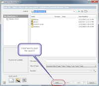
Choose 'Find' to Start Searching
(click to enlarge)

Now I can enter the data I want to search on. One of the strengths of this tool is that several properties, such as part numbers, comments, and other data are search-able. You're not just limited to filename.

Get ready to search!
(click to enlarge)

I've entered the word 'Green', knowing that's something I want to search for. Then I tell Vault to start finding. I'll end up with all the files that meet that criteria.


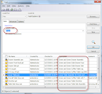
All the files that are found in the search
(click to enlarge)

Now you can select a file, and hit OK. Vault plugs the file you choose into the Open Dialog box, and now you're off and running.
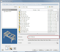
Ready to Go!
(click to enlarge)

The last week that I've been using Vault constantly, this find tool has become my best friend.

All I needed was a part number, and I could start rolling. I didn't need to know the folder structure, and I could search files a lot more quickly when we weren't sure which of several files was the one we were looking for.

It's definitely a tool that I've come to like.

Sunday, June 06, 2010

The Sum of Their Parts, Inventor and Inventor Fusion

We have such a mixture now, such a fusion of different genres.
Ryszard Kapuscinski

One of the new Features that''s often mentioned in Inventor 2011 is the ability to use Inventor Fusion to edit base (often referred to as 'dumb') solids for Inventor.

It's great that we know it can be done, but how about how it can be done!

First, you need to get Fusion. If you opted to recieve the DVDs in the mail, it'll be one of the DVDs in the box. (If you don't know how to request your media, there's a KETIV tech tip HERE.)

It's also available from the Autodesk Labs website HERE.

Finally, it's also available on the subscription website if you opted to download your 2011 software. Click HERE (login required).

It's not hard if you know where to look. The first step, is to to go to Application Options, and on the Part tab, make sure you set Base Solid Editing to 'Inventor Fusion'.


Choose your settings
(click to enlarge)

That's it. Now when you want to edit a base solid, just right click on the Base Solid, and choose 'Edit Solid'


Editing a Solid in Inventor
(click to enlarge)

Inventor will tell you it's switching to Inventor Fusion for it's solid editing functions.


Fusion Bound!
(click to enlarge)

Now Inventor will close and Inventor Fusion will open, allowing you to edit the part using all of Fusion's capabilities.

Ready to edit in Fusion
(click to enlarge)

When you're done, click the icon to return to Inventor, and the solid will be back into Inventor, ready to go.

Editing done! We're ready to go back to Inventor
(click to enlarge)


The changes now viewed in Inventor
(click to enlarge)

And that's it. Using Inventor Fusion to edit your solids. If you want more info on Fusion, look back to this blog. Schedule permitting (I have to put in that disclaimer), I hope to put some info on that later this week.

But you can also find info on Fusion from Rob Cohee's Youtube Channel! Check it out HERE!

Thats it for now. I have a new assignment to start working on tomorrow, so I want to be rested up!

Happy Inventing!

Monday, May 31, 2010

Breakout Views. Detailing for Clarity.

“The man who has seen the rising moon break out of the clouds at midnight has been present like an archangel at the creation of light and of the world”

Ralph Waldo Emerson


When I was working in industry, I created a lot of cylindrical parts that had internal features. I created more O-Ring grooves than I want to think about!

That translated into having to create a ton of Breakout Views.

Inventor's Breakout Views are pretty easy in my opinion, but that doesn't mean there aren't a couple of places you can get tripped up.

The basic steps are:
  1. Select the view to breakout (don't miss this step!)
  2. Draw a closed profile
  3. Finish the sketch
  4. Choose 'Breakout View'
  5. Select Options
  6. Hit OK.
Everyone (including myself) tends to make a mistake on Step 1. If you don't select the view first. You'll get the following error:


This error isn't as scary as it looks. Just make sure to select the view first.
(click to enlarge)


If you see it, don't panic! Just make sure you pick the view you want to use first!

As always, a picture is worth a thousand words, so here's a video to go with it!


On a non-Inventor note....

For those in the United States, Happy Memorial Day.

At the Planes of Fame Museum I was lucky enough to sit in the top turret of a B-17 Flying Fortress that is currently under restoration.

It was very cool, but also pretty humbling when I considered the courage of the crews that were in there in combat. Thanks to all those who flew those for real, so I could sit in there for fun.


Here I am sitting in the top turret of a B-17 Flying Fortress. I know I look angry, but I'm really just squinting because of the sun.


The 'business end' of the B-17s top turret. The .50 caliber machine guns are non-functioning of course. That's a DC-3 in view of the turret.


Tuesday, May 25, 2010

Repeat Last Command. Sometimes it's About the Little Things.


“Enjoy the little things, for one day you may look back and realize they were the big things.”

Robert Brault quotes


As I was getting ready to train a class tomorrow, I came to realize a nice little trick that I've come to use all time time, and since it's introduction (in Inventor 2010, as I recall), I've come to take it for granted.

What is it?

Right click to repeat your last command.

The AutoCAD gurus know this one well. They've used it for years. Now, those of us on the Inventor side can make use of it!

The right click 'repeat command' option. In this case, allowing us to repeat 'Place Component'
(click to enlarge)

The option appears at the top of nearly every right click menu, allowing you to quickly reuse the previous command without having to go to a ribbon.

This is a great tool. I've taken to using it hand in hand with tools like the new Assemble tool.

It's easy to miss, but well worth giving a try to.

Oh, and if you're really an AutoCAD guru... You can hit the space bar to reactivate the last command too!

Sunday, May 23, 2010

Using the Assemble Tool to Put it All Together


It was exactly an assembly line. You could look into infinity down these rows of drawing tables.
Gil Kane


One of the new Inventor features that I've come to like the more and more I use it is the new Assemble tool.

The Assemble Tool in Action
(click to enlarge)

This tool let's you apply assembly constraints just by picking the correct geometry, and 'fine tuning' a bit with your direct manipulation tools. You don't have to activate the Constraint tool and tell Inventor which constraint you want.

I had to take some time to practice to get the nuances of it but now that I'm getting those down, all I can say is; 'Wow, I'm having fun now!'

Here's a video I put together. Notice how I use the 'Select Other' tool to cycle through different assembly constraint options.


Happy Inventing!

Monday, May 17, 2010

Finding Hidden Treasure - Degree of Freedom Analysis in Inventor

“Should not every apartment in which man dwells be lofty enough to create some obscurity overhead, where flickering shadows may play at evening about the rafters?”

Henry David Thoreau


While working with an assembly, I stumbled upon a tool that, in the 'fog of time' I'd quite frankly, forgotten about.

Degree of Freedom Analysis.

This slick little tool will show you a dialog box with the remaining translational and rotational degrees of freedom on the parts in an assembly, as well as letting you animate them.

After taking a few minutes to reacquaint myself with this little gem, I don't think I'll be forgetting about this one anytime soon.

The tool is located in the Assembly file in the Productivity section of the Assembly toolbar.


Finding the hidden treasure - Degree of Freedom Analysis
(click to enlarge)

Choosing this tool, you'll see a dialog box showing how many degrees of freedom remain for each component in the assembly. The columns will be split up into translational and rotational.

The degrees of freedom for this clamp
(click to enlarge)

Each component shows the number of rotational and translational degrees of freedom left for each component. If you select a component in the browser, the degrees of freedom will highlight on the corresponding part on the assembly model.

Selecting a component in the dialog box will display the Degree of Freedom indicator for that compononet
(click to enlarge)

One final note, checking the Animate Freedom check box will also animate the component, moving it any degrees of freedom that remain. This can make it a lot easier to find the degrees of freedom that remain, and which ones you may still need to remove to properly constrain the component.


A snapshot of the animation in action
(click to enlarge)

So there it is! A nice little gem that can really help find where new constraints need to be added.

I know now that Ive rediscovered that tool, I'll not soon forget it again!