Find us on Google+ Inventor Tales

Sunday, June 17, 2012

Using an iLogic Form to Make a Rule User Friendly in Autodesk Inventor

“Everything that is simple is theoratically false, everything that is complicated is pragmatically useless.”
 Marleen Paul Valery

In last week's blog.  I created an iLogic rule that changed the length, width, and thickness of a board for the template I use in my woodworking projects.  It also turned the tenon joint on and off, as well as setting the dimensions of the tenon.

But, while effective, the rule could be refined to make it more effective.  This is especially true when looked at with respect to ease of use.

So in this blog post, we don't make the rule.  We make the rule better.

How do we do that?  We create a dialog box, or form, that makes the rule easier to interact with.  It puts all the critical inputs in one simple, easy to use interface.

The board with the form open.

To create the form, right click in the iLogic Browser, and choose "Add Form"

Adding the new form
Next, drag and drop the desired parameters from left to right to create the form.  That's it!

Drag from left to tight to build the form.
Labels of Parameters can also be changed, so you can make them look exactly the way you want them to.

We'll also set up two types of triggers.  This will help control when the form is displayed.

The first, is an Event Trigger that will start the form when the template starts. 

The second, will fire the form when the iLogic "iTrigger" icon is clicked. This will let us fire the rule, "at will".

In order to create the iTrigger functionality, add a new rule by clicking "Add Rule" from the iLogic Panel on the Manage tab.

The :"Add Rule" icon
Give the rule a name, and type the following code.

'Fires rule when "iTrigger" icon is clicked
trigger = iTrigger0
'Shows form named "Board Options"
iLogicForm.Show("Board Options")

Where "Board Options" is the name of the form created.

Now this rule will fire when the 'iTrigger" icon is clicked.


Next, we add an "Event Trigger" which fires the rule when the template starts.

Selecting the Event Trigger
Setting the rule to fire when the template starts.
Now of course, this blog post wouldn't be complete without a video!  So here it is!


Have more ideas?  Leave a comment!

P.S. If you'd like to download the part used for this blog post. It's located on the GrabCAD website here!

Tuesday, June 12, 2012

Turning Features On & Off - An iLogic Enabled Template in Autodesk Inventor

“You can't keep putting bodies against it. It's becoming too quick and complex. You have to automate the process and have standard policies.”
Andrew Bird

One of the side projects I work on semi-regularly is designing furniture in Autodesk Inventor.  Mostly, that means taking designs that I find on the web or in books, and increasing the detail to the point of having full piece and assembly drawings.

I quickly learned to create templates containing "board blanks".  Templates that contained a board already created, with parameters named "Length", "Width", and "Thickness".

The original template.  Just a board with Named Parameters


Instead of redrawing that geometry every time, I would start a template with the geometry already created, and I was off to the races!

But soon, I found that I was using a lot of tenon joints.  So I went ahead and created a second template with a tenon joint in it.


The tenon "enabled" template.  With it's extra parameters

And I was proud of my ingenuity.

But now the challenge I faced was caused by my poor memory.  There were many times I grabbed one of the templates, then part way through realized I should have grabbed the other template!

So I simplified my templates to one template that contained all I needed.

 I created a template where I could control the suppression of the tenon using an iLogic Multi-Value List.  Now I had something I could toggle on and off at will.  With the flip of a switch, a "standard" board, or a "tenon" board.

The combined template.  The Multi-Value List shown with it's two options

And I was *very* proud of my ingenuity!

But now, to "add octane to the mix" as said by Paul Munford in his blog post on "The CAD Setter Out"

Over time, here and there, I created a better interface.

Over the years, and releases of Inventor, utilizing spurts of motivation to overcome barren planes of procrastination,  I added a dialog box.  Now I had something that was easier to interact with then opening parameters

A few months later, I got around to setting the dialog box greet you on file creation, saving the trouble of activating manually.

After completing that task only a few weeks ago, I decided to share this template with the world, so to speak.  

This is one of those blog posts that frankly, I procrastinated on a bit.  Why?  It's a lot to write up.

So to ease the task I'm breaking it up into parts.  So, first, let's get something functional.

How to Suppress and Unsuppress the Tenon!

For starters, name your parameters.  It makes them easier to work with when creating your code.

 Note the bottommost parameter "Joint Type" this is a multi-list that sets what type of joint is used.

Also, note there are a "Shoulder_Length" and an "Overall_Length" parameter.  This parameters are toggled depending on whether or not a tenon is placed on the part.  Ultimately, this parameter can be exported to the parts list for a cut length.


The Parameter list. 

Once those parameters are created.  Create an iLogic rule and use the following code to drive the rule.

'If Parameter "Joint_Type" is "Tenon Joint", then unsuppress the feature named "Tenon"
If Joint_Type = "Tenon Joint" Then
Feature.IsActive("Tenon") = True
'Set Value of Length equal to Parameter "LengthOL" (for eventual parts list export)
Length = LengthOL

'If Parameter "Joint_Type" is "Regular Joint", then suppress Feature named "Tenon"
ElseIf Joint_Type = "Regular Joint" Then
Feature.IsActive("Tenon") = False
'Set Value of Length equal to Parameter "Shoulder_Length"(for eventual parts list export)
Length = Shoulder_Length
End If

Check out the video below for the fulls steps.


In Conclusion

This portion of the blog only gets to that "functional" part of the rule  It works great, but it requires that the parameter screen be opened every time.  It may not be elegant, but it is effective.

I ran it like this for quite sometime?  Why?  It worked, and I never got around to further tweaking.

It's that classic case where I fell victim to "good enough".

In the next post, we'll add a form and make this rule run more efficiently and more user friendly.

Monday, June 11, 2012

Postponing this Weeks Blog a Bit

“Vacation is what you take when you can't take what you've been taking any longer.”
Anonymous

This weekend I had a nice getaway with friends in Big Bear, Ca where we attended the Victorian Days Faire.

As always, fun was had by all, but there was no blogging to be done.

Look for a blog later this week!  I've got some things in mind, I just have to sit down and build up the video.

Until then here's a few pictures from the Faire

Old buildings on the Faire Grounds

Gallows Humor.  One of the entertaining bands.

Sunday, June 03, 2012

Simplfy... Simplify Me - Inventor Simplfication from Autodesk Labs


In my post last week, I talked about how you could remove features and voids using some of the new tools in Autodesk Inventor 2013


Now, while cruising about the internet, I find Inventor Simplification. Brought to us by the team at Autodesk Labs


Admittedly, this tool did come out back in April, but I only got to install and start driving it late last week.  


So what about it is so wonderful that it warrants a blog post? 

I was impressed by the workflow.  There are only four tools, all located on a "Simplfy" tab that's added to Inventor's ribbon.


y
Just for buttons!  That's it.


  Another plus, is the flow is pretty natural, at least in my humble opinion.  The basic steps are:

  • Select the components to be added to the simplification by picking, or using a filter for external parts

    • Inventor Simplify creates a View representation containing the parts selected

  • Export the parts to an Inventor part file that now contains the simplified geometry.  If desired, the exported geometry can be edited further by patching holes.  This removes additional detail, or even voids.

Optionally,  components can be reduced into "envelopes".  In other words, show the volume the components occupy, without showing the actual component.  Handy for removing that intellectual property you don't want to show!


Additionally, if components need to be removed from the simplification, the View Representation can be edited. This makes it a lot easier to make adjustments.


An example of a simplified component

As always, I've got a video where you can take a look at the process.  If, after seeing the video, you can't wait to get your hands on it, you can download it at the link here


Have thoughts or cool uses for Inventor Simplfication?  Throw out a comment.


On a more personal note.  I've tried removing the "bookend" slides from the video.  I'm looking for a little feed back on if the users out there would like them better "out" or "in".  Let me know! 

Monday, May 28, 2012

Removing Features and Voids Using Autodesk Inventor 2013's Derived Component Tool

About that time, stronger features became fashionable on the screen.
Marie Windsor

Many of us have been there before.  We need to send our 3D CAD assembly to a 3rd party, like a vendor, for example.  But we don't want to directly export the full 3D model.

Why?  The 3D model contains all the information required to build the components within the assembly.  The "feature rich" assembly may be overkill because the extra information, such as internal cavities, may create a model that is "overly heavy and complicated" for the end user.

Even worse, giving them that feature rich model may give away proprietary information that may allow an unscrupulus end user to take advantage of our hard work.

Would you always want to send out a model with all this detail to a 3rd party>?


In older versions of Autodesk Inventor, you could derive the assembly into a part model, and use standard Inventor part modeling tools to remove the excess features.  You could even use Autodesk Inventor Fusion if you wanted.

But this process took time, and while it might be worth it to protect intellectual property, who doesn't want a faster way.

As of Autodesk Inventor 2013, there is a way.

To take advantage of this new tool, the model is still derived into a part file using the Derived Component too, just like before.

We still go into Derived Component


We can still go into the Options tab, and change how the assembly is derived and remove parts and features that we don't need.

But now check out the "Options" tab for the new options.

But a new option in this window is to remove internal voids that allow the part to be quickly simplified.  With the addition of this tool, manually filling holes, voids, and generally "dumbing down" an assembly can be reduced, or even eliminated.

Remove voids!  The new tool! 

So on that note, here's a video that shows both the steps, and the result of a quick simplification of a component.


Have a suggestion on how you approach this challenge?  Drop a comment below! 

Thursday, May 24, 2012

Where's my "Show All Constraints" Tool?!? - Autodesk Inventor 2013

“If we are facing in the right direction, all we have to do is keep on walking.”
Buddhist Proverb

Show All Constraints.  It's been in Autodesk Inventor since I started way back in the days of Release 4.  It was available from the right click menu, or by hitting the F8 key. 

The right click menu from Inventor 2012.  The "Show All Constraints" option is there like it's always been!

Just today I fired up Inventor 2013, and started up Inventor 2013, created a sketch, and right clicked to show all my constraints.


Guess what?  It wasn't there!  The hotkey (F8) still works, but it wasn't on the right click menu any more.


I puzzled for a second, then I face-palmed.

I remembered reading in the What's New for Autodesk Inventor 2013 that it was moved to the new Status Bar at the bottom of the screen!

I found it!

Along with the Show Constraints tool: some other familiar tools have been moved there (listed in order, from left to right):

  • Snap to Grid
  • Show/Hide All Constraints
  • Dimension Display
  • Slice Graphics
  • Show/Hide All Degrees of Freedom
And if you want more info on these tools, check out the Wikihelp here for the full rundown

But I like the old way better!

Now, I know that there are those out there who are asking; "Why can't we make it like it was in 2012 and earlier?"

If you are on that team, you're in luck!

Go to the "Tools' ribbon, and choose the "Customize" icon.

Choose Customize
On the dialog that appears, choose the "Marking Menu" tab.  Then in the lower left hand side, pull the fly-out open and set the Overflow Menu to "Full Menu".

Tada!
Click "OK" and the settings will be back to the older style settings!

Back to "old school"
So there it is, a few of the Inventor 2013 changes, and some ways to go back to your last release settings.

I hope the tip helped!

Sunday, May 20, 2012

Migrating Colors and Materials into Autodesk Inventor 2013

“A hard fall means a high bounce... if you're made of the right material.”

A new change in Autodesk Inventor 2013 is how materials and colors are handled.  Instead of being a part of the Styles and Standards libraries, like in previous versions of Inventor.  Now, they're stored in Appearance Libriares (for colors), and Material Libraries (for materials).

The location of the new libraries can be seen by looking at the project file.

The libraries as shown in the Project File
But what if there are old libraries that have been created over time?  We wouldn't want to throw them out and start over right.  So there has to be a way to migrate them, right?

Well, of course there is!  (or else I wouldn't have anything to blog about).

But how are the libraries migrated? 

It's fairly simple, once you know where to look, as I'm so fond of saying,

There are two places to access the Appearance and Materials Libraries.

The first is from the quick access toolbars.


The second, off the Tools Ribbon on the Materials and Appearance Panel.

On the Tools Ribbon
Choosing either icon will bring up the browser for that particular library.  

Migrating to both the Material and Appearance Libraries is a matter of clicking on the "gear" icon in the lower left hand selecting "Migrate Inventor Styles".

The dialog for Materials.  The Appearance dialog is nearly identical.

The source (the library to be migrated) is selected, followed by the destination library.

However, there are two destinations to send your migrated folder, one is to create a new library, the other, select an existing library.

So what to do?

There's two theories.  One is to migrate your old libraries to a newly created one, and remove the old Inventor libraries.  This makes sure you have "one truth" for those materials.

The other, is to merge them into the existing library.  The important, custom materials will be there.

Which did I choose?  Personally I used "Create New Library.  For me, it was a little easier to have that "one version" of the truth.  I can remove one library later if I don't want it.


Hit okay, and the migration begins.

Soon, the migrated Material Library is complete.

The best part now, migrating the Color Library to the Appearance Library.  Why is it so good?  It's basically the same steps!  If you've done the Material Library, you can do the Appearance Library.

Naturally, it wouldn't be a blog post without a video.  So here we go!


Do you have input on how you might have migrated your own libraries!  Throw a comment below!

P.S. If you're interested in how to migrate Dimension Styles, Sheet Metal Styles, etc.  Check out last week's blog here! 

Sunday, May 13, 2012

There's Been a Change or Two - Migrating Styles Libraries from Inventor 2012 to Inventor 2013

“Good as it is to inherit a library, it is better to collect one”
Augustine Burrell

When I first started working with Autodesk Inventor 2013, I thought that migrating the Styles and Standards (colors, sheet metal styles, dimension styles, etc), would be exactly the same as in 2012.

I even tried it, and everything worked fine. 

But earlier this week a KETIV colleague, Javier Chavez, asked me a question.

"Have you noticed that the Design Data folder was restructured in Inventor 2013?

I hadn't noticed the change.  But as we looked at Windows folder structure, discussed migration procedures, puzzled, and discussed some more, we found that the folder structure had indeed changed.

Notice the difference between folder structure in Inventor 2013 (left) & Inventor 2012 (right).


"That's going to make migration important."  I understated.

So I deleted my Inventor 2013 Design Data, and tried it again.  Sure enough, the process was different.

In brief, the biggest difference is Inventor 2012 (and earlier), migrated the data in place.  So you copied your old data to a new location, and migrated it there.

Inventor 2013 on the other hand takes your data and copies it to the new location, migrating it during the process. 

Source folder, destination folder, and a waiting migration button!

This was the difference I'd missed the first time.

So before I show you the video, here's one thing to always remember!

Have a backup of your Design Data folder! 

I cannot stress this enough!  If you make a mistake, you can always delete the migrated files, and try again with the backup you created. 

As a matter of fact, I did this several times testing out the migration to make sure what I thought was going to happen, was really what was going to happen.

As I was once told.  "If you think you don't need a backup.  Stop and ask yourself the following question.  When was the last time you regretted having a backup?"

In other words, make the stinking backup.  It takes a few minutes, and can save you hours of having to live in the "Purgatory of Data Recreation".


Monday, May 07, 2012

It's all over! The Planes of Fame 2012 Airshow.

"Is this old airplane safe? Well, my dear, how do you think it gotto be this old?"
Unknown

In my last blog, I said that there wouldn't be much Autodesk Inventor blogging today.

That's because this weekend was the Planes of Fame airshow in Chino, Ca.  It was a great weekend of volunteer work, that was exhausting, and exhilarating all at the same time.

And it always gives me pause to look up at the history in the air, and think of what it must have been like "back then".  I'm glad there are so many working to keep this history alive. 

So for your enjoyment, (if you'd like), here are a few pictures from the show. 

Once I catch up on lost sleep, and the pain of my sunburn fades, I'll be sure to have some more CAD stuff up! 

Until then, enjoy some warbird pictures!

Planes of Fame Airshow 2012

Friday, May 04, 2012

Save and Replace - Autodesk Inventor's Copy Component with a Twist

All the learning in the world cannot replace instinct.
Robert Ley

In my blog post last week, I talked about using Copy Component inside an assembly.  It's a tool I really like, and use frequently.

But if you saw the comments at the bottom of that post, there were some comments by some very astute user that spoke about "Save and Replace Component", and how they prefer it.

Save and Replace.  It's here, but hiding.
Now I'm not hear to tell you how "I'm right and they're wrong".  Why?  Because they're not wrong.  It's a fine tool!

Personally, I like Copy Component where I need to use both the original, and the copy in the same assembly. 

On the other hand, I like Save and Replace Component for those times where I need to create the copy, and swap out the copy with the original. 

The nice part about this tool?  It keeps the constraints intact.  So you don't have to recreate any constraints! 

This is where the real time savings begins.  Not to mention avoiding that monotony of having to recreate the constraints!

So here's a quick video to take a look at.  Let me know what you think about one tool, versus the other!

Have any thoughts on how you might use these tools differently?  Drop a comment!  I'd love to hear your thoughts!


P.S.  It's that time for me as a warbird geek.  This weekend (May 5th & 6th, 2012) is the Planes of Fame Airshow in Chino, Ca. 

I'm setting up Friday and breaking down Monday, so expect that my normal blog posts will be replaced by warbird pictures and geekiness until Tuesday, May 8th, 2012.

I hope you enjoy my "CAD hiatus" for the next few days.  If not, I'll see you next week, when I return to my CAD geeky self!

Until then?  Expect some tweets and maybe even a blog from the airshow! 

This will be my weekend!  Of course I can hardly wait!


Sunday, April 29, 2012

Using Camera Properties in Autodesk Showcase 2013

“A true photograph need not be explained, nor can it be contained in words.”
Ansel Adams

Autodesk Showcase.  When I first started learning it, about three years ago, I was told by my mentor:  "Remember that you want to catch the viewers eyes.  Take a look at how photographers use things like lighting and camera angles.

What he was trying to tell me during his explanation, was that I needed to break my engineer's brain of perspective and isometric views.  The goal is to create a rendering that grabs the viewers attention.

Some of the old tricks I learned, that I use to this day are playing with camera angles.  I'll adjust camera tilt, focal length. and sometimes height.

As a matter of fact I shared these tricks in a blog back in June of 2009 (see that post here).

Here's an example where I changed the camera tilt to add a more dramatic effect.

But now!  (drumroll)  In Autodesk Showcase 2013, there are some more options!  By going to the View>Camera Properties pulldown, there are more options are available.

The new camera properties.

 The new settings are for Image Control, and control the tone mapping for the rendering.  Now there are more ways to adjust the appearance and quality of your scene.

Here's an example of a few of the settings:

Compensation:  Think of this as exposure.  Make a scene brighter or darker with a slider.

A Showcase rendering with a compensation of 2.36


The same scene with a compensation of 1.36.  Notice that this scene is darker
Highlights, Midtones, Shadows: These three sliders affect the brightness and darkness of your highlights, midtones (similar to gamma control), and of the shadows in the scene.

Saturation:  A favorite for me.  I refer to this as the "Band of Brothers effect".  This WWII based mini-series subdued the colors to give it an aged effect.  This was accomplished by reducing saturation.  Showcase 2013 can do the same thing!

A scene with the standard saturation of "1.0"

The same scene, reducing the saturation to "0.5"


Color Filter:  Maps a new color to be "White".  It creates a different feel for the scene.

Changing the color filter of a scene
White Point: Shifts the white balance of the scene.  This can create a warmer or cooler overall feel for the scene.

An example of a scene shifted to the "full warm" setting.
Take a look at these settings, including focal length, and tilt angle too.

They can really add that extra pizazz! 

And now, the video showing the tools.  Give them a try in your next Showcase project!

Have some thoughts on how you make your renderings stand out?  Tell us how in the comments!


Saturday, April 21, 2012

It's Exactly Like That, Except.... - Copying Components in Autodesk Inventor

I am my own secretary; I dictate, I compose, I copy all myself.
Venerable Bede

Here's a quick tip on a tool I've found is sometimes overlooked.  Copy Component.

We've all been there.  A part has been modeled and used  an assembly.  But then another component is needed that's nearly the same s the one just finished.

But the functional word is "nearly".  It's not quite the same, there is a difference, perhaps slight, between two components.

So there's a dilemma.  The original can't be reused, because of it's not exactly the same.  But rebuilding the part is time consuming. 

Another option would be to go into Windows Explorer, copy the part file, and reinsert it into the assembly.

But that's a lot of steps.

This is where "Copy Component" comes into play.  A component can be quicky copied, placed in an assembly and reused.

Take this chest of drawers for example.  I've built some molding where the top meets the bottom.  The cross section of the components is the same, but the mitered cuts on the ends are different.

Why not use one part to create another!


In other words, the part is nearly the same, but not quite.

Copy Component!  Just what we need.

This is where Copy Component shows up and struts it's stuff.  A similar component can be quickly, and efficiently created without exiting the assembly model.

Using Copy Component to create a new part.

Unfortunately, it seems that this is a tool that a lot of users don't realize is there.  They're copying part files or recreated geometry unnecessarily. 

So that's why this video is here.  To "throw off the shackles" of unnecessary steps. 

Take a look at Copy Component, and use it to its fullest!


 Got a place or an idea where you used Copy Component?  Drop a comment!

Sunday, April 15, 2012

Downloading your Autodesk 2013 Software - Byte by Byte

“There is an unstoppable trend towards digital downloading of content.”
Phil Harrison

Many of us have already heard.  The Autodesk Design Suites are available from the Autodesk Subscription site.

If you're like me, you logged on as soon as you got to the office and.... and... waited....

There are a lot of great tools in the Autodesk Suites, but "with great power comes great responsibility".  Or at least  a great deal of bandwidth use.

I was downloading Autodesk Product Design Suite Ultimate.  Nearly 16GB of CAD designing goodness.

But like most of us from work, I can't go running around unplugging everyone's computer from the network proclaiming "Mine!  Your bandwidth is mine!"

After about 4 hours, I got one of four files I needed to download.  I started the other, but I realized I had a problem.

5PM was approaching, I was heading to Mammoth Mountain for a Snowboarding weekend, and I wasn't going to be done by 5PM.  And I wasn't hanging around for the download to finish!

I am not missing this for a download!

What do do?!?

Autodesk has a download manager for downloading their software.  The nice thing about the download manager provided by Autodesk is it will let you pause your download, shut down your computer, and restart it later.

But I couldn't get the Autodesk Download Manager to work on my version of Firefox 12.0, which is brand spanking new.  So I had to download using the standard browser method.

While I'm not positive, my Firefox version may have caused my problem.  I haven't had a problem with the Autodesk Download Manager before.  But with 5PM and some fresh powder calling my name, I'm not inclined to utilize the scientific method and research it.

But I have an idea.  One a whim, I check my Firefox add-ons and find that there's an add-on called "DownThemAll!"  It claims to have the capability of letting you pause a download and restarting it at a later time....

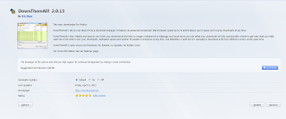
Well.  This looks interesting!

I stare at my laptop like someone disarming a bomb in a bad cop movie (Cut the blue wire!  No, the red wire!  NO! THE BLUE WIRE!)

It's crazy.  Just crazy enough to work!

I finally do what I didn't want to do. I CANCEL THE DOWNLOAD.  Two hours and a Gigabyte of data are flushed over the side. 

I install DownThemAll! and try the download again.  I special, different download manager begins, and I restart the whole process again.

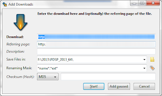
Let's see how this works

A get to about the same point where I aborted before when 5PM rolls around.  I pause the download, shut down my computer, and race home.  Which in Southern California means driving at 20 MPH on a crowded freeway.

Once home, I fire up the laptop again, and restart the downloads on my Fiber Optic line, and start downloading again.


The downloads pick up again, and are done in about a little over an hour.

Once I arrive in Mammoth, I can't contain myself.  I extract the files, and install.

It all works perfectly.  The download manager did the trick!

So what is the moral of the story.  Downloading the information takes time.  There's no denying that, and it can be hard to tie up a system to grab a given file at once.

So if you have a hard time downloading your Autodesk products, try the Autodesk Download Manager, it's worked great for me in the past (I swear).

But if you're running a fancy new version of Firefox, or you have a hard time with the Autodesk Download Manager for some reason (stupid I.T. security policies), try another download manager.  It worked for me, and let me download my Autodesk software, and enjoy my weekend in Mammoth!

If you're running Google Chrome, it looks like they also have download managers available, although I've never tried them (click here for the link).

I wasn't able to find one for you I.E. users.  Sorry.  :-(

Got a thought or two?  Have a download method you prefer?  Share a comment.

BTW, I'm hoping for a video tip by the middle of the week!

Sunday, April 08, 2012

Autodesk Showcase 2013 - A Preview of a New Interface

Find the good. It's all around you. Find it, showcase it and you'll start believing in it.
Jesse Owens

A few days ago, I pulled the cover off my Autodesk Showcase 2013 installation, and took it for a test spin.

The first thing I found when I took a look, the user interface has changed.  It's subtle, but it is significant. 

There a new "Task UI" that's been added.
It's called the "Task UI", and it contains many of the functions normally accessed via hotkeys and pulldown menus.

The pulldown menus are also hidden now.  Although you can click on the arrow at the top of your screen to show them again.  All the hotkeys from Showcase 2012 are still there too.

The menus can still be viewed.
My "knee jerk" reaction was much the same as a lot of us.  I'll have to learn a new user interface. 

But I tried it for a little while, and I've found that it's not that bad.  It wasn't that long before I was starting to get used to it, and (gasp) starting to like it.

So here's a quick video I put together on the new UI.  It's just a preview.  But as I dive further into Showcase, I'll be sure to post some more!


Taken a look at some of the new features in Autodesk Showcase 2013?  Share you thoughts and drop a comment!