Last week, my post showed how the orientation of a model could be changed as it was being imported into Autodesk Showcase. (You can check out that post here)
But what if the file has already been imported? Marion Landry of Autodesk shared a tip via the video comments that pointed it's possible after import too! It's definitely a valuable little jem of a tool I didn't know was there!
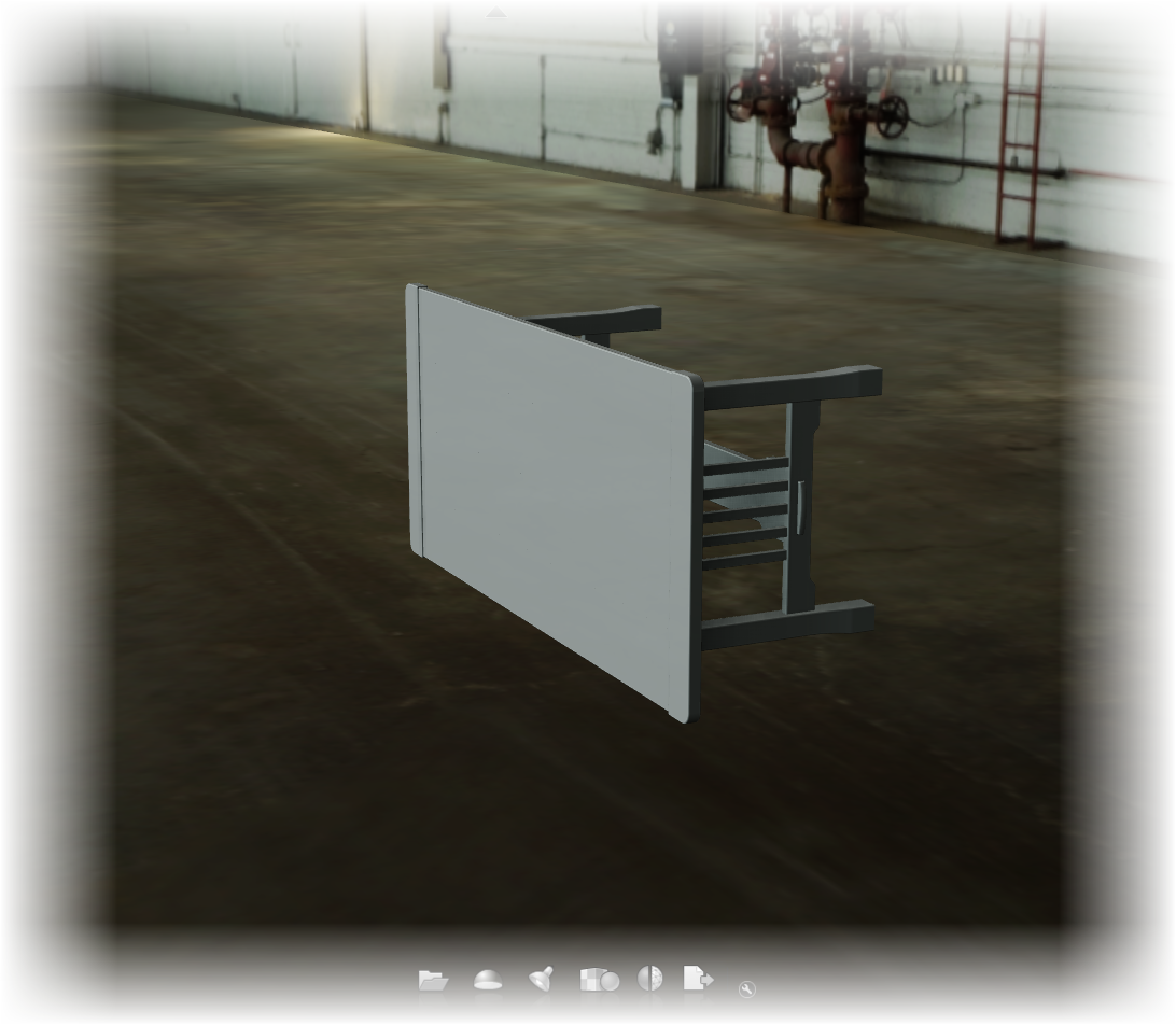
I'm starting out with my model already imported sideways. So there's no chance for me to fix it using the methods I used in my previous post.
It's in sideways, and now how to fix it?
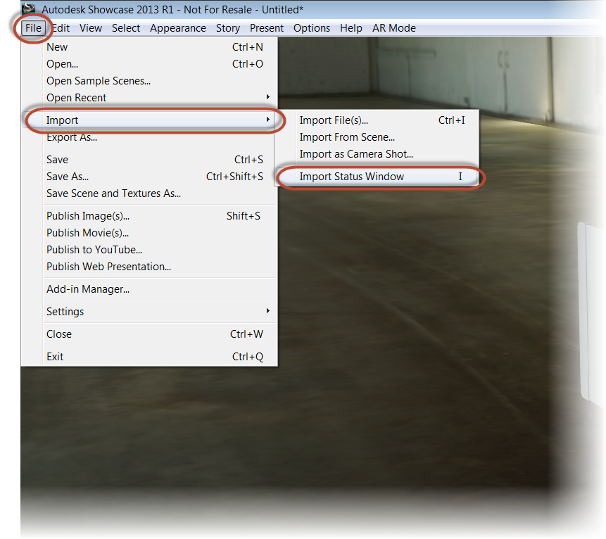
But to fix it afterward, all I have to do is go to the File>Import>Import Status Window menu, or just hit the "I" key.
Locating the import status window
Once the Import Status window appears, I'm going to right click on the name of the imported model under "Source Files". Choose "3D Model Properites.
It's important to right click on the imported , or 3D Model Properties won't appear!
Now, I get the "Original 3D Model Properties" dialog, where I can change the units, and the "Original Up Axis". Choosing "+Z", the model is reoriented!
So there it is, a quick way of changing orientation after a model is imported. Thanks to Marion for taking a few minutes to show this valuable tip!
Sometimes a that clanking sound I hear is a wrench hitting hitting my proverbial works.
And when importing files into Autodesk Showcase from another system, the import orientation (or disorientation), can be that wrench.
Take this for example. Sometimes a file imports, and instead of being right side up, it's completely on its side.
Blast it!
The easy way to fix it is to use the Transform Handles in Autodesk Showcase to correct the problem. But what if there are positional alternatives that need to be preserved? Rotating with Transform handles can sometimes mean rebuilding the alternatives.
Rotating with Transform Handles is sometimes an option
Fortunately, there is another option when importing files.
First, when in Showcase, choose File>Import>Import Files
Preparing to import a file.
When the import dialog box opens, choose the "Settings" button.
Choosing the import settings
Once the import settings dialog box appears, the setting for "Original up axis" can be seen. This is where I can tell Showcase "which way is up".
Note that you can also see the "Import Representations" checkbox in this dialog box. So Inventor representations can be imported in as well.
Changing the orientation
If I take a quick look at the file in Inventor, I can see the +Z-axis corresponds to the top of the table.
Seeing this, I'll choose the +Z radio button, and import the files.
Selecting the +Z option
The file will import, and the orientation will correspond to the "up axis" I selected.
Oriented with representations created as alternatives!
And if you're looking for the usual video that accompanies my blog posts, here you go!
I decided to close this weeks blog with something from the 3D printing world that I found pretty interesting, and not just because of the "high fashion" aspect.
The first time I saw a 3D printing machine was back in about 2000 or so. The material was expensive, fragile, and by today's standards, difficult to work with.
And although I haven't worked closely with a 3D printing machine in years, I'm still fascinated by the technology, and watch with bated breath as 3D printers become more mainstream, and accessible to the average person.
Earlier this week, I ran across an article talking about how the model Dita Von Teese wore a gown that was actually printed on a 3D printing machine.
Go ahead and make your jokes about the article being intereting because of the super model angle........... Okay!
The subject matter aside, the idea that a wearable garment can be printed and worn by someone. Just think of the possibilities.
Need a splint, cast, or sling? Print it!
Does someone need a special harness, mount, or accessory? Print it!
True, the technology may have to mature some more, but it's come a long way already. It's amazing what can be done today, I'm looking forward to what they might be able to do in the near future.
When designing, there are times that alternate positions for components must be shown to ensure the design will perform as intended.
This might be an arm extended and retracted, or a door or drawer opened, and closed.
There are also times those alternate positions need to be shown in a rendered view to properly convey the design intent outside of the design product.
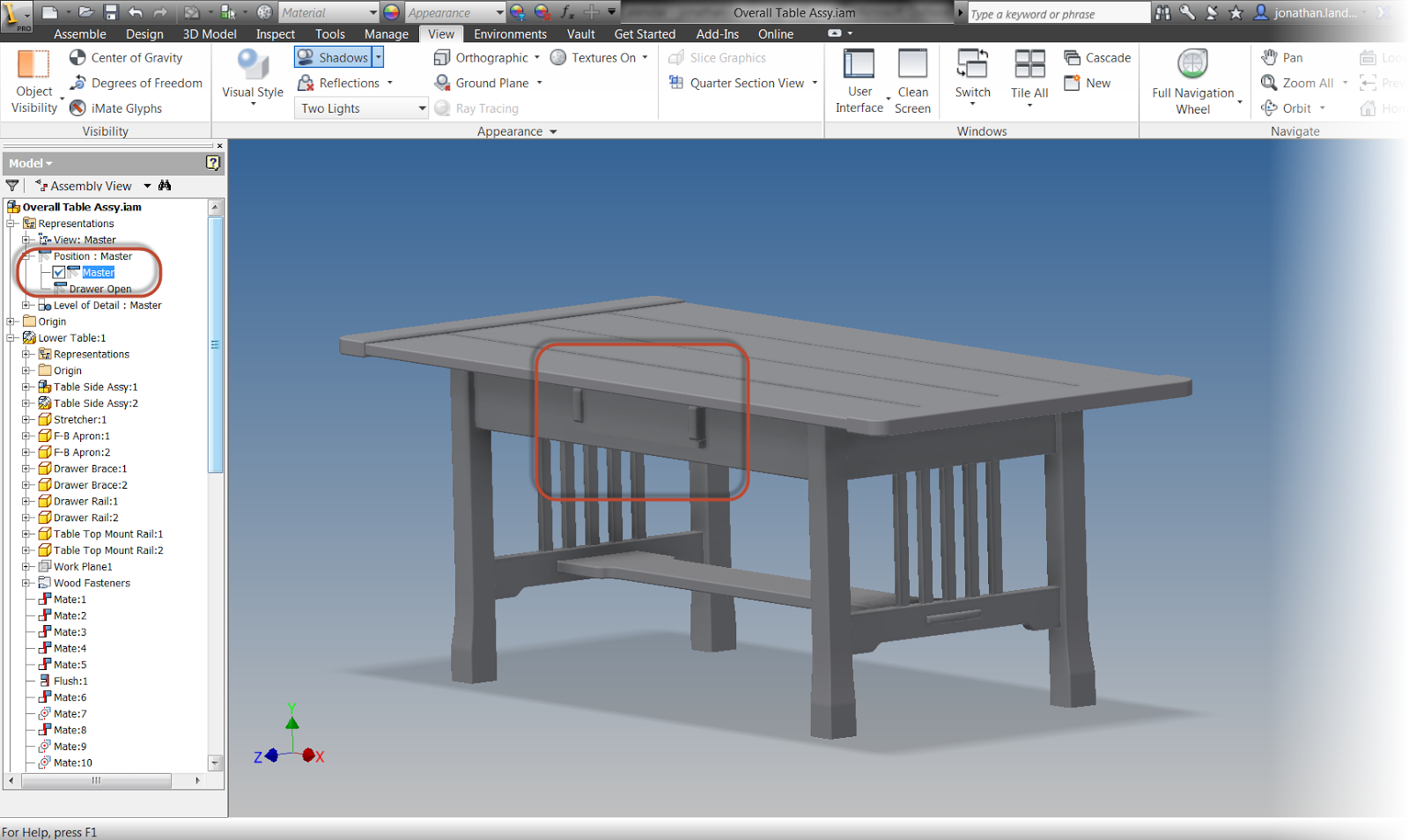
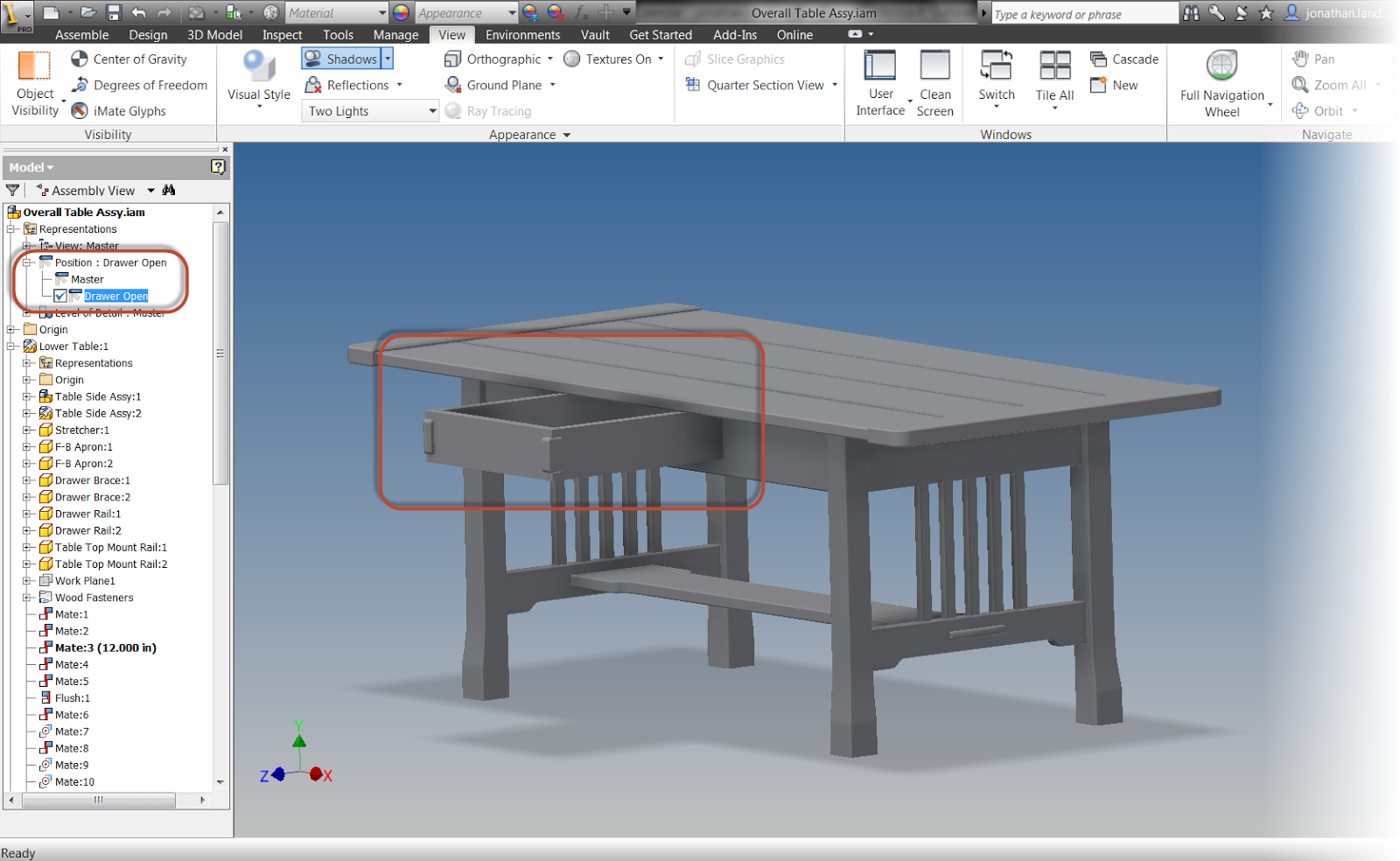
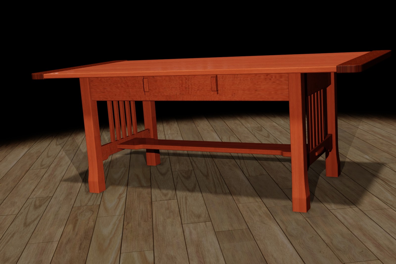
When using Autodesk Inventor, Positional Representations are used to accomplish this task in design. For example, here I'm showing a coffee table with drawer open, and drawer closed positional representation. (For instructions on how to create a positional representation, check out my previous post here)
A positional representation showing a drawer closed
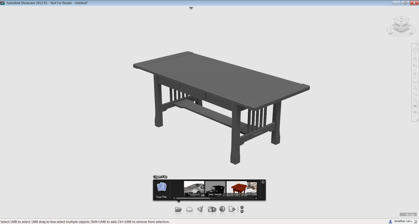
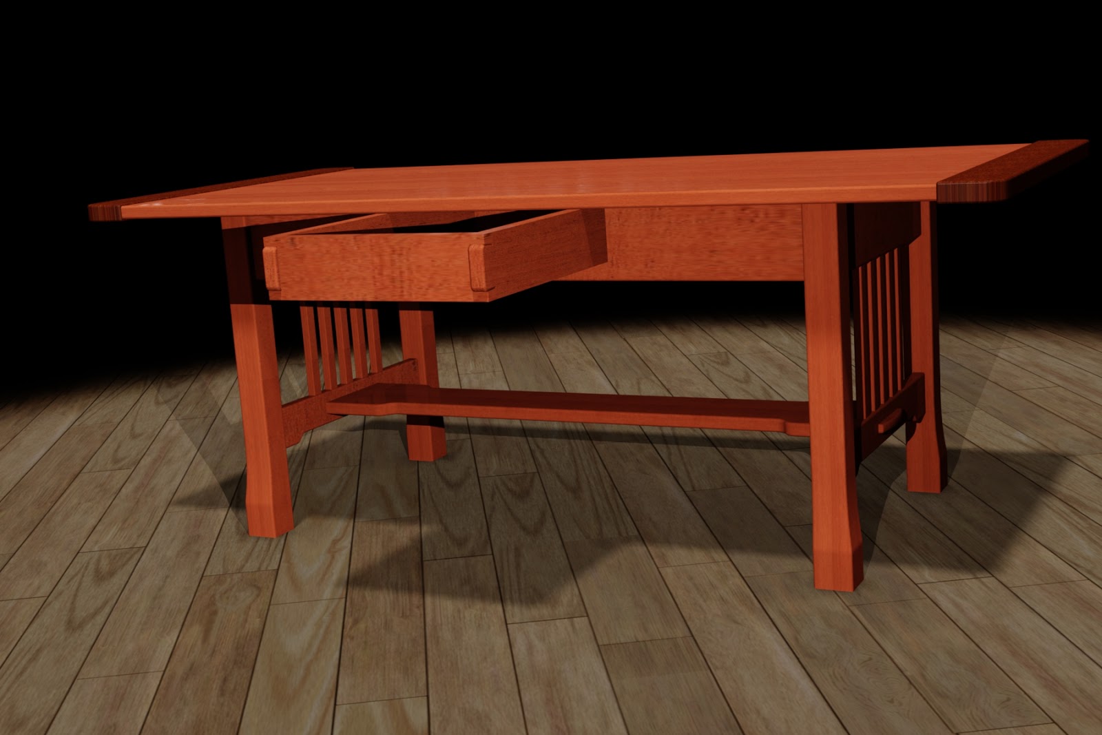
Autodesk Showcase uses Alternatives to create alternate positions for the renderings. Here is the same table shown with alternatives in Showcase
The model is imported and ready with the drawer closed
The alternative with the drawer open is already created.
While each product can work independently and create their own distinct representations of the components, there's no reason to recreate work twice. What if what I want to do is reuse the representations in Inventor, and use them to create alternatives for Showcase?
Fortunately, Inventor and Showcase has a "Suite Workflow" that allows the representations created in Inventor, to create alternatives in Showcase.
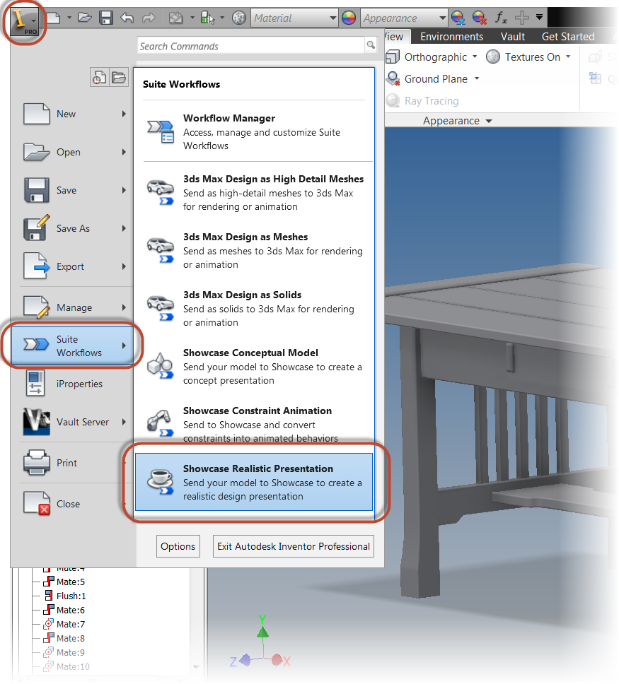
I'm going to begin with my coffee table open in inventor, then I'll click on the Application Icon (The big "I"), I choose the "Suite Workflows", then choose, "Showcase Realistic Presentation".
Starting the representation
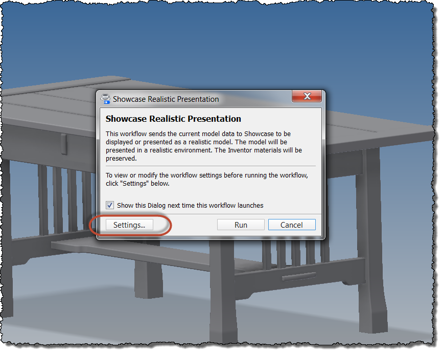
A dialog box appears that describes what this setting will do. I'm going to choose the "Settings" button to make changes to how the model appears on import.
Selecting the settings for import
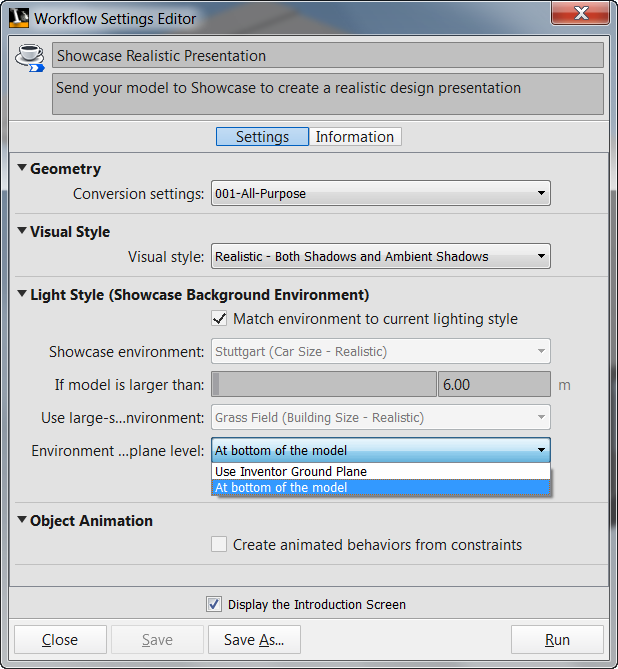
Here the settings for import can be set, such as the conversion settings (the density of the facets making up the Showcase models), Visual Style, and Lighting Style can be set. Most of these can also be set in the Showcase scene, so I take defaults for most with one exception.
I do like to set the "Environment... Plane Level" setting to "At bottom of the model". While your settings may vary, this setting is works best for the models that I create.
Workflow Settings
Now I go ahead and click "Run".
Pulling the trigger and running!
The model will process, and will open in Showcase. Both alternatives are created by the positional representations
Now all I have to do is apply the desired materials and lights in Showcase, and finish creating my model in Showcase. No recreation of the drawer open, or drawer closed. Just use what Inventor provided to Showcase!
A quick rendering in Showcase with the drawer close
The same scene with the drawer open via the alternative.
And to see the steps in a video format, just take a look below!
I wish I could say I had the wherewithal to find every last tip and trick there was to find in Autodesk Showcase. But alas, I just can't quite do it.
One of those items that has always been on my "I'll get to that some day" list is the creation of custom environments. I've always known that there are a couple of tricks to it that I needed to learn, but with so many things, I never got around to it.
Thankfully, while searching one of my favorite Autodesk Showcase channels on YouTube, run by Marion Landry, I found a great video on creating custom environments.
Not only did it answer a lot of the questions I never got around to looking into myself, it also had links to Openfootage.net, which has some great hdr images that can be downloaded and used to create custom environments. And the best part is they're all free (although donations are accepted).
My own environment created from an image on Openfootage.net
So here is Marion's video. Take a look and enjoy. This is one of the best videos I've seen for those of us who want to know how to create custom environments in Showcase.
Today's bonus blog post is a success story for a company called Enviroguard, who make spill containment systems for batteries, such as the ones found in solar, rail, and switchgear applications.
They use the Autodesk Product Design Suite to do all those "buzzwordy things", like "improve efficiency", "increase time to market", "reduce errors". Buzzwords! Ding! Ding! Ding!
And of course, these are all good things we all strive for!
What I really like about this story, aside from it involving the "home team", is how Enviroguard is combining the different tools in the Suite.
They use Autodesk Inventor with iLogic customization to create new designs, Autodesk Showcase to create the visualization for the design, and Autodesk 3ds Max to create very realistic looking instructions for installing the systems.
And finally, Autodesk Vault keeps track of the data as it flows around the system, making sure that design are being used, and reused, as efficiently as possible.
But I'll let Enviroguard speak for themselves with the video below. I think they have a unique approach to create a truly "holistic" system.
But with that table placed into the drawing, there's an additional benefit I think makes this work flow worth considering.
When the Excel table is inserted onto the drawing, it maintains a link back to the Excel file, which make it what many like to refer to as "a single source of truth".
In other words, the Excel table can be updated, and all files looking at that table update as well.
Taking the example I used in my last blog post, I used Excel to create a chart that showed small tools and preferred vendors for a wood working project. I used it as a quick way of inserting standard information without recreating the table.
The Excel table used in my previous blog.
I've taken this particular table, and inserted it onto two different drawings, which will be using the same information, one is the Saturday table I used in last weeks blog, the other, a blanket chest for a different project.
The Saturday Table
The Blanket Chest
For this scenario, I'm going to say that Reed Wood Supply has been purchase by "Blue Sun" (who recognizes that movie reference?).
I'm going to stick with them as a vendor, and just swap "Reed Wood Supply" with "Blue Sun".
To do that, I open up my Excel table, and make the changes. I can do this in one of two ways.
The first is to just open the Excel table up by browsing to it from Excel, the other is to locate it's link in Inventor's browser, right click, and choose "Edit".
Browsing to the File in Excel
Right Click and Edit in Inventor's browser.
Either way, I can now modify the file and save it.
Changing to "Blue Sun"
Once saved, the tables will update to reflect the new changes in both drawings.
The updated table
I've noticed that when I right click and choose edit from the browser, the table may not refresh right away. If that happens, right click on the table, and choose, "Update" . After that, all should be as it should be.
Updating the table manually.
There is one other capability of this method I find intriguing If the table is edited like an Inventor Table, additional rows can be added to the table for a particular drawing. However, these rows that are added don't propagate back to the Excel table.
I like the thought of this because if a particular project uses mostly the same "common" table items, but has a few that are unique, I can stick them onto the end of the table, and getting the best of both worlds.
To accomplish these steps, right click on the table and choose edit.
Next, right click on the edge of the border, and choose "Insert Row".
Now enter the desired values and repeat as needed. In this example, a different finish is being used on the Saturday table, so I've added a finer grit sandpaper and spar varnish to the vendor list. Since the table was edited in Inventor this time, only the drawing where I made the edits is changed.
The rest remain the same, allowing me to keep common what I want to keep common, and add where I need to add.
The two tables compared to their Excel source. Notice the added items on the top table.
So that's it. Utilizing the Excel table as a single reference, and making edits to accomplish different results. I do like some of the things I see here, and I think I'll utilize this more in the future.
I hope you can to.
And to wrap this up, check out the video on this work flow below!
Technology marches on at an alarming rate sometimes, as a matter of fact, probably faster and faster every day.
I remember when looking up directions meant using a paper map. I recall when "dropping a dime" actually meant dropping a dime into a coin slot on a pay phone, and when sending mail required the use of pen and paper.
Now, just today, I simultaneously setup software on computers in Dallas and Pennsylvania without leaving my chair in Southern California. After completing that, I used my phone to get directions (with live traffic updates), and drove home while simultaneously chatting with a friend in Arizona.
Times have changed.... And I do find myself wondering what technology the kids of today will see unfold in their lifetime.
Tonight I stumbled onto a video of what a student is doing with the Autodesk Technology 123D Catch.
All I can said is: "Wow".
If you don't know what 123D Catch is, it's a technology that lets someone take multiple pictures of an object, and stitch it into a 3D model that can be used for creating concepts, presentations, and event 3D printed models.
But I'll leave it to the video to describe. The student creating the models, Ehsan Noursalehi, shows how much an imagination person can do with new technology. I especially like how he uses Mudbox and 3dsMax to make the most of the scanned object!
It surely inspires me! I hope it inspires all of us!
Last week I found myself working with tables in Autodesk Inventor drawings, and realized that I'd forgotten a nice little capability drawings have. Among being able to import tables and parameters from parts and assemblies, as well as iPart and iAssembly tables, they can (insert drum roll) also import a list directly from Microsoft Excel.
The first question one might ask is simply, "Why?" Why keep a table in Excel, instead of creating it directly inside of Inventor?
While they may not apply to everyone out there in the "Verse", I think they're still reasons to consider.
1) Does the person creating the tables know Inventor? What if the Excel tables are maintained by someone who doesn't know Inventor, and doesn't need to know Inventor
2) What if I want to use calculations in my Excel chart?
3) What if the Excel chart is one of a few different standard tables, any of which can be inserted into a drawing based on the need of the product produced by the drawing.
So if a reasons such as this applies, here's how that Excel Table can be brought into Inventor's drawing:
First I have the model who's drawing I'm going to work with. It's a small wooden end table designed to be built on a Saturday, hence it's name "Saturday Table".
The Saturday Table or "Project"
And to prevent confusion between the "Saturday Table" and "Excel table". I'm going to refer to the "Saturday Table" as "project" from this point forward!
For this project, I have a table of small tools I'll need, such as router bits, sandpaper, and so on. I'm going to put this on the drawing for a reference to which tools I need, and which vendors I prefer.
The chart in Excel
The drawing where the table will go
The first step to insert the table onto my drawing, is to select the "General Table" icon on the Annotations tab.
Finding the icon
The Table dialog box opens up next. Choose the "Browse" icon to start looking for a file to import.
Begin Browsing for a file.
Notice the file types to import. In addition to Inventor models, the Excel formats, *.xls, *.xlsx, and *.csv are included. I'm going to choose my Excel file "Vendor list.xlsx", and choose open.
Choosing my Excel table
With the file selected, I can choose my options for the chart. Notice the Start Cell and Column Header Row settings? I changed these to reflect the information in my Excel table. My data, the information about the tools, starts in cell 'A3'. The names of the columns, that is, the headers, is located in row 2.
Setting up the table import
The table now is placed on the drawing. The image below shows the table as inserted, without any changes.
The "as imported" table
I do have to change the title of the table, as I have yet to find a way to import it from Excel. I can also stretch the cells by dragging their borders to get them to appear the way I'd like them to. To get even more formatting tools, right click on the table and choose "Edit".
The cells have been stretched by dragging, right click to edit the format
When the edit dialog opens up, I'm going to select the "Table Layout" icon, indicated in the image below, and change the Table's title. I'm also going to move the header to the bottom of the table, and reverse the direction of the list so I can dock it on top of my title block.
Changing the settings
And done!
And of course. There has to be a video! So for the video, see below!
This week is a short tip, due to some required domestic repairs around the house. A gate pulled out its hinges, so a big part of my blog time was spent fixing that.
Time to get busy!
All that's left is the painting!
Fortunately the gate is repaired, except for a little paint, and there's still some time left for blogging!
So here we go!
One tip that I've always thought was helpful was how to set Autodesk Inventor's drawing settings to get the crispest shaded view possible. It's one of those settings I usually check right away.
Sometimes, when zooming in closely on a shaded view, the colors appear blurry. It's almost like water colors were used to create an artistic effect. In this example using the section view of a bicycle fork, the colors can even run into each other, making it more difficult to see the components clearly.
The bicycle fork used in this exercise.
The colors bleeding together on the drawing. It would be nice to clear these up.
Fortunately, this isn't a difficult setting to change.
First, find the "Tools" tab, and choose "Document Settings".
Finding Document Settings
On the Document Settings dialog box, choose the "Drawing" tab. On this tab will be a section simply called "Shaded Views". Change the "Use Bitmap" option from "Always", to "Offline Only.
Changing the setting.
Click okay, and check out the section view. Much better!
A crisper looking shaded view
There is one more tip, however! If you want this setting to be used in all future drawings, check the drawing templates and make sure the setting is changed there! This will make sure any new drawing is using the desired shaded view setting!
And of course there has to be a video to go with it! So below you'll find the video version of the tip.
And one more video, purely for fun! Here's a video of the Planes of Fame F-86 Sabre and Mig-15 flying formation at the Living History Event on February 2nd. The camera perspective is really cool! I thought it was really interesting to see the leading edge slats on the F-86 working!


