Find us on Google+ Inventor Tales

Monday, August 05, 2013

A Quick Trick - Selecting All Occurrences in an Autodesk Inventor Assembly

I have called this principle, by which each slight variation, if useful, is preserved, by the term of Natural Selection.
Charles Darwin

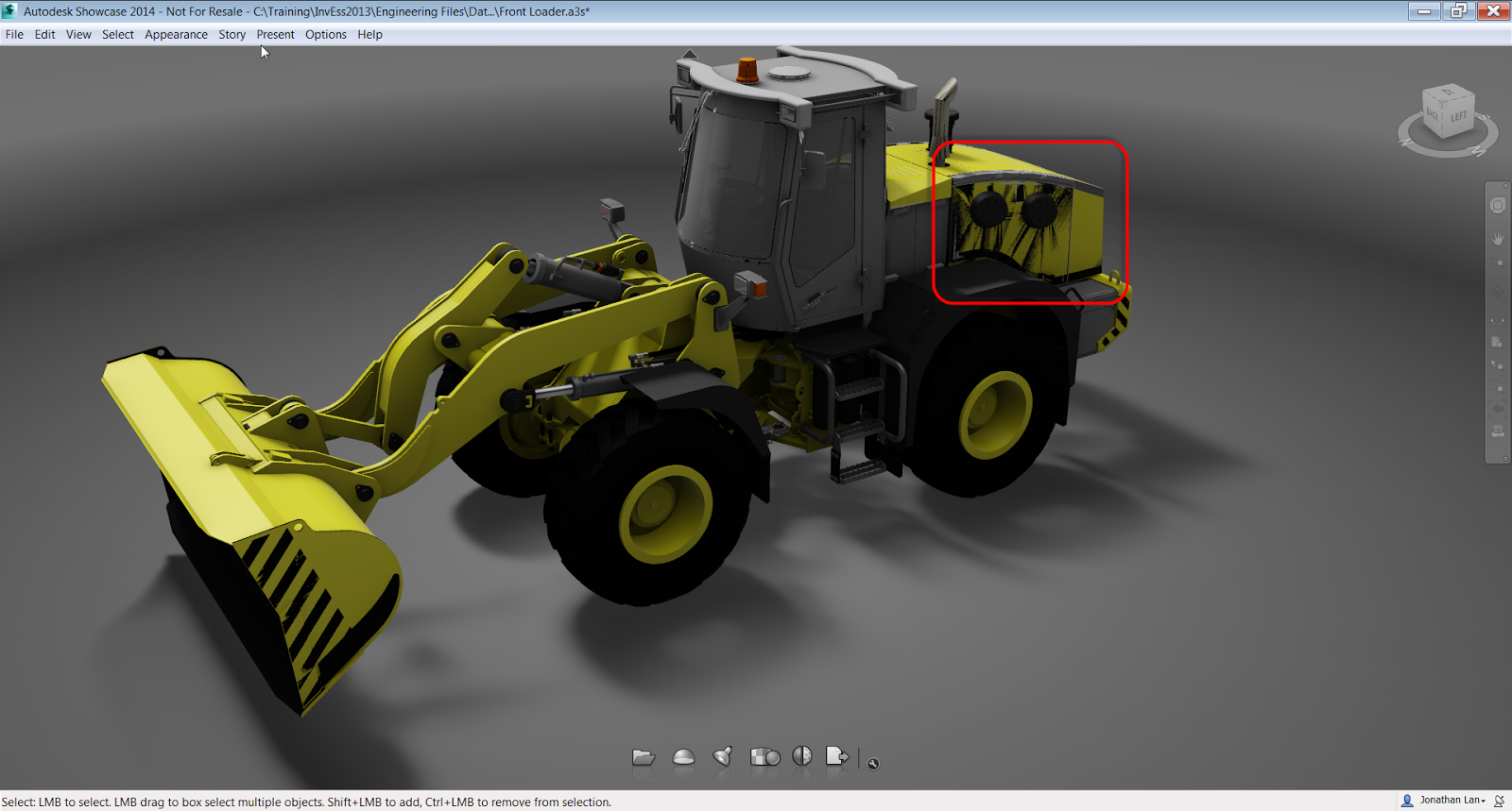
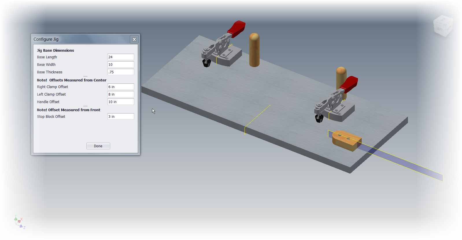
Note: The assembly I was working on today isn't one I'm free to share, so I'm using a "stunt assembly" as a stand in.  Bear with me!  

I'm still out here working far from home in Minnesota, where I'll be the rest of this week.  And while I don't have time to create any big posts, I can post a quick tip for today.

One I used just today.

I was working on an assembly that had several components that were very similar.  They looked so close that they may have been a second copy of the same component, or a different component entirely.

To make it even more interesting, there were several components that were similar, so it wasn't even an either or, it was one of many.

So how can I quickly determine which components belonged where? 

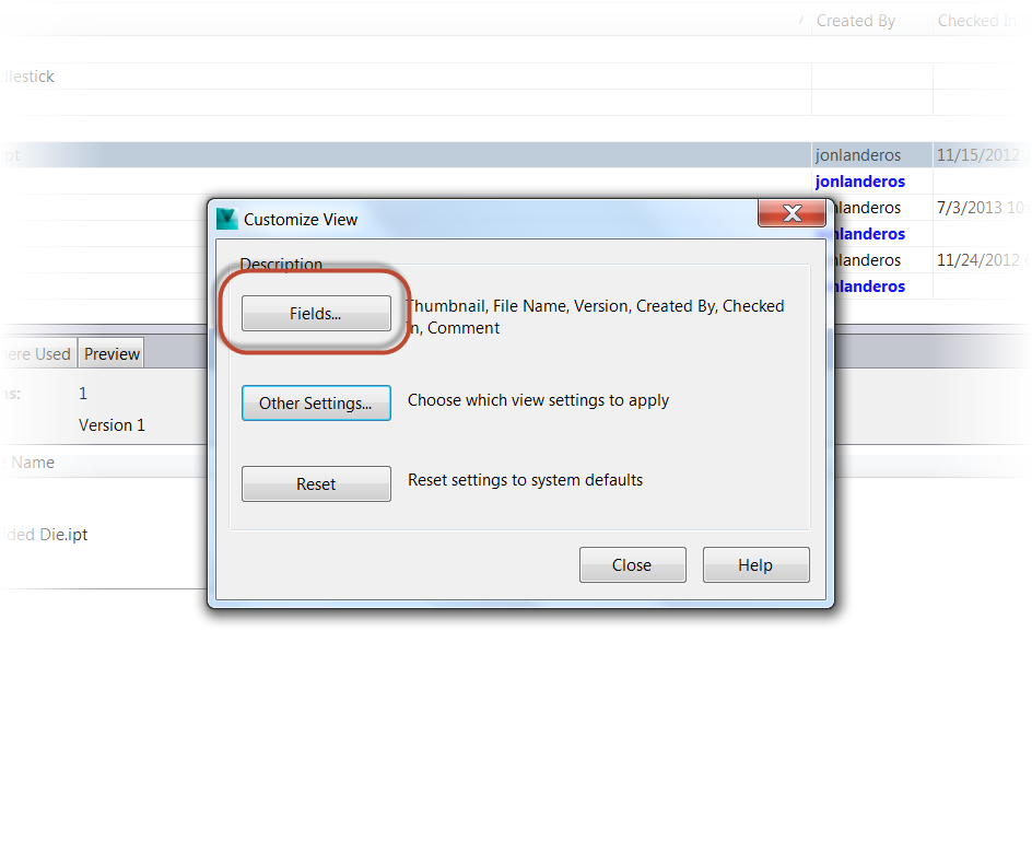
Sure, I could go into the Assembly Bill of Materials and see how many instances of the component I see, and while that works great, it doesn't always give me what I need.

One way of checking how many components there are in an assembly.
So what's a quick alternative? 

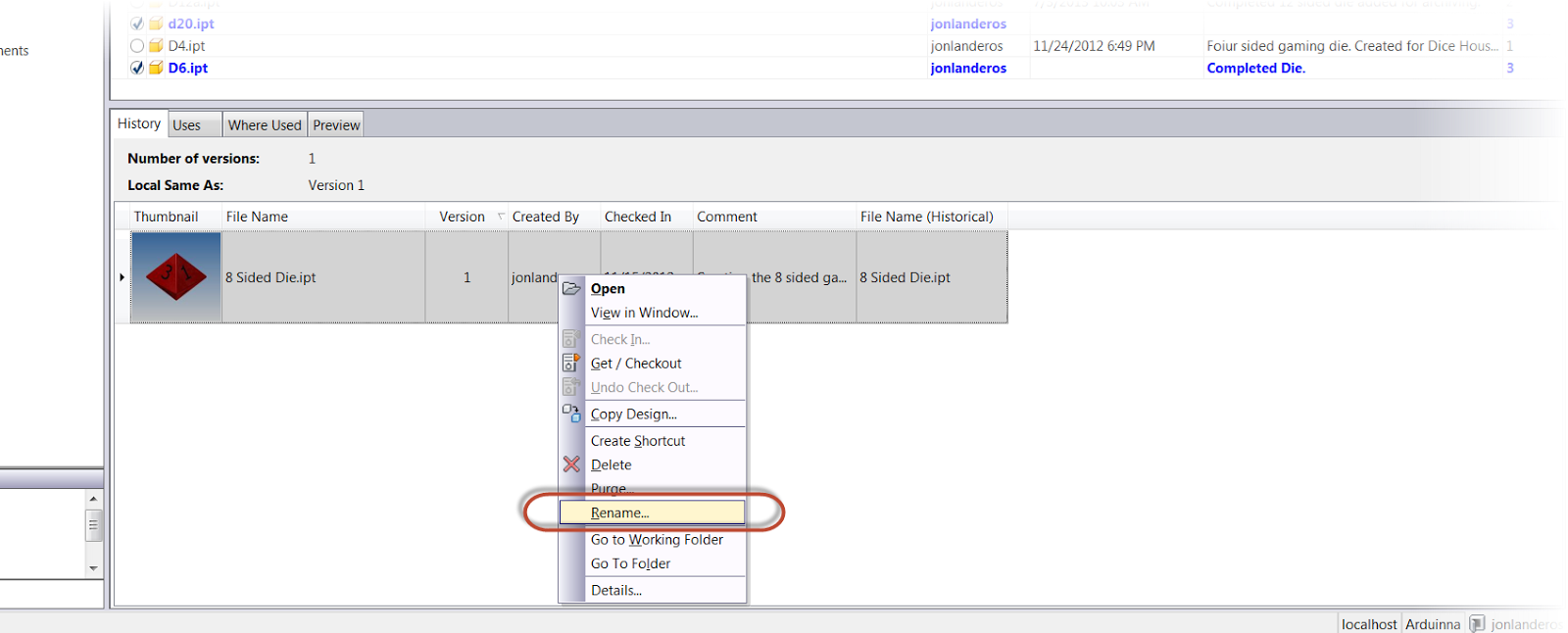
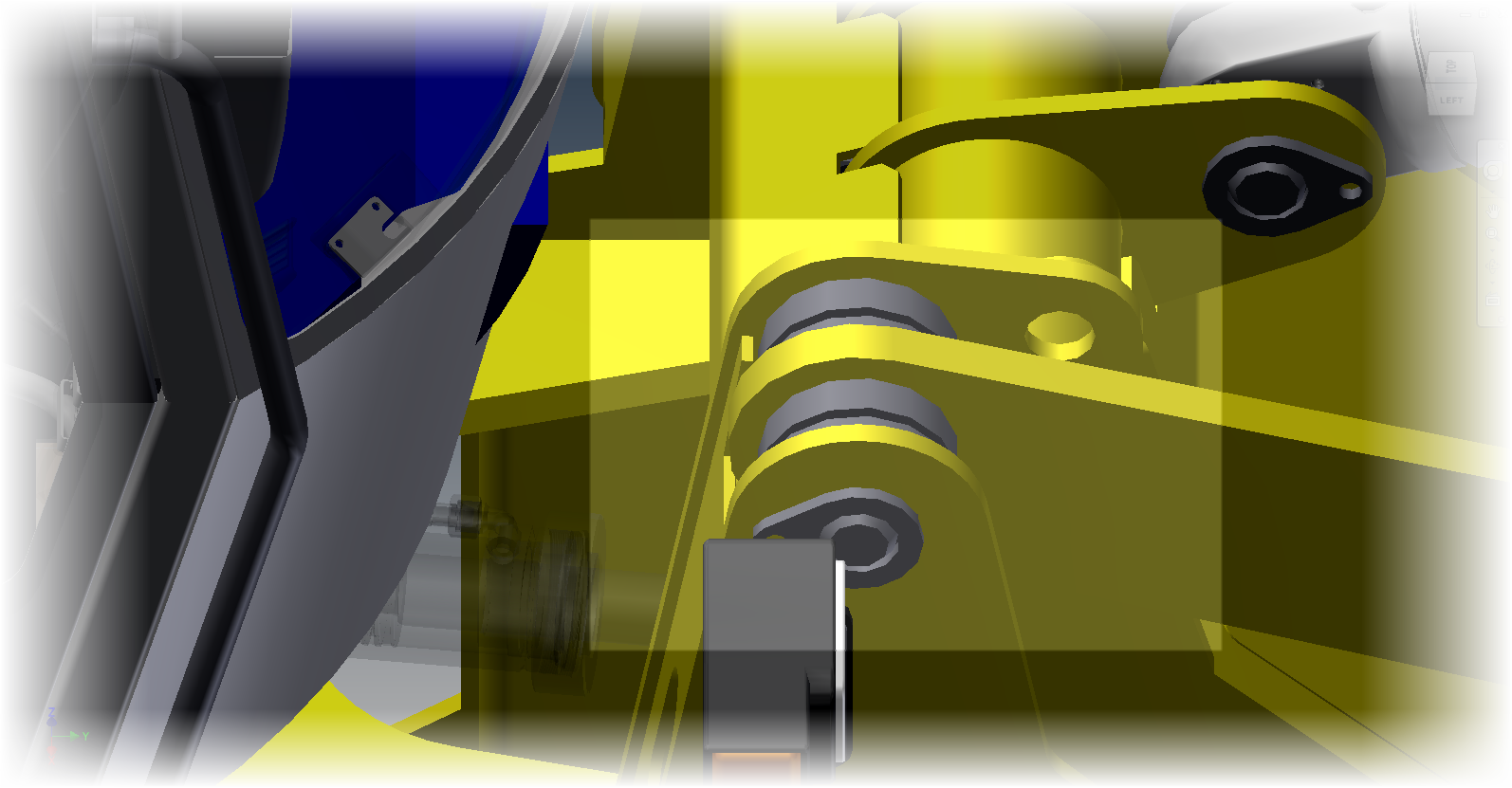
I'm going to right click on one of the components I'm curious about, and choose Selection>Select All Occurrences.  Just like I've done with the shock assembly pictured here.

Right clicking and choosing "Select All Occurrences"


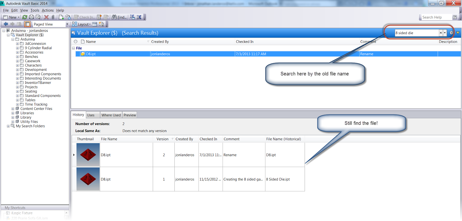
This will select all copies of of the same component on screen.  This quickly tells me how many components are similar visually, without leaving the modeling window.


Both assemblies highlight, telling me they're the same assembly placed twice

Now I can see that both shocks are actually the same assembly used twice, instead of two very similar, but different assemblies.

As an added bonus, I can now change visibility, delete, and replace the components, among other commands, because I've already selected the components I need.

To be fair, I'm not saying this isn't a replacement for other methods, like using the Bill or Materials to check how many components are in an assembly, but what it can do is check to see if "this component is the same as that component", when a quick check is needed.

So give this a try and add it to your bag of tricks.  When I was working with that assembly today, it was a big help! 

Sunday, August 04, 2013

A Blog Delayed this Week.

I had high hopes for writing a post this week!  But I had to take a business trip to Minnesota, and due to a couple of delays, I got in just late enough to clean up and get to bed!

So look for a post a little later this week!

And to hold you over, here's a video of the Planes of Fame F4U Corsair starting and flying from this weekend.

Apologies for the shaky camera work.  It was the best I could do with my little point and shoot camera! 

Thursday, August 01, 2013

Getting Rid of the "Black Streaks" in an Autodesk Showcase Scene

I believe in the kingdom come
Then all the colors will bleed into one
U2 - "I Still Haven't Found What I'm Looking For"

Sometimes, there really is "one magic" setting that can obtain the desired result.  In Autodesk Showcase, I've found that one of these is setting the clipping plane.

Sometimes, when a model is imported into a Showcase scene, black triangular streaks will appear across the model.

What are those?  They're not supposed to be there!


They shouldn't be there, they're not right, and they're ugly.

They're actually caused by Showcase not being able to sort the faces.  The back face is actually bleeding through the face in front of it.

Fortunately, they can be easily cleaned up with just one setting.
 

The setting is found in File>Settings>Scene Settings


Getting to the setting I need

Once the dialog box opens, the setting I'm after is: Distance from camera to near clipping plane:

The setting to change is highlighted.
By increasing the number, the distance to the clipping is changed and the faces can set the correct order.


Much better!

In this case, increasing the setting to 2.000cm makes everything as it should be.  Of course different scenes may require different settings, so if you if you're working with your own scenes, you may have to try a couple of different numbers.

But just that setting alone, can make a huge difference in how a Showcase scene appears in the end.

For a fantastic explanation of this, take a look at the video below created by Marion Landry.  She's the person who originally taught me this great trick, and she's definitely got the definitive video in my opinion! 


Sunday, July 28, 2013

An Introduction to Autodesk Configurator 360

You're giving a gift, so finish that process. If you configure it for them, your sweat is in it.”
Alfred Huger

Back on July 9th, 2013, Autodesk announced Autodesk Configurator 360.  It's a cloud based configurator where Autodesk Inventor files can be hosted and configured given parameters and iLogic rules online. 

All that's required is to upload a model to Configurator 360, select the desired options, and release it into the wild.  There are even options to control who can access the configuration.

So with all this cool stuff, how is Configurator 360 accessed?

First, you need something that can be configured.  In this example, I'm using an assembly powered by iLogic.

This is a template for a router jig for use in wood working.  This is a template that can be copied, then modified to fit the part it's going to cut.  The iLogic rules drive the size of the base, and the position of the handles and stop on the base.


The router jig template, showing the iLogic form that drives it.


Next,   access to the Configurator 360 site is needed, which isn't difficult, a 90 day trial can be obtained here. 


The Configurator 360 site

Once a trial is obtained, I can go ahead and log into Configurator 360 site, I'm going to take this folder, in a zipped format and upload it to my Configurator 360 site.

I upload my design by choosing the Designs tab, and clicking the New Design icon.

Adding a new design to Configurator 360


The screen to upload the file will appear. I'll have the option to name the project, choose a format to upload the files in (*.iam, zipped *.iam, ipt, or zipped ETO). 

Adding an assembly to Configurator 360

Now, all I have to do is click the upload icon to upload the file to Configurator 360. Note that at first, the webpage may have to be refreshed to get the files to appear.


Once the webpage is refreshed, the Configuration appears, and it can now be edited by selecting the icon in the picture below. 


The first tab that appears is the "Access" tab.  This tab provides a place to change the display name, create a description, and control access permissions to this particular configuration.


Clicking on the Parameters tab, options to control parameter name, order, and if a parameter is read only or not can be set here.  Here, parameters can be set to read only, or minimum or maximum values can be set.


Now, that this is accomplished, I can make the configuration available. for users, where they can change, values, and download files as needed, to make use of the configuration that has been provided to them via Autodesk Configurator 360.


So have a look at the configuration I created at the link here, and see for yourself if something like this might be helpful to your business..

If it is, have a go at the free trial on the Configurator 360 site!

And take a look at the video below!


Sunday, July 21, 2013

Points for Style - Creating an Offset Workplane and Sketch in One Step in Autodesk Inventor

“You can't do sketches enough. Sketch everything and keep your curiosity fresh.”
John Singer Sargent

Some of my favorite tricks in Autodesk Inventor are the simple ones.  They may not be flashy and they may not save hours of time, but they're nice little tricks that just make the day to day operations flow by a little smoother.

One of these, is the ability to create an offset work plane and sketch at the same time.

Typically, to create a sketch on an offset work plane there are a few clicks involved.

First, I have to start the work plane tool, and create my offset work plane.

Creating the workplane

Next, I have to place a sketch, on that newly created work plane.

Creating a sketch on that work plane

There aren't a lot of clicks involved, but it's always nice if there's a way to do it with even fewer clicks. 

How can that be done? 

Instead of going to the Work Plane tool, I'm going to start the 2D Sketch tool directly.

By clicking and holding on the planar face I want to offset from, I can drag the offset work plane, and create both the sketch, and the plane at the same time.


It's a simple thing, but it really does make things flow a bit more smoothly.

Give it a try! 

And take a look at the steps shown in the video below!


Sunday, July 14, 2013

Making the Work Plane Tool in Autodesk Inventor "Stick" and Stay on Until You're Done!

“The possibility of stepping into a higher plane is quite real for everyone. It requires no force or effort or sacrifice. It involves little more than changing our ideas about what is normal.”
Deepak Chopra

Today is a quick blog post.  I broke my routine today and took a road trip to Camarillo, Ca.  and cruised a picturesque little town from my childhood. 

I also took some time with the Southern California Wing of the Commemorative Air Force, and saw a few of the incredible aircraft they have at their facility.


Here are just a couple of the aircraft that make their home at Camarillo Airport.

d

A Curtiss C-46 Commando (yes that's my finger in the picture)

A Griffon powered Spitfire MkIV. 


It was a nice change of routine, but it did hurt the blog post!    But nonetheless, here is a short post!

One setting I love to change in Autodesk Inventor is the default behavior for work features like Work Planes, Work Axis, and Work Points

In Inventor the default behavior is to place one work feature, then exit the tool.

So if you want to place more than one, you have to restart the tool and place the next work feature.

What many users out there may not know, is that this behavior can be changed.  There's a way to make the tool "stick"  so as many work features can be placed in succession without having to restart the tool every time.

In order to make the tool "sticky" use the steps below.  I'm going to use a Work Plane, but it's the same steps for Work Axis and Work Points.

1) Start the tool.  In this case, Work Plane


Starting the Work Plane Tool.
2) Now that the Work Plane tool is active, right click and choose Repeat Command.  Make sure the option is checked as shown in the screen shot below.


Make sure Repeat Command is checked


And it's all done.  This setting will stay on until it's changed, and from this point forward, the Work Plane command will stay active until cancelled.


So give it a try and see what you think.

And for the video portion, here it is below!


Thursday, July 11, 2013

Autodesk Configurator 360 - Something new from Autodesk

“You're giving a gift, so finish that process. If you configure it for them, your sweat is in it.”
Alfred Huger

Today, it's just time to talk about something from the news desk. 

As of yesterday, Autodesk has released Autodesk Configurator 360

This cloud application allows the user to upload Autodesk Inventor components, select key parameters, and let someone, such as a customer, configure the components via a cloud application. 

It's brand spanking new, so new it's still got that "New Software Smell".  So I can't say that I know all of it's ins and outs.  But here's a video to take a look at. 


It comes with a 90 day trial, so it might just be worth taking a look at! 


Sunday, July 07, 2013

Recalling an Old Filename for a File Renamed in Autodesk Vault

History will be kind to me for I intend to write it.
Winston Churchill

One of the nicest functions of Autodesk Vault is the ability to rename a file easily, as well as track the versions of files, and the history of files. 

But what happens if after renaming a file, it becomes necessary to recall the previous name?

Fortunately, Vault as a field designed for just this purpose.

It's called: File Name (Historical)

When this file is added to the Preview Pane in Vault, the old file name (before it was renamed) will be seen.

Now that we know that, how is the field added to Vault Explorer?

First, right click on the title bar in the Preview Pane, and choose Customize View.  Don't use the Browser Pane.  This one only shows the current file, and it's the files in the past we're after.


Customizing the view

Once the dialog box appears, click on the Fields icon.

Click on the Fields icon


Locate the File Name (Historical) field and add it to the title bar.


Locate the field and click Add
The field will move to the right column

 Once the field shows in the dialog box, click OK to close the dialog box, and click Close on the dialog box after that.

The and the field will now show in the title bar.


The field showing in the pane

But since the file "8 Sided Die.ipt" only has one version, there isn't much to see.  However, now I'm going to rename the file to "D8.ipt" to match the naming convention for the other dice I have in Vault (D4.ipt for a 4 sided die, D6. for a 6 sided die, etc.)

To rename the file, I'm going to right click on it, and choose Rename, and step through the wizard to rename the file.


Right clicking to rename the file.

To see all the details for renaming a file in Autodesk Vault, they can be found in my earlier post here.

Once the file is renamed, I'll see two lines in the Preview Pane.  The File Name column will show the current file name, but the File Name (Historical) field will show what the name of the file was before! 

The history is visible, right there!

And for one last tip, try searching for the old file name.  Since Vault still remembers the history, the file can still be located by the old file name!

Searching by the old file name
And now, for the same steps in a video version, take a look at the video below!

<iframe width="545" height="409" src="//www.youtube.com/embed/A1GbPbtn7zo" frameborder="0" allowfullscreen></iframe>

And on a final note, if you're interested in the dice models that are used in this example.  You can find them at my GrabCAD site here!  

Sunday, June 30, 2013

Conditional Feature Suppression in Autodesk Inventor - Turning a Feature On & Off Automatically

“Some have courage in pleasures, and some in pains: some in desires, and some in fears, and some are cowards under the same conditions.”
Socrates

Sometimes the challenge I encounter isn't knowing which tool in Autodesk Inventor to use, but which tool is best for a given situation.

For example.  Not that long ago, a challenge arose.  I had a part that was going to change size. 

When the size of the part changed, there was text that also needed to change to reflect the changing dimension of the part. 

Here I have an example I've created for this blog.  It's of a common wood working tool called a bench dog.

It's a pin, often (but not always) with a square head.  It slides into holes in the workbench and clamps boards from the side for working. 


Bench dog image courtesy Wikipedia


The head has dimensions of 1 inch square, and 1.5 inches square.  I've created text that will identify the bench dog.

The 1 inch bench dog
The 2 inch bench dog.  Different text, with a larger height is used.


Both the height of the text was going to change, and the text itself was going to change. 

I'm not savvy enough to get into the API and alter it using VBA.   But after reading Bob Van der Donck's blog here, I found a little inspiration. 

 Why not just create multiple features, and suppress them based on the dimension that was changing.  

Below is an example.  Notice that the 1 inch text is suppressed.  It only shows red on the part because I've selected it, and it's previewing for me. 

The "1 inch Bench Dog" text is suppressed.

For what I was doing, it would work! 

I could always us iLogic to suppress the features in question.  It's a simple enough operation for someone familiar with iLogic

But we wanted to avoid iLogic, so the parts could be kept as simple as possible, and could be reproduced by someone familiar with Inventor, but not necessarily iLogic.

And so the "brain-wracking" began.  How can I make this happen,without iLogic.

Then I had my AHA! moment.  Inventor has a tool called Conditional Feature Suppression

What does Conditional Feature Suppression do?  It suppresses a feature based on a dimension!

It's perfect for my case. 

My first step, was to rename the parameter defining the head size of the bench dog to "Dog_Width".  I also made this parameter a Multi-Value list with the values of 1.0 in and 1.5 in.

Creating the Multi-Value List


Adding the values to create the list.

The Mutli-Value list appears as a pulldown
 With the parameters created, I located the 1.0 inch text in the browser, right clicked, and chose Properties.


Accessing the dialog box for Conditional Feature Suppression
One the Properties dialog box opened, I checked the If check box, selected Dog_Width in the pull-down menu, and set the rule so the feature would suppress if the Parameter was anything other than 1 inch.

The options I've selected for the 1.0 inch text.


Now all I had to do was repeat the same steps for the 1.5 inch text, telling it to suppress if the Dog_Width parameter was not equal to 1.5 inches.


The settings for the 1.5 inch text.


And I'm done!  Editing the parameters and toggling between 1.0 inches and 1.5 inches will both change the size of the bench dog, and suppress and unsuppress the appropriate text!


Selecting the 1 inch face size:

Changing the dog.  Note that I've changed filters to shrink the parameters dialog

Selecting the 1.5 inch face size:
The 1.5 inch face.

So go ahead and take a look at Conditional Feature Suppression.  I know there are many out there who love iLogic, and will say that this could just as easily be accomplished with a few lines in an iLogic rule.


And that's true enough.  I'm not trying to say that iLogic isn't appropriate for this.

But what this gives is an option.  The ability to accomplish the same thing without using iLogic and sticking to tools that may be more familiar to the average user than iLogic.

Hey, there's no reason this couldn't be used in conjunction with other iLogic rules! 

So keep this in your bag of tricks.  It may prove helpful someday! 

And as always, check out the video version of this below!

Thursday, June 27, 2013

Released into the "Wild" Autodesk Fusion 360 is Here!

“Fusion will be the final way out for the future.”
Shen Wenquan

Earlier this week, Autodesk announced Autodesk Fusion 360, a cloud based mechanical design tool.

So what does this exactly mean? 

Instead of a heavy 3D modeller sitting on top of your workstation, now you're operating on the cloud. 

The files are stored in the cloud.  In that ethereal world of 1's and 0's, designs are shared, collaborated upon, and versions are tracked, the whole time the design is being created, or "ideated",to use the popular buzzword

In this respect, it reminds me a bit of how I've been storing documents on Google Drive for years.

There's also a nice dashboard where projects can be managed with the design team of other Fusion 360 users.  Combining a bit of a social media site with data storage for design files.

Files can be accessed where ever you have access to your Autodesk Fusion Account, and since the files are on the cloud, they're also accessible, as well as continuously being backed up. 
No more opening your laptop to realize you forgot to copy a file from the server! 

Just yesterday I signed up for my Fusion 360 account.  I'll shortly start creating simple parts, trying some collaboration, and quite simply, kicking the tires on a new way of approaching design.

Here's my new dashboard.  A clean slate ready to get started

So in many ways, I'm still learning about Fusion 360, and I expect to continue learning.  I'm hacking my way with my virtual machete, bullwhip on my hip and fedora on my head, trying to blaze my own new trail into new territory.

I'll be sure to let you know what I find!


And if you're interested in taking a look at Autodesk Fusion 360 yourself, click here to get started!

For more information on Fusion 360, check out the overview below from the Autodesk Fusion 360 team! 


There is also an interesting interview with Autodesk CEO Carl Bass with Bloomberg, where he discusses the cloud, Fusion 360, and even the U.S. Patent System.


Sunday, June 23, 2013

Changing the View Cube Zoom Behavior in Autodesk Inventor

“it's respectful hearing of one another's point of view and perhaps finding some common ground.
Larry Vanderhoef

When I meet and Autodesk Inventor user, I'm often asked, "Do you know how to change behavior "X", in Inventor?"

Sometimes I know the answer, sometimes I don't know the answer, and sometimes, I just have to give it a go!

Earlier this week, was one of those times. 

The question was "When I click on the View Cube to change a view, Inventor zooms out, do you know how to change that?" 

The Inventor user asking the question had a good reason to ask.  The assemblies she worked on were large in dimension, and when rotating on the view cube, Inventor would zoom out, forcing her to zoom back into the area she was originally working on.


Imaging working on this area in Inventor


Then having it zoom out like this when the View Cube is used

The fact was, I didn't know the answer to this one off hand.  I use my 3DConnexion device for navigation, so I don't mess with my View Cube settings much

But I said, "Let's give it a go!"

Fortunately, the solution isn't that difficult.  It's within easy reach.

The first step, is to right click on the View Cube, and choose "Options".

Right click on the View Cube reveals optoins


This will open the View Cube Options dialog box.  When the dialog box opens, find the "Fit-to-View on view change" options, and uncheck the option.


Unchecking "Fit to View on view change"

Now, when clicking on the View Cube, the zoom factor won't change. 

This means that the amount of zooming goes way down.  Now a few pans will keep the area in view and centered.

Note the images below where I used this new setting.  I've used the View Cube to rotate the view in Inventor, without correcting it using the Pan tool.  Also notice the location of the area in the box.  It stays in view now. 

All it takes is a quick pan to center it, and your back in the 3D Modeling game!

Starting here and clicking on the View Cube

Now brings me to here!
Take a look at this option if you're a big user of the View Cube.  You just might find it's an easier way to work with Inventor.

And if you prefer this tip in video form, take a look below!