Find us on Google+ October 2008 ~ Inventor Tales

Friday, October 31, 2008

Finding Your (Home) View

In Inventor R2009, we saw the view cube appear and 'Home View' replace 'Isometric View' inside the right click menu.


But what happens when we need to define a new Isometric view? With our common view gone, now what?

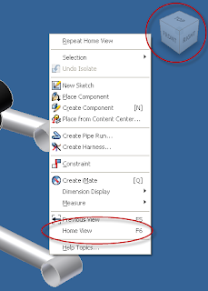
There is still away. Choose a new view using your View Cube, right click on the View Cube, and choose 'Set Current View as Home'.

You can select from two types of home views (From the Inventor Help on the topic).

  • Fixed Distance: Sets a Home view that defines both the direction of the view and the extent of the model that fills the view.
  • Fit to View: Sets a Home view that defines the direction of the view and the extent is always ‘view all’. The initial Home view of Legacy documents is set to Fit to View.
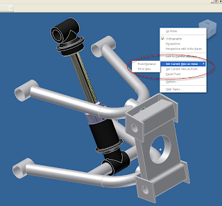


Now when you right click and choose the Home View. The that view will be redifined to what you want it to be.

A big difference between R2009 and its predecessors is the home view can be any view, not just isometrics like in earlier versions.

In KETIV news:

For those who are going to be at Autodesk University in Las Vegas starting December 2nd, look up the classes being held by two of my colleagues, Nicole Morris and Mike Carlson! I'm sure there's a lot of great information they can offer!

Mike's Class

Stop Stringing it! Digitally Prototype those Wires and Harnesses


Learn to use Inventor Routed Systems to Digitally Prototype your wires and cables. Stop using the "old school" method and add more value to your mechanical design. Time and money have been wasted on electrical design and now you can virtually eliminate that waste. No more issues with tight radius bends and rework of mechanical components to allow proper clearance of for cables. Learn how to communicate with AutoCAD Electrical using XML imports and exports. Finally, document those designs effectively for manufacturing with nailboards, run lists, and cut tables.


Nicole's Class

Unleash the Spreadsheet

Learn how to increase the power of AutoCAD Electical using spreadsheets. Automate, populate, and stimulate your drawings with software you already know how to use. Learn the ins and outs of creating data outsite and brining it into AutoCAD Electrical. See how many designers use spreadsheets to plan a project and reuse data effectively. Understand the fundamentals of these tools allowing you to cut production time in half.

Become comfortable with how spreadhseest are handled in AutoCAD Electical so that youc an create your own versions. Samples and Datasets included.

One last note. Happy Halloween!


Monday, October 13, 2008

Playing Your (Drawing) Scales

Just a short tip on one of those 'little' things that comes up from time to time.

I came across an issue where someone was placing an AutoCAD drawing in Inventor (via the cut and paste method), and the view pasted into the file was the wrong size.

Closer inspection showed that the view was scaled to a factor of 24.5. In other words, the part was created in mm, and had been pasted into an inch drawing (or vice versa).

In any case, here's a quick way to fix those when they come up.

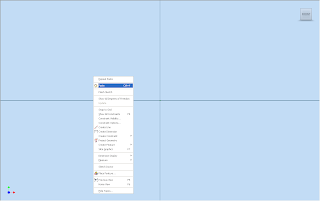
Once you've copied your geometry from AutoCAD, Paste it into Inventor as you normally would.


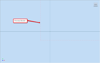
You'll see the preview box, however, before you left click to place the view, right click again.


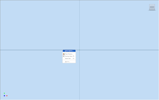
Right click and choose 'Paste Options'


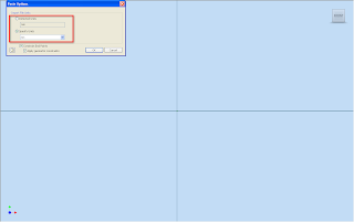
Once you choose Paste Options, you'll see the options screen that will let you specify what units the sketch should be in. Pick the units, and this should fix the issue!


Thanks again for coming to Autodesk Manufacturing Academy (AMA). Feel free to swing by our website here, and take a look at some pictures.

Wednesday, October 01, 2008

I Prefer Perfect Perforations (in Sheet Metal)

First of all, thanks to everyone who came to the Autodesk Manufacturing Academy. It was great to see some old friends, as well as meet some new ones!


Here's an interesting little problem a user ask us during the sheet metal class (I'm sorry but I dont' remember the name!).

How can perforations be created on a sheet metal part in such a way that the geometry can be cut on a CNC machine of some type (laser, water jet, etc).

One of the simplest solutions would be to create a transparent texture that would visually show the perforations, but that doesn't give you any geometry that could be cut by the machine.

Another method would be to try to model the perforations and use a pattern to wrap them aroudn the folded model, but that could be tricky, and if the pattern gets to be large, could cause a performance issue.

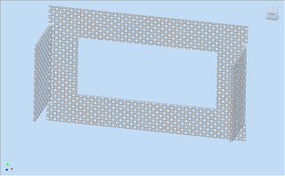
Another option a bit of a marriage between the two options. You can create a folded model without perforations, but add them to the flat pattern using the modeling tools there.

The perforations won't show in the model, but you'll have them in the flat where the CNC machine will cut them.

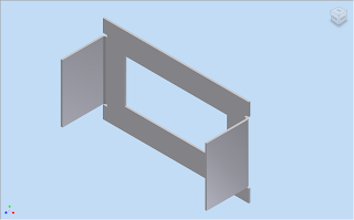
Here's the folded model.


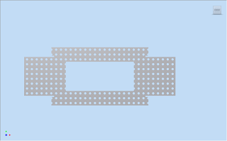
Here's the flat pattern, with some sample perforations added in the flat.


In this method, you achieve a balance between the need for and accurate part representation for the machine, while eliminating the extra effort of trying to maintain the pattern on the folded model!

And if you still want it, you can still use a texture for something representative on the folded model!