Find us on Google+ Inventor Tales: Random Warbird of the Weekend
Showing posts with label Random Warbird of the Weekend. Show all posts

Wednesday, January 11, 2023

Running Stress Simulations on a World War 2 Era Part


 I've been using Fusion 360 to model parts from World War 2 era parts It's a project I enjoy on the occasional evening and weekend. 

But some time ago, someone asked me, "Have you ever run a Stress Analysis Simulation on one of those parts?" 

It seemed like an interesting challenge. What would a part designed in the 1940s look like when tested with a modern Finite Element Analysis (FEA) tool. 

So I decided to fire up the Simulation module in Fusion 360, and set up a stress test to see how a component I'd modeled would hold up. 

The part I decided to use was for a P-51 Mustang, made by North American Aviation. 

The part itself is the body for a "Hydraulic Landing Gear Uplock Timing Valve". I decided I'd see how Fusion 360's simulation tools would analyze this old component. 


First, I set the material. The print listed the material as "24ST", which is a designation now obsolete. However the new equivalent is 2024. So I created that material in Fusion 360's material library, and applied it to the part. 

An excerpt from the print.
The 24ST aluminum bar can be seen in the material column

First, I needed to figure out what pressure I would be testing for. Based on the document I found here, the P-51 has a "low pressure 1000psi system". That comes out to about 69 bar in the metric system. 

For my test, I'll double that by applying a pressure of 2000 psi (138 bar). I'm using that as my burst pressure for this housing. 


As for fixing the part, I used the two mounting holes in the housing. 


With all that said and done, it was time to fire the simulation off into the cloud and wait for the results. 


All I can say that in the engineering parlance, I'd call this part "hella strong". Even at double the expected operating pressure, the minimum safety factor is about 4.5!

Assuming my analysis setup is good, the part is probably overbuilt and could be optimized to save weight. 

So why didn't the engineers at North American spend more time reducing weight? 

That I can only speculate on. 

But there are some things to consider. The body was created without the benefit of simulation tools. Add the fact North American Aviation was designing this aircraft in the middle of a war, one can probably see how not every part is optimized as much as it could be.

Add to that, the part measures about 3in x 1-1/8in x 1-5/16in (76mm x 29mm x 33mm), Even though weight is important in aircraft, optimizing this part probably wasn't a high priority considering it's small size. 

So there we have it! A P-51 Mustang part analyzed in Fusion 360. It was a fun exercise to see what stresses on this part would look like when analyzed on a modern tool!

Happy modeling! 

Jon

Acknowledgements:

P-51 Mustang print available from  AirCorps Library

P-51 Mustang picture takien at Planes of Fame Air Museum


Friday, September 02, 2016

Old Technology Flashback - The Boeing P-26 "Peashooter"

This Friday's post is just a video of old technology.  It's just a fun way to look back on how things were, "once upon a time".

Planes of Fame Air Museum in Chino, Ca. USA, has a restored, 1930s vintage, Boeing P-26A Peashooter

The P-26 outside its hanger at Planes of Fame  

It still starts in the same way it did in the 1930s when it was a front line fighter.

With an inertial starter.  You can find a brief blip on the technology at this Wikipedia link!

That means spinning up a flywheel, and using the flywheel to turn the engine and get that precious first spark!

But a mere description doesn't do the old technology justice.

Check out the video below!  Those guys had to be in incredible shape!

Tuesday, August 16, 2016

Lessons in Manufacturing from 75 Year Old Airplane.

Have you ever looked at a manufacturing process and thought, "When was that process developed?"

I had that moment looking at a set of ailerons for a Seversky AT-12 Guardsman at Planes of Fame Air Museum, where I volunteer on the weekends.

The Seversky AT-12 Guardsman at Planes of Fame
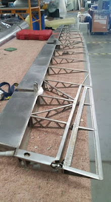
Stripped of the fabric that normally, covers them, I had a rare opportunity to see the structure beneath.

Typically Structures of the era would be made of wood, or riveted aluminum like the images below.

An example of  riveted aluminum. 

A typical aluminum control surface.
This is in the process of being recovered in fabric. 
Instead, these structures were made of welded stainless steel that had been spot welded together.

A close up of the stainless steel structure.  The spot welds are the dark spots on the ribs.
And speaking of the era, the ailerons still bore their manufacturer's data plates.  Built by Fleetwings, in 1940.


My curiosity piqued, I looked up the company on the internet.

I found that Fleetwings started in the mid 1920s, and pioneered the use of stainless steel in aircraft structures.

It seems that this set of ailerons represents a small milestone in manufacturing of aircraft structures. The use of stainless steel.

It's an interesting note in manufacturing history!  All prompted by looking at a set of old ailerons.


 With so many tools that we have, we can be better, faster, and more efficient.  But don't forget to use those tools to be come something else. 

Become more curious, and always keep learning! 

Friday, May 08, 2015

A Post for KETIV - Walking Through History at the Planes of Fame Airshow.


For those of you who know me, even if it's only via the Internet, it's no secret that I like vintage aircraft.  I find the stories about them fascinating, and the people who designed, built, flew,and maintained them fascinating too.

The Grumman F7F Tigercat in front.  Two Vought Corsairs in the background.

Last week, my bosses at KETIV Technologies asked me to write a blog post on the Planes of Fame airshow, and I found myself struggling with quite the case of writer's block.  So much to say, and how to say it.

Fortunately, I was able to put thoughts to virtual paper, and come up with something, and now it's been shared to the KETIV website.

So rather than repost it here, go ahead and follow the link to the KETIV blog here.

I hope you enjoy the article, and here's a couple of bonus pictures for passing through my blog on the way there! :) 

A Douglass C-47.  A loyal, dependable, workhorse of an airplane.

A Lockheed P-38 Lightning, of World War 2 fame, taxiing between two
North American P-51 Mustangs after a flight.

Later on, a F-22 Raptor flew.  State of the art today, here it is taxiing back
between the same two Mustangs.


Sunday, August 04, 2013

A Blog Delayed this Week.

I had high hopes for writing a post this week!  But I had to take a business trip to Minnesota, and due to a couple of delays, I got in just late enough to clean up and get to bed!

So look for a post a little later this week!

And to hold you over, here's a video of the Planes of Fame F4U Corsair starting and flying from this weekend.

Apologies for the shaky camera work.  It was the best I could do with my little point and shoot camera! 

Wednesday, May 01, 2013

A Quick Tour of the Pixlr Photo Editors Included in Autodesk 360

“the highest regard you can receive. That photo can describe an entire life, just an honor, as well as a fun moment.”
Aaron Eckhart

One of the things Autodesk Showcase can do is publish renderings both locally, and to the cloud via Autodesk 360.

Rendering an image both locally and to the cloud
But one of the things I recently learned, quite by accident, is that Autodesk 360 will do more than just store the renderings for safe keeping and sharing. 

It also contains tools from Autodesk Pixlr, which allow for additional photo editing to the image even after it's been rendered from Showcase.  So additional effects to make for a more eye-grabbing image can be created if desired. 

Before, I only knew this tools to be available for mobile devices, I hadn't realized they'd made their way to Autodesk 360 too!

These tools can be access by using the "Actions" pull down in Autodesk 360.   There the tools Pixlr Editor (Advanced) and Pixlr Express (Efficient) are located.

Below I'm using the scene I used from my previous blog post on the "Depth of Field" settings in Showcase 2014.


Choosing the editor
Selecting Pixlr Express, the editor will open and allow effects beyond what was created in Showcase available. 


The effects toolbar
The effects include things like:

Adjustment: Find tools like, Rotate, Blur, Resize, Rotate, etc. to images.
Effect: Tools to soften, age, make unicolor, etc. to images.
Overlay: Overlay effects like Flame, Fireworks, and more.
Border: Add several different borders to the image
Sticker: Several "stickers" are available to place on the image.

Below is an image in the process of having an effect added.


Editing the image.

When all is done, a new image with new effects is created and can be used.  So if there's a need to tweak an image, or just create something with a little more "artistic flair", the Pixlr tools on Autodesk 360 can be a nice way to add what's needed.

Below is the completed image, with an aging effect and a border added. 


And don't forget, there's also Pixlr Editor, which adds a lot more tools for even more photo editing options!

Pixlr Editor for more editing tools
 Below I've used it to to remove the truck in the background from another rendering created off the same scene.


Note the truck in the background on the left side.

I'm not much of a photo editor, so it's not difficult to see my edits.  Someone with a little more skill can do a much better job.

The truck hidden!  Even though the user's skills aren't very good!
 So there we are.  Some of those little known tools inside of Autodesk 360.  But if needed, they'll be there to add more punch to an image.

And on a final note, everything I've done has been using Autodesk Showcase, but any image can be edited.  So that means images created from an program, or even a photograph can be manipulated.

Below is an image I took in Lake Tahoe in Summer 2012.


And now one with a few effects added.


All that's left is for you to give it a try!


Sunday, April 28, 2013

Using the New "Depth of Field" Setting in Autodesk Showcase 2014

“There is only you and your camera. The limitations in your photography are in yourself, for what we see is what we are.”
Ernst Haas

One of the challenges in using Autodesk Showcase is getting the rendering, and particular, the focus of the rendering stand out.

Its one of the reasons that many times, I don't like putting the subject of a rendering "in it's natural environment".  It looks like it belongs there, and it just disappears.

But on the other hands, there are definitely times that there's a benefit to putting a subject where it belongs, in a shop, in a lab, or on a street, for example, instead of in an "empty photo room".

One of the new tools added to Autodesk Showcase 2014 is the "Depth of Field" setting, which, like the F-Stop on a camera, controls how the scene is focus, and how objects "blur away" as they get further from the "lens" in the scene.

In the scene I'm using here, I've taken a picture of the Planes of Fame B-25 Mitchell, created a backdrop, and inserted two engines, which are models I downloaded from GrabCAD at the link here. 

I'm not using any depth of field settings.  I'm just using the backdrop "as is".

The two engines place in the scene with the B-25

Everything is in focus.  And while it might be easy to look at the engines in the foreground, it's also possible that the person viewing the image might not be immediately drawn to the engines

With the Depth of Field setting, the background can be blurred and the focus of the scene can quickly be places on the engine.  So how does depth of field work?

I start by going to View>Camera Properties.

Choosing Camera properties.

Once the Camera Properties come up, click "Show More Controls" under lens effects.  "Depth of Field" will appear there, check the box to enable it.

Choosing depth of field.

Now, I can select "Click on Object", and choose the engine closest to the foreground on my screen.  This tells  Showcase where I'm "aiming the camera".

Choosing the object of focus
Once this is done the sliders for Focal Distance and F-Stop can be used to change the focus of the scene, and bring one object into focus, and blurring the others to bring out the desired effect.


Changing the Depth of Field settings

Once the desired effect is achieved, select OK to accept the new result!

The completed result

So go ahead and give these settings a try.  Like so many settings in Showcase, there's not a right or wrong way, just what you like!

And for the steps in a video form, look below!


Sunday, April 21, 2013

Enhance Your Presentations in Autodesk Inventor - A Guest Video

“One should strive to improve one's capabilities. One should enhance his abilities only in the positive direction. ”
Rig Veda


This weekend was a busy weekend as I tried to get some personal errands wrapped up, as well as spending my usual Saturday at Planes of Fame working on fabric control surfaces, and watching the first arrivals for the big airshow on May 4th and 5th.

An aileron for the D4Y Suisei (allied code name "Judy") in the process of restoration

Warbirds gathering for the airshow.  From front to back a T-6/SNJ Texan, a Douglass AD Skyradier, a Vought F4U Corsair, a Northrop N9MB Flying Wing, a Douglass SBD Dauntless, and way back, a Douglass C-47 can be seen.

Nonetheless, I ran out a time to put together a quality blog post, so I'll be creating one a little later this week.  But in the mean time, check out the Tech Tip created by Bill Bogan, fellow compatriot at KETIV Technologies.  He shows us some tricks that can be created with presentation files!


Sunday, February 10, 2013

Increasing Shaded View Resolution in Autodesk Inventor

“If a window of opportunity appears, don't pull down the shade.”
Tom Peters

This week is a short tip, due to some required domestic repairs around the house.  A gate pulled out its hinges, so a big part of my blog time was spent fixing that.


Time to get busy!

All that's left is the painting!
Fortunately the gate is repaired, except for a little paint, and there's still some time left for blogging!

So here we go!

 One tip that I've always thought was helpful was how to set Autodesk Inventor's drawing settings to get the crispest shaded view possible.  It's one of those settings I usually check right away.


Sometimes, when zooming in closely on a shaded view, the colors appear blurry.  It's almost like water colors were used to create an artistic effect.   In this example using the section view of a bicycle fork, the colors can even run into each other, making it more difficult to see the components clearly.

The bicycle fork used in this exercise.


The colors bleeding together on the drawing.  It would be nice to clear these up.
Fortunately, this isn't a difficult setting to change.

First, find the "Tools" tab, and choose "Document Settings".

Finding Document Settings
On the Document Settings dialog box, choose the "Drawing" tab.  On this tab will be a section simply called "Shaded Views".  Change the "Use Bitmap" option from "Always", to "Offline Only.

Changing the setting.
 Click okay, and check out the section view.  Much better!

A crisper looking shaded view

There is one more tip, however!  If you want this setting to be used in all future drawings, check the drawing templates and make sure the setting is changed there!  This will make sure any new drawing is using the desired shaded view setting!

And of course there has to be a video to go with it!  So below you'll find the video version of the tip. 


And one more video, purely for fun!  Here's a video of the Planes of Fame F-86 Sabre and Mig-15 flying formation at the Living History Event on February 2nd.  The camera perspective is really cool!  I thought it was really interesting to see the leading edge slats on the F-86 working!


Friday, September 21, 2012

Off Topic - The Space Shuttle Endeavour

“What is history? An echo of the past in the future; a reflex from the future on the past”
Victor Hugo

It can definitely be said that this post is off topic.  I didn't use Autodesk Inventor, Autodesk Showcase, or anything for this blog.

All I had was the opportunity to see the Space Shuttle Endeavour make her last flight to her final home, The California Science Center.

I couldn't resist.  This would be the last time that I could see a space shuttle in the air, even if it was riding piggy back on a Boeing 747.

A few of us from the office headed a few miles down the road to Anaheim, and saw the 747 carrying Endeavour on it's fly by of Disneyland.

It was impressive on so many levels.  The engineering feat of the 747 carrying Endeavour, the excitement being able to watch history being written. 

And last but not least, a little bit of sadness knowing that this is the end of an era.

So hear are my pictures of "Endeavour's Last Ride".  I hope you enjoy them as much as I did! 

At first it looked like a ghost in the Southern California haze.
But it was very real indeed!

You could feel the excitement in the air.

It was amazing to see it get closer.

And just keep getting bigger.

And bigger!

And become a truly impressive sight!

The chase planes look tiny!

A grand entrance for Endeavour

And she heads away

Her flyby is over.

And a grand space craft heads for her final home.