Find us on Google+ Inventor Tales: Inventor Assembly Topics
Showing posts with label Inventor Assembly Topics. Show all posts

Tuesday, June 07, 2022

My Tool Won't Fit! A Design Lesson From Life.

A typical aircraft brake disk.
There's not much room for a socket!
Hands on experience is often the greatest teacher. 

And, while helping work on a friend's change tires on a light aircraft. 

In looking at the brake disk, bolted to the tire rim, I saw that there was no way one could get a socket, the ideal tool for the job, onto the bolt. 

Fortunately, my friend, having run into this case many times before, had a wrench he'd cut to fit inside the disk. So in the end, it was job that was still very easily accomplished. 

But there lies a lesson for those of who sit behind a desk and design the machines we use every day. 

Just because the fastener fits, doesn't mean the tool will! So when designing, think of ease of maintenance. 

The maintainers, who are sometimes your customers, will thank you for it! 

About the Author:

Jonathan Landeros is a degreed Mechanical Engineer and certified Aircraft Maintenance Techncian. He designs in Autodesk Inventor at work, and Autodesk Fusion 360 for home projects. 

For fun he cycles, snowboards, and turns wrenches on aircraft. 

Sunday, September 11, 2016

Constraining Content Center Components in Autodesk Inventor - An Alternate Way

Recently, I've been doing a lot of work with content center lately.  I've been building content, publishing content, and fixing content.

It can be tedious, but it can also be a lot of fun.

But there's one trick I've picked up in my travels.  It's how to constrain content, in particular custom content, a little more quickly than by using the standard method.

Now before I get started, one disclaimer.  I'm using standard content to demo my blog, I didn't have customer content center fasteners I could share with you, so I had to borrow the standard.

Since I'm using standard content, I also I know I could use Autodrop, but the point was to show an alternative.  All I ask is you bear with me on the standard content part.

So with that said, it's time to get started.

Of course you'll need to place your content from the browser.

Selecting content to place

2) When the fastener previews, right click and choose the size you want to place.

Choosing the size of your content center fastener

3) Next left click to place your fastener, but here's the trick.  Without you even knowing it, the insert constrain is active.  Before you left click to place the next fastener, left click under the head of the fastener you wan to place.

Selecting under the head of the fastener
4) Now select the mating hole, the insert constraint will be created!

Completing the constraint with a second click on the mating hole
5) All that's left is to repeat the steps if you have multiple fasteners!  You don't have to exit the command!

Repeating the step for multiple fasteners. 
So give it a try if you have content you're using, particularly custom content.  I've found it helps me out, I hope it does the same for you!


Sunday, December 06, 2015

Why is Inventor Constantly Freezing?!? - Wait, it's not Inventor's Fault!

Earlier, this month, I relived. something many CAD users have experienced.

Frequent freezing and crashing!  The bane of any CAD jockey!

When a CAD system crashes, this is what designing feels like.
Let's paint a picture!

A natural first reaction is to blame the CAD system, then perhaps the hardware.  Next may come the universe and any crimes you may have committed in a past life that have resulted in such Karmic retribution.

But there was one thing that blew everyone of those theories out of the water.  Well, except for the Karmic retribution theory.

Inventor hadn't been having this problems before.  It had been rock solid in the days, even hours.

So I traced back to what I was doing when the freezing and crashing started.  What had I done?

It turned out, I had imported a step file that represented a gearbox. A coworker confirmed that he'd experienced the same thing on his system with that same model.

Smoking gun located!

This was my culprit.  You evil, evil model. 


Confirming the Symptoms

Opening and inspecting the gearbox by itself, There were a few symptoms the model exhibited that indicated it as our sick file.  One of them may not be a problem, but together, things start to click.

1) The size was larger than I expected.  It was about 5MB.
2) The file took forever to perform even simple operations.  Things like placing constraints in an assembly, or creating a sketch in a part took several minutes to calculate.
3) Then aforementioned locking up and crashing.

At this point, I was sure I had found my culprit.

The Solution

I recalled a discussion with a colleague many years ago, I remembered a corrupt step file that had caused crashing in her system.

In that case, there was a weird, intersecting face that crashed the system.  The solution there had been to locate it and cut it away.

I actually tried that, but after about an hour, I hadn't located the problem.  I even tried loading the file into Fusion 360, and still ran into performance issues.

It was time for a different approach, which I should have tried in the first place, in retrospect.

I downloaded a new model!  But instead of a STEP file, I tried an SAT file.

And that worked!  The system was stable again.  It didn't crash again after that.  The file was less than 1.5 MB,

It feels good to be under way again!


The Conclusions

Bad or corrupt neutral files exist.  They're unavoidable.  Like a game of telephone, they can be caused by bad translation, bad imports, or sometimes, just bad luck. I couldn't tell you the cause of this models issue, and ultimately,, my superiors didn't care.

They wanted the project moving, they didn't care about which corner of the model had an issue.

I encourage you to be aware that "bad models exist!"

Some CAD models just fall in with the wrong crowd....


Moreover, when your program of choice begins crashing, remember that crashes aren't always the fault of the program.  Whether your using Inventor, Solidworks, Solidedge, or "My-CAD-Program-is the-best-and-if-you-disagree-your-wrong" CAD (We all know who those guys are!), look at what you did just before the crashing started.

It's always possible that whatever that was, a model, a bad constraint, sketch, whatever, is your "bad seed"

Keep your eyes open!


Photo Credits

photo credit: image29991 via photopin (license)

photo credit: L'hydrofoil via photopin (license)

photo credit: 45/52 Cat Burglar via photopin (license)

Sunday, November 01, 2015

Show Sick Constraints in Autodesk Inventor - A Newer Trick That's Worth It!

To borrow a phrase from Fiddler on the Roof, "Our old ways were once new, weren't they?"

And I'm reacquainting myself with building, changing, and modifying assemblies in my new capacity.  That means changing geometry after parts have been assembled.

And that means dealing with sick constraints!

They say an ounce of prevention is worth a pound of cure.
But sometimes you need a heaping pile of cure.
I had to change a hole into a slot in order to give a part a easier to adjust.

Note! For this post, the top nut and washer have their visibility turned off to make the slot easier to see.  But it is there!

One of these holes has to become a slot
Creating the slot is easy enough.
However there were threaded rods and nuts that were constrained to the now removed holes, and naturally, those constraints lost association.

Locating these in the browser is usually easy enough.

The sick constraints in the browser.


But then I remembered that there's a tool that will make glyphs visible on screen to show me where my problem constraints were.

It's called Show Sick Constraints, and it was actually introduced in Inventor 2014.

Clicking this tool shows glyphs for the sick constraints right in the modeling window.  By right clicking on these, the options to change the constraints become available

The glyphs shown.  Note one washer/nut combination is invisible
Choosing the Edit option, the lost constraint becomes visible.  It's represented by the red arrow.

Right click on Edit


By clicking it, I can re-associate the missing constraint to the new geometry represented by the slot. It's just like when the constraint was added in the first place.

Replacing the constraint.  The nut and washer are invisible.
This makes it easier to select the desired geometry.

When compared to fixing constraints by the "right click in the browser" method, I found this to go by quickly.  I wasn't checking the browser, and using tools like "Isolate Components and "Find in Browser" nearly as often.  And while those are great tools, "Showing Sick" made the process smoother with a minimal amount of "mouse mileage".


The constraints restored!  The glyphs can now be hidden if desired with
the "Hide All" tool net to "Show Sick"
It's a nice tool that helped me quite a bit in this particular situation, I'd suggest you take a look and add it to your repertoire of tools!

Photo Credits

photo credit: photo credit: Conefluence! via photopin (license)

Tuesday, March 24, 2015

A Case for Using Adaptivity in Autodesk Inventor

Back when I started working with Inventor, Adaptivity was all the rage.  It was shown in every training class, seminar, and demo I ever attended.

But as new tools come out, old ones fade into memory.  But just because a tool has some mileage on it, it doesn't mean that it's become less useful.

And so, I go back in time to revisit adaptivity, and more importantly, a case where adaptivity was exactly the tool that I needed, when I needed it.

What is adaptivity?

This is what the Autodesk Help system states, at least in part:  "Adaptive parts and geometry have under-constrained features, and adjust to design changes."

In other words, an adaptive components are "squishy", and have flexibility to change based on the changes in other geometry.

A more compelling question for those using Inventor in their trade is "Where would I use adaptivity?"

Here, the Autodesk help system sums things up nicely.

In general, use an adaptive model:

  • When an assembly design that is not fully defined requires a part or subassembly in a particular position, but you do not know its final size.
  • When the position or size of a feature depends upon the position or size of a feature on another part in the assembly.
Drawing from the second bullet, I decided to share a case where adaptivity proved very useful to me, in hopes that it can give you some food for thought when you sit down at your Inventor station and hit that power button to start your day. 

The case I have is for a wood shop project I designed a few years ago now.  

The project is a blanket chest that I modeled in Inventor a few years ago,  

The blanket chest


Part of that design includes a design feature, sometimes referred to as a "cloudlift" at the base of the part that can be cut using a jig to guide the router cutting them. 

Isolating the part with the cloudlift. 

And that's the challenge, how could the shape be quickly transferred from the part being made, to the tool making it?  Sure, we could use the measure tool to and start transferring lines and arcs, but that's not efficient at all. 

So here's a solution!  I've built the jig to accommodate the part, all it needs is the cutout for the router to follow.


Now it's time to create the mating cutout.  First, edit the jig base and create a sketch where it's needed.

The new sketch is ready to go! 
Before projecting, here's a suggestion to make sure you're picking the correct edges,  Go to the view tab, and expand out the Appearance panel on the View ribbon.  Turn of transparency so the components that aren't currently being edited are solid.  It will make them easier to see in this case.

Editing the part with transparency turned off.

Now that we can see what we're doing, just use the Project Geometry to project the profile from the cloudlift on the part onto the jig.  

The sketch and part become adaptive by default.  

Projecting the geometry from the profile.
Note the adaptivity symbol in the browser. 

Now one more step.  In order to make sure the profile is closed, connect the open ends of the profile with a line.  


Once the loop is closed, extrude just like any other sketch. 


And now the jig contains exact profile from the part it's making!

But why go through this trouble?  What's the benefit/

For this application, the benefit is pretty simple.  If the cloudlift changes in size, the jig making it can change without the user having to make sure to size the mating part again.  And that can be a time saver if the part is in a fluid sate of design. 

First, the size of the driving part, the cloudlift profile is created.

The part sizes are changed.


After finishing the edit, the jig, being adaptive, will match the size without user interaction! 

After finishing the edit the jig resizes.

So there we are, all done!  A case where adaptivity was the perfect tool for the job.

But before you Inventor power users light up the comment section, I'll speak to the fact that you don't get something for nothing.  

There is a price to be paid for using adaptivity.


  1. It will drive calculation times up.  Every time you update an assembly where adaptivity may be changing, Inventor is going to check to see if the adaptive parts need to update.  You may not notice it at first, but as the assembly gets larger and/or more adaptivity is used, performance can get seriously impacted. 
  2. Parts can update without user interaction.  That's right, one of adaptivity's biggest strengths can be its biggest drawback.  A part can update automatically.  Sometimes updating in such a way that it no longer functions.  If it happens without you realizing it, then you have a big problem. 
    1. As a result, it's a common practice to turn off adaptivity once the design begins to solidify.   Right click on the component in the browser and uncheck "Adaptive". The part won't update automatically until you turn it back on. 
Turning off adaptivity.
In conclusion, Adaptivity can be a tool that can be extremely useful, but like any tool, one needs to know how, and where to use it.  While it's not the solution for every situation, when properly used, it can be a fantastic way to augment your designs. 

I'm afraid there's no video this time around!  I've been in a big time crunch the last couple of weeks, but I'm hoping to add in the next couple of weeks!  


Friday, February 06, 2015

Shimming Your Knowledge. Using the Assembly BOM to quickly change Properties


Every Autodesk Inventor part and assembly contain valuable properties, called iProperties by the Inventor folks.  A savvy user can place critical information into iProperties.  These properties are passed from the part, into the assembly, and ultimately into the drawing.".

This information can be critical to making sure your finished product comes together properly.

I would be the first to tell you that, in a perfect world, any Inventor iProperties you need filled out should be filled out before you place the part in the assembly.  You should also set the material as well.


But I also admit that the phrase "Perfect World" comes with an asterisk and small print that reads. "You don't live in a perfect world".

With that being said, do I diligently set my iProperties and materials at the part, long before I place it in an assembly?

That's a big fat NOOOO!

This is usually what I've done.  The assembly has been created,
but the descriptions and materials haven't been set

That's right.  I'm as guilty as anyone out there.  I may even be more guilty.  That's me, sticking it to the man, breaking the rules.

I'll fill out those properties whenever I darn well please Muhahahaha! 

Why don't I take my own advise?  Part of it is bad habit.  I always want to jump into building the models. The fun part.  Documentation?  That's just as important, but it's also boring.

Is it a good excuse?  No.  It's just part of a bad habit I haven't quite shaken yet.

That leaves me with the self inflicted challenge of having to go back and return to my models at a later date, often when they're nearly finished, to add in the properties and set the materials I need.  That task is at best tedious.  At worst, it's time consuming and painful.

But fortunately, I know a nice tool that allows me to change my properties and materials from the assembly, in one convenient dialog box.

The result is like you opened each part and subassembly individually and made these changes, but you don't actually have to do that!

Who needs a perfect world!

The tool of which I speak is the assembly Bill of Materials, which can be found on the Management tab in the assembly.

Accessing the BOM Manager.
The Bill of Materials  icon is grayed out because the BOM
Manger is already open.
Expanding the assembly in the Bill of Materials manager, the fields available to be modified appear next to their components.

But what if you don't see the components you want?

To add columns, select the Choose Columns icon and drag the field you want and place it in the title bar.

Adding a column using the "Choose Columns" tool. 

To remove a column drag it from the title bar to the middle of the screen.  Release the mouse when the "X" appears.

Removing a column from the BOM manager. 

You can add or remove however many columns you need.

Now with the columns you want configured, now you can start filling out your iProperties, as well as selecting what materials you want for your components.

That's more like it! 

This is definitely a tool worth taking a look at, if you spend a lot of time editing properties and changing materials, this should be a big part of your toolkit!

I know there's some of you that prefer video tips!  If you do, I've created another video for the YouTube channel here!

Friday, December 05, 2014

Five Quick Tips for Autodesk Inventor Assemblies

Avengers Assemble!
Marvel Comics

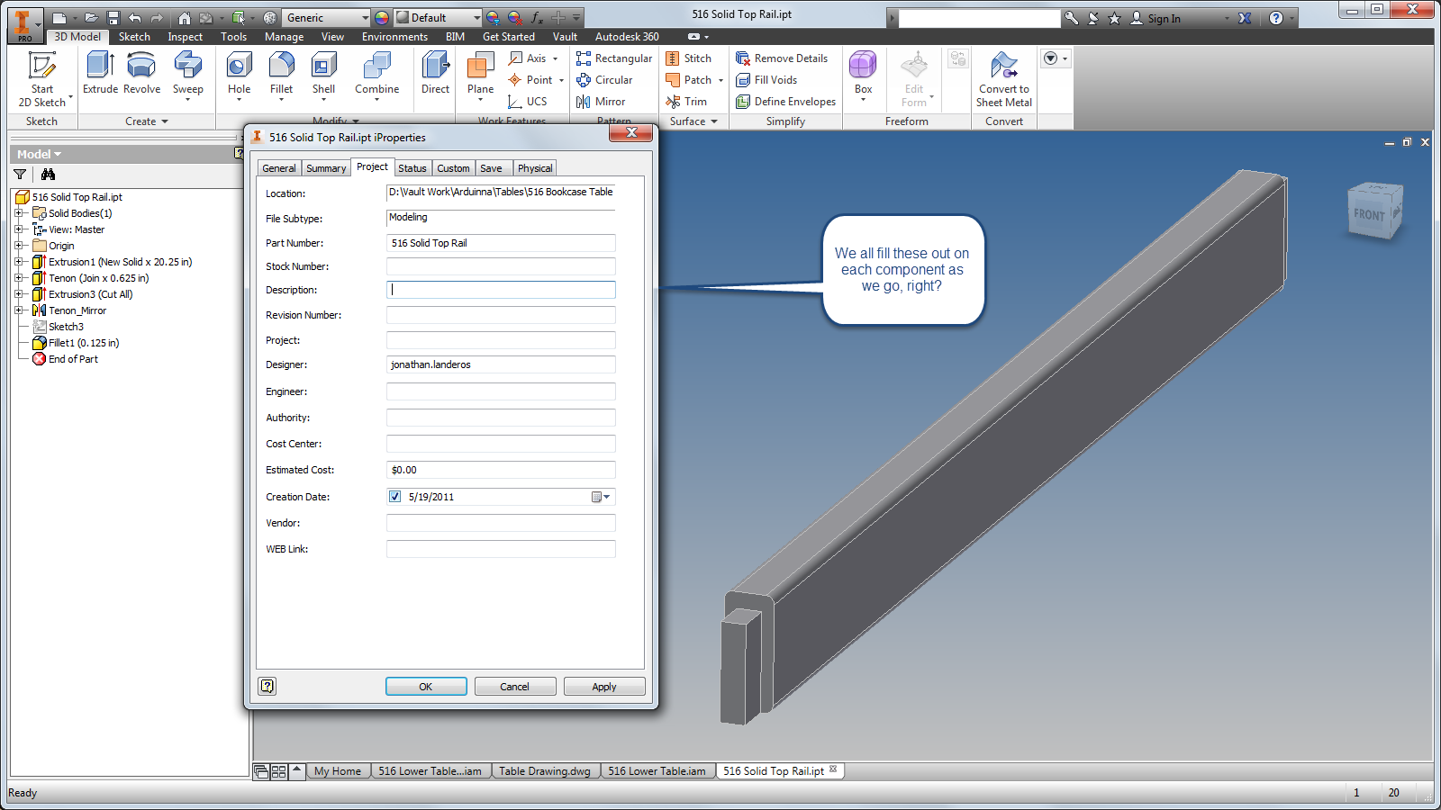
Over the course of the last few months, I've created tips of things that I thought others might find useful.  So far, I've created one for sketching, and part features  Now for the next step in the series, five Autodesk Inventor Assembly tips.

I've stated it in my previous tips, but I'll say it again.  These aren't in an order, of preference, just the order I jotted them down in.  Take the ones you like, and use them in any way you like!

1) Granted, this a bit of a repeat from part modeling, but this tip works well assemblies as well.  And that's the "Select Other" tool.

When assembling components, Inventor allows us to rotate components while adding constraints, I use this all the time, especially with my 3DConnexion device.

However, there are plenty of times that I don't want to rotate the parts when adding constraints, and this is where select other can come in real handy.


2) Other times when adding constraints, I need to place a lot of constraints quickly.  This is particularly true of insert constraints.

Inventor has another way of placing constraints that has been around as long as I can remember, but seems to have been lost over time.

That method is the Alt+Drag method.

In short, select the geometry to be constrained while pressing the "Alt" key, and the appropriate constraint can be selected.  Drag the constraint to the mating part, release the Alt key, and the constraint is placed.  All done without touching the constraint icon.

The act of using Alt+Drag

It's not a big time saver for a few constraints, but when placing several, it starts to add up.

There's more information from my earlier blog post here! 

3) Another tip I picked up over the last few years came from users who worked with a lot of sheet metal.  It's a creative use of the Flush constraint.

When selecting a small edge to be mated to another, it can be difficult to get the desired face.  Mate, being as flexible as it is, can start picking edges and points near the edge of the face.  It makes it tricky to get what you want.

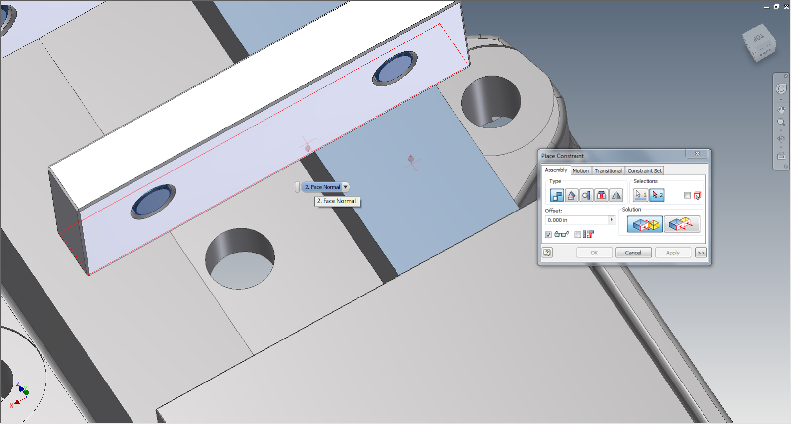
One option is to use the Select Other tool, just like I mentioned in Step 1, but there's another approach that I think might help everyone out.

That approach is the Flush constraint only see faces.  Starting with that as a constraint, will easily pick the face.  All that is left to do is switch it to Mate once the face is selected.

This can be a huge time, and patience!


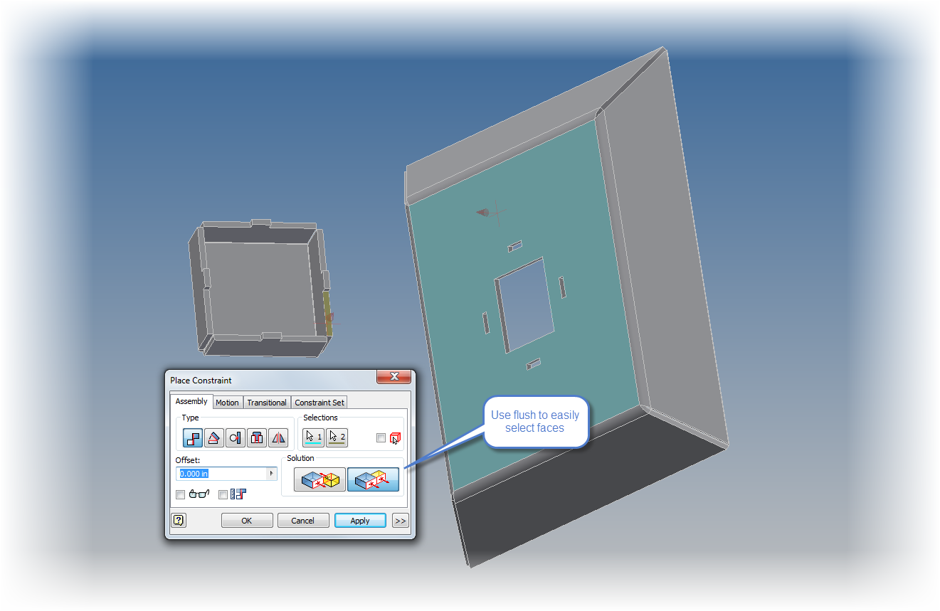
Here's a tip on using a flush constraint to pick a narrow face

4) This one has happened to me more times than I want to admit. I've started out with two parts that I swear are totally identical.  I have those components constrained into place, and everything is just about set....

Then I realize that there's one feature that makes one instance of the part different from the other...

Classic.  Two parts I thought were the same, and I realize they're not when they're already placed.

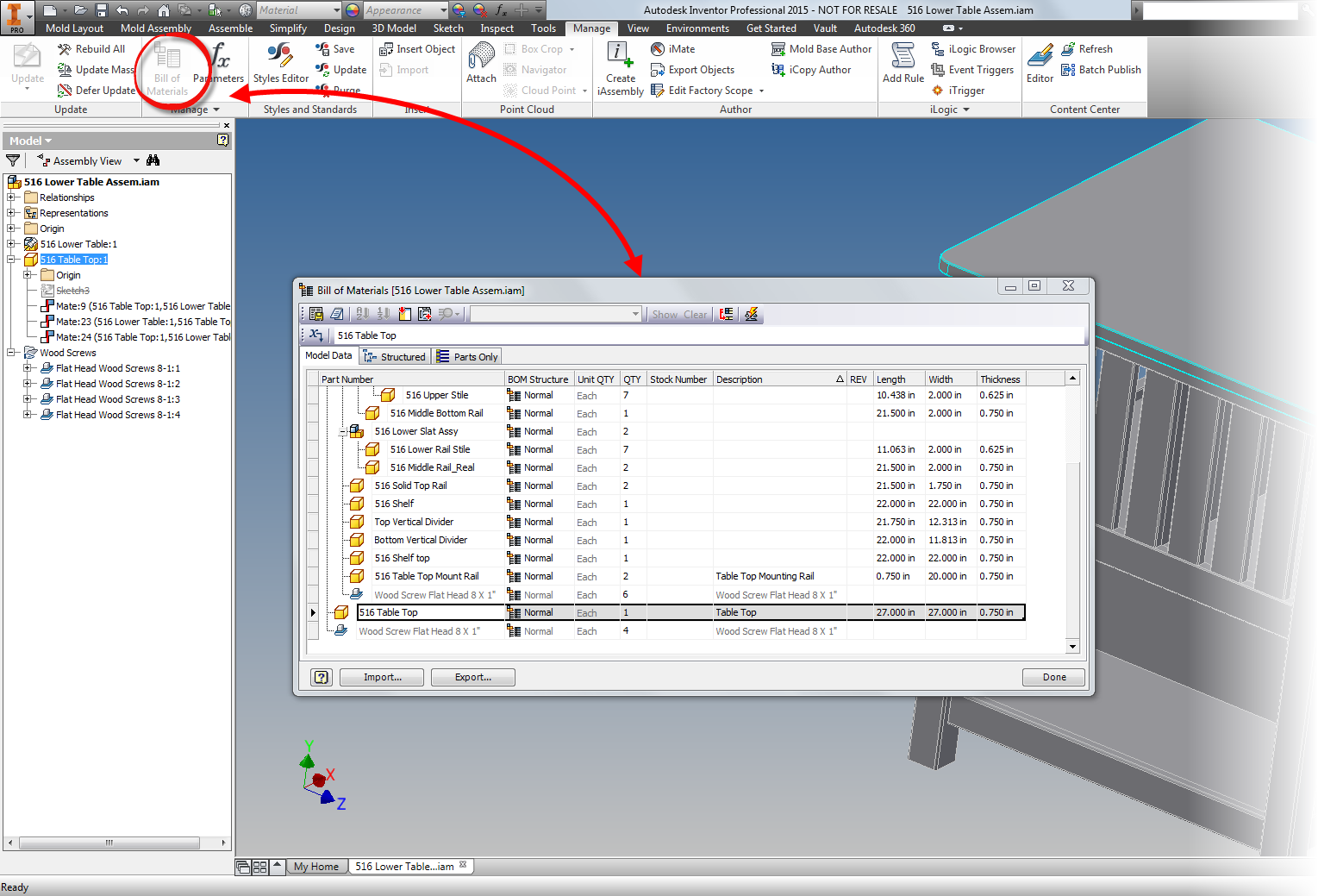
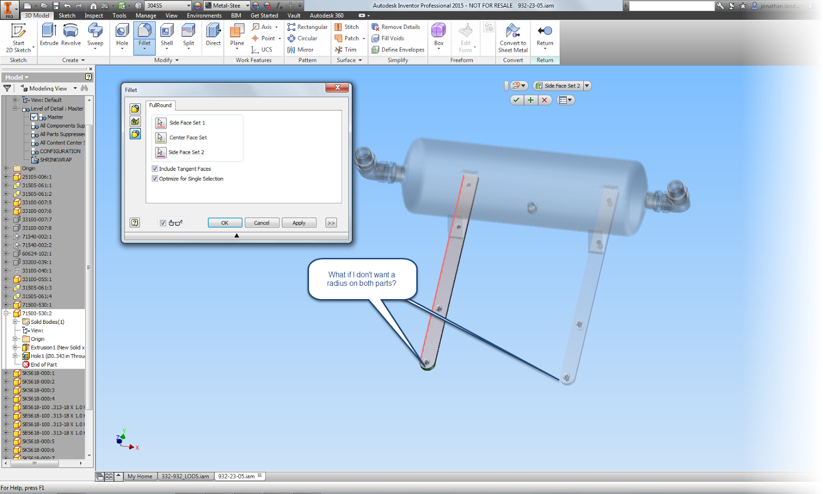
Fortunately, there's a tool called Save and Replace Component.  It's located on the Productivity flyout, and it's perfect for exactly this situation.

Locating the Save and Replace Component tool.
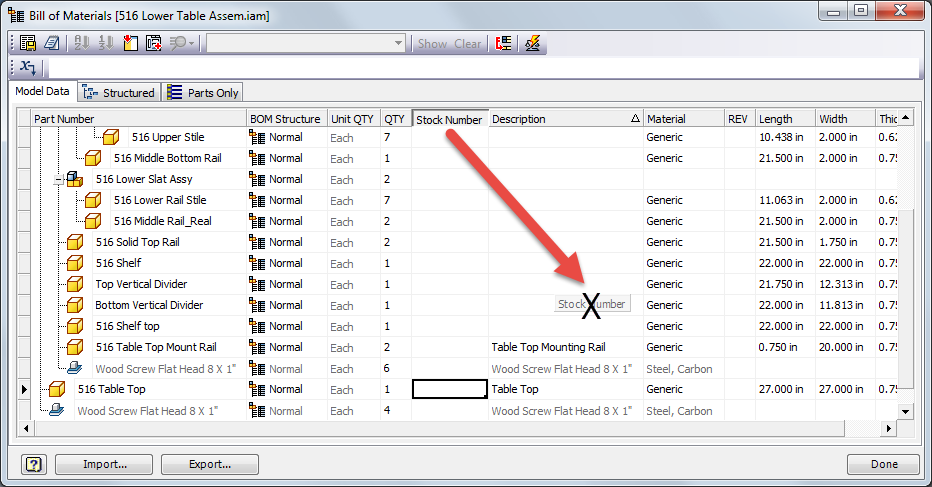
Save and Replace Component creates a brand new copy of the existing part, and swaps the new part for the old.

The bonus?  No constraints are lost, and you can quickly make the changes that make the part unique!

The result with very little inconvenience! 


5) Finishing up the assembly tips, one last one is a tip for a set of features introduced in Inventor 2014, but might have gotten lost in the forest that's created by so many new features.

It's not available in 2013 or earlier, so sorry for those on the older versions.

All of these sets are from the same group, so I'm combining them in together as a "super tip".

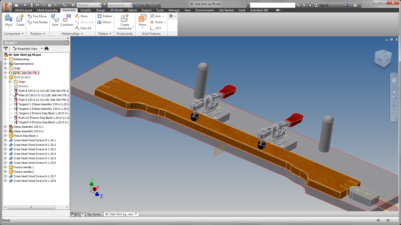
First, is to drag a part using the Free Move command.

In previous releases, this just moved the part away from the assembly, regardless of constraints.  But now it shows "bands" between the moved part, and the components it's constrained to.  It's a visual map to how the constraints are behaving. This also includes glyphs showing you what type of constraints are in use.  Right clicking on the glyphs lets you edit, modify, modify, and delete constraints.

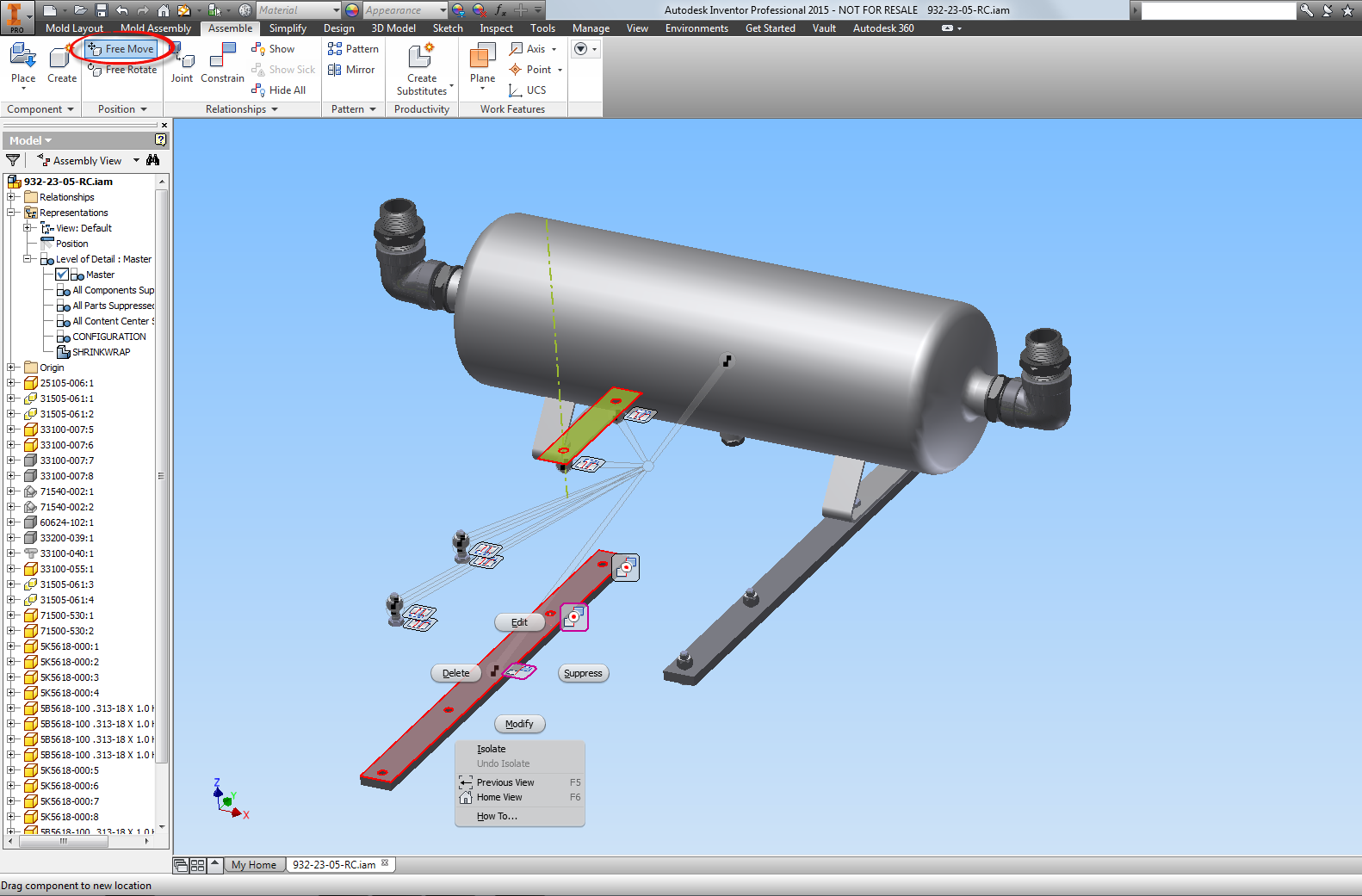
Using the Free Move command to show constraint relationships

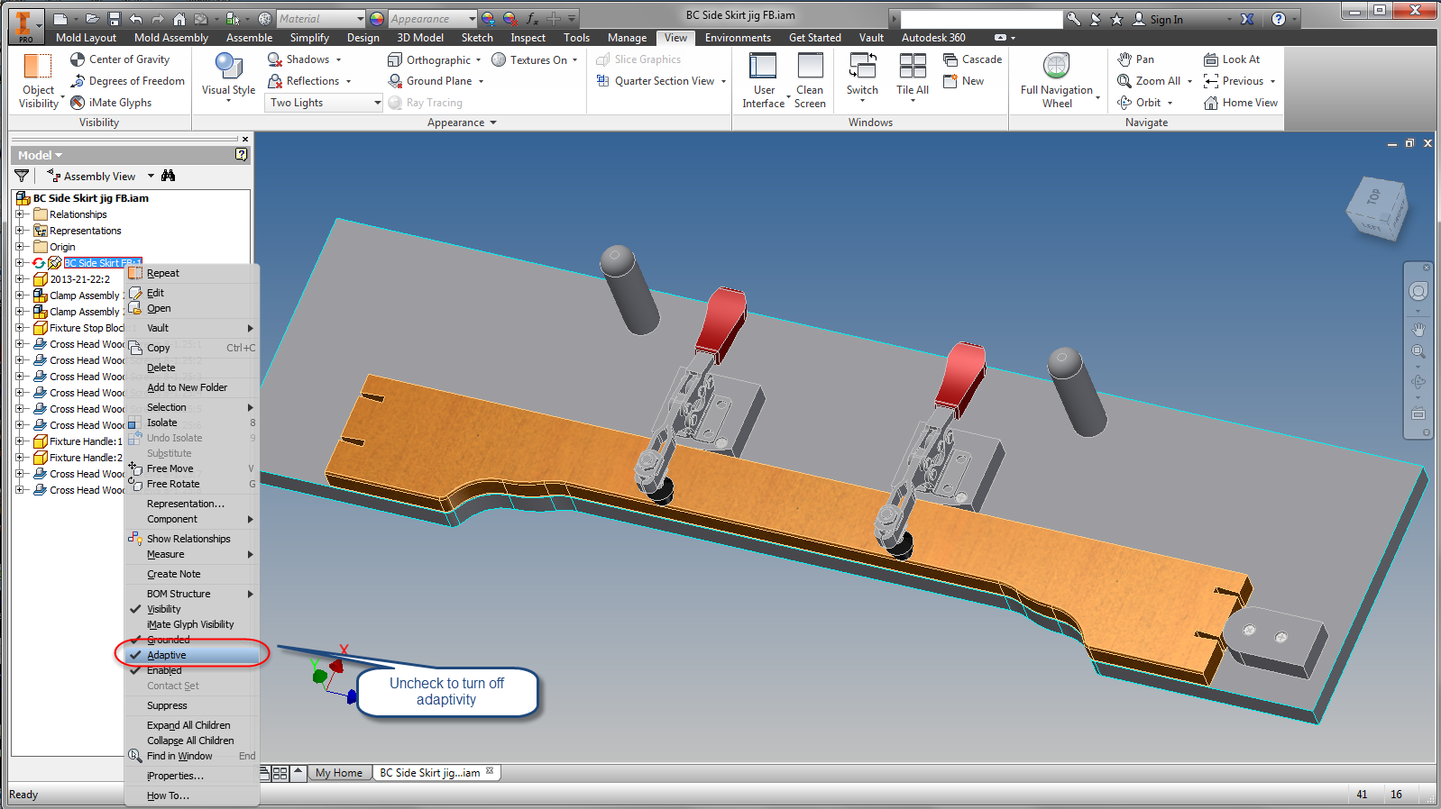
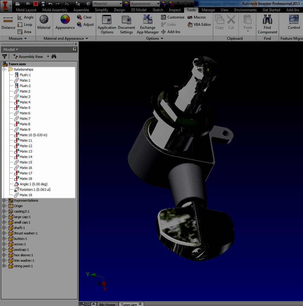
The other tools are on the 
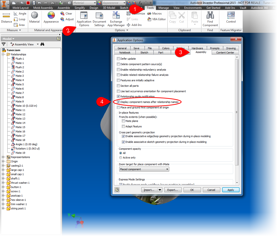
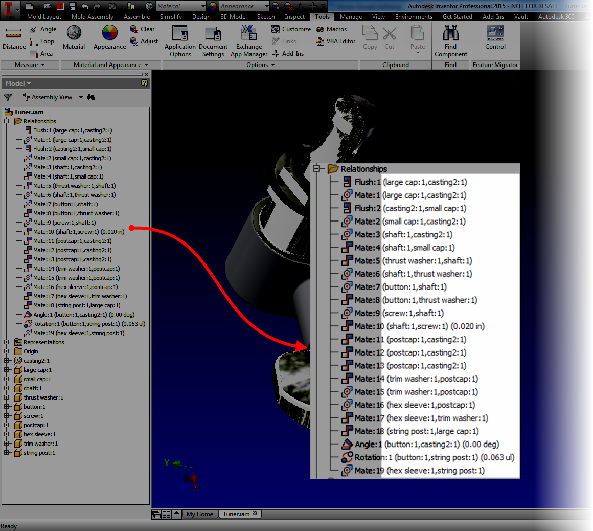
Relationships tab.  They're Show constraints, Show Sick constraints, and Hide All constraints.  The name says it all.

Show constraints displays the constraint glyphs for a component that you select.

Showing Constraint Glyphs

Show Sick constraints will show constraints that have conflicts with other constraints.\

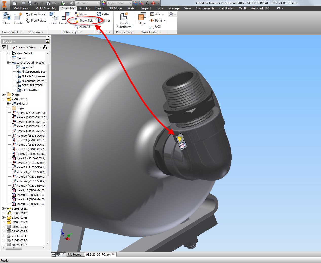
Showing Sick Constraints


Hide All constraints turns off all the glyphs.

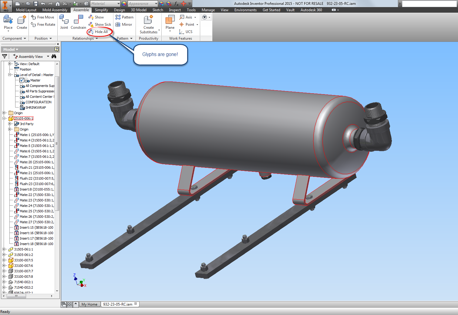
Hiding All Constraints


I know I've grown to like these tools as I've used them, but it can be easy to overlook them.

So if you've been upgrading and forgot about these tools, take a look!

And I know.  There isn't a video for this one.  Things have kept me rolling where I haven't quite been able to create videos.  I'm hoping that things might just wind down enough where I hope to create one soon!

****Edit 31-December-2014****

At long last, I had the time to create a video to accompany this post!  Take a look!  I hope you find it helpful!

And Happy 2015!


Sunday, July 27, 2014

Showing Component Names After Constraints in Autodesk Inventor! - A Nice Little Trick!

“Hey! I know you. Ask me your name!”
 Matthew McConaughey

As many have guessed, I love a simple but effective solution.  In my post last week, I discussed showing extended file names in Autodesk Inventor's feature browser.

Extended names shown in a part. 
In assemblies, there's a similar functionality inside of assembly files, but here it applies to adding more information to assembly constraints.

This option will show which components a constraint is acted on, right next to the constraint!

But why talk about it, when a few simple screen captures can show it all!  Let's see how to turn that function on.

I'm going to start with a baseline.  Expanding the Relationships folder, the default behavior can be seen.  The type of constraint, and offset can be seen..

An example of an assembly with constraints in their "as installed" state
I'm going to add the component names to the end of the relationships.  This setting is located in Tools>Application Options.

On the Assembly tab, make sure the "Display component name after relationship names" option is checked.


Once this option is checked, click OK to close the dialog box.  Now take a look!  The component names are displayed after the constraints.

Now, I can see component names behind the constraints

Now, there's an another option to viewing components behind constraints!  So take a look at this setting and see how it can work for you!