Find us on Google+ March 2020 ~ Inventor Tales

Saturday, March 28, 2020

A Challenging Channel - Modeling a Sheet Metal Channel in Fusion 360

On a morning this weekend, while hanging out at home with my coffee in my hand, I decided to play with Fusion 360.  I had a part picked out that looked simple enough.

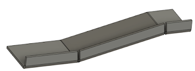
The finished part. It looks simple, but it hides a suprise

The part I chose looked to be a simple sheet metal part.  It looked to be a simple enough part, but it did have a joggle in it that complicates things a bit.

The joggle that changed how this part was made
Since it's got this joggle, it can't be easily modeled using sheet metal tools.

The sheet metal version wasn't quite what I was after.
So I decided to model it using the "regular" modeling tools.

I also decided I'd document how I did it here, for both posterity's sake, and in the hopes that it might give another struggling user an idea.  I won't go through every single step, but I will give an overview that hopefully encompasses the high points.

The first thing I did was model the envelope.  I nothing more than an extruded rectangle.  A "brick".

The starting point. An extruded rectangle representing the parts outer dimensions.

Next came the process of carving out the shape. I started with the joggle.

The joggles cut into the part. I've turned one of the sketches on to make it more visible.


Once the joggle was in, it was a matter of adding the remaining features, including the outside fillets that represent the outer bend radius.  Notice that the part is still a brick.  It's just a brick with some nice looking features!

The brick has all the features of the sheet metal part now.
This is where my original plan went wrong. My plan was to use the shell command to create the inner profile.

But for some reason, I couldn't select the surfaces I wanted.  I always ended up selecting a surface I didn't want.

So it was time for plan "B".  I switched to the surfacing workbench and used delete face to remove all the faces except those that represented the outer profile of the part.
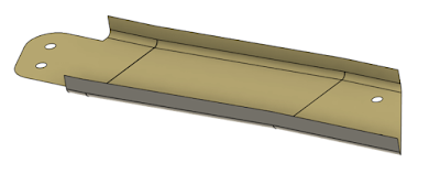
The part with all but the outer profile removed.  
Now that I had only this surface, I was able to return to the solid workbench and use the thicken tool to get the final shape I needed.


In Conclusion

So is this the only way to do it?  I doubt it.  But it did get the result I was after in a way I was happy with. I'm sure someone out there has a different way of doing it, they may prefer it.  And maybe someone out there has a way that's truly better.  I would be thrilled if they do and I hope they share it!

How would this part be made in real life? 

This is one place that I'm not an absolute expert, so I encourage others to chime in.  But I do have some experience making sheet metal this way.

In production, a blank would be placed in a die, possibly using two of the holes to locate the part.  Then a press would push the two die halves together, forming the part in one operation.

Here's a pretty good video on this process used for the ribs on an aircraft wing.

If the part is made in low production, A form block can be used, made out of wood or metal.  The blank is then formed using a hammer.

He's a video on that process. While this video shows the process being done for steel, aluminum would be done in a similar manner.

The part I modeled in Fusion 360 calls for 24ST aluminum, which is the equivalent of 2024-T3. I know that 2024-T3 can crack when formed around tight bends, so it's possible they would have used 2024-0 (dead soft) and heat treated to the -T3 condition afterward.  But that's one place I'd have to defer to the sheet metal experts, feel free to chime in!

And that's it, I hope this video was informative!

A Final Addendum, Murphy's Law Strikes! 

As I finished up this post, I tried the shell one more time.  Guess what! It worked! It seems I was just not quite getting the picks and clicks right when I tried it earlier.  But I decided to go ahead and share the post anyway because I still feel it's a viable alternative. 
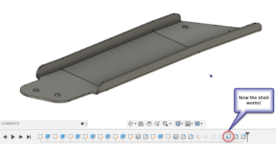
It figures! The shell does work!


Thursday, March 19, 2020

A Brief Summary of Drafting, Modeling, and Making Hydraulic Ports

Somewhere, someone is saying "It fit when I modeled it in the compuuter!"
CAD systems are wonderful tools, but, they're still tools, and largely reliant on the person pushing the mouse.

I was reminded of this when talking to a colleague about the standard hydraulic ports we use.

I know, riveting, right?

The conversation eventually turned to how the ports are called out on the drawing, and how we didn't learn this part of it in engineering school.

I recalled a time when I didn't know the standard, and how mysterious the process seemed to me as a young engineer

But when I was just a young lad, there was a crusty old salt with a black substance on his fingertips.

I'm not sure if it was grease, ink, or pencil lead. It may have been a combination of all of it.  Regardless, he helped set me straight.

So I decided I'd share what I know about the design, modeling, and drafting of hydraulic ports, in the hope that maybe it'll help someone else who faces a similar challenge..

The ports in question are "straight thread o-ring ports". In short, it's a port that allows an o-ring to be squeezed between the port wall, and the hydraulic fitting. This is shown in the image below.


The o-ring is compressed between the fitting and the wall of the port, making for a good seal.

It would stand to reason that the geometry to create the seal is pretty specific, and you'd be right.  That's where the standards come into  play. Somewhere, in the past, someone put a lot of work into figuring this out!

The one I use most at work is the AS5202 standard, it's the one shown in this image above. There's a lot of little details in there, fairly tight tolerance dimensions, angles, and surface finishes.

I won't go into all the dimensional details here, but for reference on the different port sizes and dimensions, the Parker Hannifin document can be referenced here. Rumor has it they know a thing or two about fluid fittings! The AS5202 port data can e found at the top of the document.

So, given that these dimensions are standardized, how do you make these ports?

I'm not a leading authority on the subject, but I know of two ways to make these ports.

The first, is get one of those fancy CNC machines and do some programming.

The other, is to get a tool that already has the port profile cut into it.  Then all you need is a standard mill.  You might even be able to use a drill press, but I'd defer to a real machinist on that one!

The threads are added in a secondary operation.

An example of the tools can be found at the Scientific Cutting Tools catalog page here.

AS5202 Port Tool. Image from Scientific Cutting Tools Catalog above

If you'd like to take a detour and see a machinist using a similar tool to make this port, you can check out the YouTube video here.

So now there's a discussion on the port, and how it's made.

But, how would you call these out on a drawing? While I'm sure everyone has their own method, one thing that could be taken away from this is to.... .use the standard.

Just callout the port: "by the standard"!

An example of a typical port callout
That covers some of the "big stuff", but here's a couple of trivia notes for you.

The dash means someting!

If you look at that document, you'll notice the column "tube dash number". That's a standard that seems to be one of those that the initiated assume that everyone knows. 

Notice in the image below, taken from the Parker Hannifin catalog.  You'll notice there's a column for "Equivalent Dash Nmmber", as well as a column for "Tube OD Minimum".

Now, if one takes the dash number, and divides it by the number "16", you'll end up with the Tube OD.  It's like they did it on purpose!

So if you're using -4 tubing (.250 inches), any fitting using a -04 dash number will work.

\
An example of a fittings and tubes

The standards change, but the geometry doesn't.


You might have notice that there are three standards that are listed as "Superseded" in the Parker Hannifin catalog.  And that's because the standards have changed over the decades, but the actual geometry has changed little, if any.

Some of you may even know it by the older designations!

I guess they had the geometry right even then!


The "Supersedes" comment gives you a brief history of the port.


In Closing....

I hope this little blurb was helpful. While it may be mundane and boring to some, I actually think it's interesting.  So take a look, see if it, or some form of the information helps you out.

Happy designing!