Find us on Google+ Inventor Tales: Fusion 360
Showing posts with label Fusion 360. Show all posts

Thursday, February 11, 2021

Getting Jacked - A Simple and Clever Way to Separate Parts

One thing using 3D CAD programs has taught me, programs like these can make assembling parts together a piece of cake! With just a few clicks, parts can be quickly placed into position.


3D CAD systems have many ways of assembling components


But just because a constraints allow us to easily assemble and disassemble parts, doesn't mean that it will be so easy to do on the assembly line, or during maintenance. 


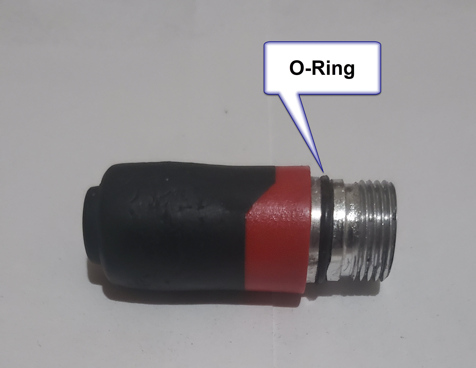
One example is a seal, such as a gasket or packing that locks the two mating parts together. For example, in the image below, the O-ring creating the seal may cause enough friction to prevent the flanges from being easily separated. 


The O-ring sealing the components could be enough to "friction lock"
the assembly, making it difficult to take apart.


One option would be taking a screwdriver or another prying device between the flanges and pry like you're opening a casket of pirate treasure.  But while a tempting option, wedging a prybar between the flanges could result in damage to the flanges.  If the flanges are made of a soft material, such as aluminum, the odds of damaging the parts goes up significantly. 


But the designers of old did come up with a more elegant way of separating these... sticky problems. 


Many times, assemblies such as these will have tapped holes that appear to go nowhere.  They don't have a corresponding hole in any mating part.  They just appear to.... be there.

Why were these holes put there? They do have a purpose!


That's because they aren't there for the purpose of assembling parts.  They're for disassembling parts. 


They're called "jacking holes". By carefully threading screws into these holes, the two flanges can be pushed apart evenly without damaging the parts making up the assembly. 


Using a socket head cap screw to separate the flanges.


It's a simple, and elegant way of solving a challenge. 


So if you should find yourself having to disassemble an assembly similar to what I've shown here, look for those jacking holes and see if it can make your life easier. 


And if you find yourself designing a component that may present a challenge, perhaps adding a couple of jacking holes might make for a design that's easier to disassemble when the need arises! 


Opposing jacking screws help separate the flanges evenly!


About the Author:

Jonathan Landeros is a degreed Mechanical Engineer and certified Aircraft Maintenance Techncian. He designs in Autodesk Inventor, Siemens NX, at work, and Autodesk Fusion 360 for home projects. 

For fun he cycles, snowboards, and turns wrenches on aircraft. 


Standard Parts Used on this Project

A569-343 Viton O-ring - McMaster Carr Part Number 9464K173


Buna-N -343 Backup  Ring - McMaster Carr Part Number 5288T372


1/2-13 x .500 Long Socket Head Cap Screw - McMaster Carr Part Number 92185A712

Sunday, September 13, 2020

Double Checking Your Work and Subverting Mr. Murphy

I once saw a graph that showed the cost of making a change in the CAD model vs  further down in the product design cycle


Spoiler alert! It gets more expensive as you move from design, to prototype, to production.  

One need only to cases like the Takata airbag recall, or Boeing 737 Max grounding or the impact of the impact of a a production level design change in in money, company reputation, and tragically, in lives lost. 

But I'm not here to write about such heavy topics. The example I'm choosing to document is a much lower stakes version of the same thing.  It's just a basic hobbyist example that at worst, is inconvenient and marginally embarrassing.

It's an access panel based on something you'd find on an aircraft. It's a concept for a potential future hobby project. I built one back when I was in school.

So I happily modeled away in Fusion 360, creating sheet metal parts and placing fasteners from McMaster Carr

After spending a couple of evenings of casual modeling, I was done! I took that moment we all love, I leaned back, looked at my work proudly, then prepared one last check before I took my little victory lap.

The completed inspection hangar, or so I thought...

And that's when I saw it. 

The countersunk rivets I had installed were the wrong ones. I'm not sure how I missed it initially, but obviously I did. 

So first, what's wrong with the rivet? 

It's a rivet with a 78 degree countersink, which means the countersink extends to the second sheet of metal being riveted.  This is a big no-no. When the countersink extends into the second piece of metal, the larger hole required in the first sheet of metal makes for a weaker joint.

The wrong rivet. I did match the countersink angle to match the rivet for clarification.


The incorrect rivet for this application. The countersink angle is too steep


The correct rivet is a 100 degree rivet. The shallower angle prevents the head from punching into the second sheet of metal. That means a stronger, and safer joint.

The 100 degree rivet, the correct one for this application. 
I know in the model the rivet does appear to just clip the second sheet.
But past experience has taught me that this combination does work.

The shallower angle of the 100 degre countersink makes a stronger joint

So that's the technical aspect of it, what's the other lesson?

I suppose the first lesson is make sure to check the hardware before you put it in. But we all make mistakes. That's where double checking comes in. 

A final check can help prevent the last little "oops" from slipping through. Even though we can't eliminate them all, we can reduce them with a little time. 

For those of us working in industry, a second set of eyes never hurts. In some places, multiple checks on a drawing are required. It's not a bad practice at all, one I think should be taken advantage of whenever possible. 

Some may argue it takes time, but it takes much less time than undoing a costly mistake. 

I've worked in maintenance shops where "second eyes" is a standard policy on items such as fuel system repairs. In other words, the person performing the work checks his work, and then a second technician or inspector checks it again. There often are even signatures required to prove that this step was performed. 

But that's it for today's anecdote. I re-learned a few lessons in a safe environment where the only bruise was to my pride. 

I hope you can take a few lessons from this musing, and keep making cool stuff! 

About the Author:

Jonathan Landeros is a degreed Mechanical Engineer and certified Aircraft Maintenance Techncian. He designs in Autodesk Inventor, Siemens NX, at work, and Autodesk Fusion 360 for home projects. 

For fun he cycles, snowboards, and turns wrenches on aircraft. 


Additional Resources: 

A nice  rundown on different types of rivets by- Hanson Rivet and Supply

A wealth of knowledge on general airframe repairs (start at page 4-31 for the Riveting Section) -Aviation Maintenance Technician Handbook 

Standard Parts Used on this Project.

.125 Diameter, 78 Degree Solid Rivet (The Wrong One) - McMaster Carr Part Number 97483A075

.125 Diameter, 100 Degree Solid Rivet (The Right One) - McMaster Carr Part Number 96685A170

10-32 Floating Nut Plate - McMaster Carr Part Number 90857A129

.094 Diameter Rivet (to Fasten Nut Plate) - McMaster Carr Part Number 96685A143

#10 Flat Washer - McMaster Carr Part Number 92141A011

10-32 Pan Head Phillips Screw - McMaster Carr Part Number 91772A826


Friday, July 31, 2020

Designing for O-Rings and Reusing Design Features in Fusion 360

O-ring seals are hard to avoid as a mechanical designer of any type. They can be found just about anywhere that fluid, gases, or debris needs to be kept in or out of something.

An O-Ring on the end of a flashlight

As simple as they appear, there's enormous amounts of research invested in that simple, pliable polymer ring.

How does this affect the designer? Typically by the pages and pages (real or virtual), containing tables and tables of o-ring groove dimensions.
O-Rings from a
different flashlight.


When it comes time to apply that to a 3D modeler, that means creating the o-ring grooves, including some tight tolerances. The process can be extremely tedious, especially when there are multiple o-rings of different sizes involved.

So how can a user create these o-ring glands as painlessly as possible? Sure, many of us have placed the same feature so many times we have the dimensions memorized. But why do that, unless you like that sort of pain? 

While I can't speak for every CAD tool, many tools have wizards that will help create o-ring glands, as well as other common design features. Autodesk Inventor has iFeatures, Solidworks has Library Features.

Fusion 360 doesn't have a library feature as such, at least that I've found at this point. But, there is a way to create such a thing and make life a little easier.

Preparing the O-Ring Gland

The first step, is acquire the documentation with the necessary dimensions. Lately I've become partial to the Parker O-Ring Handbook myself, seeing how they know a thing or two about sealing. 

For this example, I'll use a -018 o-ring. It's a static (non moving) seal, and I'll use the male gland as an example (stop snickering, that's Parker's terminology). 

Gland Schematic from Parker O-Ring Handbook

Here are the dimensions pulled from the design tables

From Table 4-1

C=.860/.861
F = .750/.754
Corner break = .005 


From Table 4-1A 

W = .105/.110 


From Table 4-2

R = .005/.015 

O-Ring Groove Radius

Modeling the O-Ring Gland

Before creating any models in Fusion 360, enter the relevant values into the parameters dialog box. This seems like extra work, but I think it makes creating models with new sizes easier.

The Fusion 360 Parameters screen with the o-ring parameters started


Now, draw the profile of the o-ring gland, using the values from the parameters table. 

The gland profile sketched and dimensioned.

Next revolve the profile into a solid. Now, we have a solid representing the shape of the groove.

The o-ring groove revolved as a solid.

Believe or not, that's it for creating the gland. Saving it will make it available for other components to use.

Inserting the O-Ring Gland

What's needed next is a component in need of an o-ring. In this case, I've modeled a simple plug in Fusion 360.  It's similar to the threaded plugs found here on the McMaster Carr site.  I've just moved the gland location to make things a little more clear.

A threaded plug

To place the o-ring gland, right click on the file in the Data Panel and choose "Insert into Current Design".  This places the gland into the model


This inserts the gland into the plug.  Now it can be positioned by using the Move/Copy command, or assembled using the Joints command.

Placing the o-ring gland. The Move\Copy command is shown.

After positioning the gland, use the combine command to subtract the gland volume from the plug.  


Once the Combine Command has been committed, the plug is finished.  And you also have a -018 gland ready to use in your next design!

The finished plug. (Don't forget to hide the original solid!)


But undoubtedly, other o-ring sizes will be needed.  That's where using the parameters can come in handy.  Just copy the existing gland and rename it, then enter new values in the chart.


Summing it Up

I only used static o-ring grooves for this post.  There's also dynamic (moving) seals, face seals, glands that use backup rings (for higher pressures), and probably something else I'm not mentioning. I just can't get into them all, but the data is out there. It's just a matter of looking and asking questions.

As for desigining the gland, the steps I've shown here are for Fusion 360. But if you've made it this far, I hope it's the process you take away. I hope that you can find it helpful, and perhaps can apply it to what ever product you use for your design.

At the very least, I hope you walk away with resources that you can use when the time comes to design for o-rings.

And lastly, here's the list of resources I used in this post.

Parker O-Ring Handbook -  PDF Download
McMaster Carr - Website
Milwaukee Penlight - From the Home Depot Website 
Mag Instruments Maglite - Mag Instruments Website
Autodesk Fusion 360 - Autodesk Website

Saturday, March 28, 2020

A Challenging Channel - Modeling a Sheet Metal Channel in Fusion 360

On a morning this weekend, while hanging out at home with my coffee in my hand, I decided to play with Fusion 360.  I had a part picked out that looked simple enough.

The finished part. It looks simple, but it hides a suprise

The part I chose looked to be a simple sheet metal part.  It looked to be a simple enough part, but it did have a joggle in it that complicates things a bit.

The joggle that changed how this part was made
Since it's got this joggle, it can't be easily modeled using sheet metal tools.

The sheet metal version wasn't quite what I was after.
So I decided to model it using the "regular" modeling tools.

I also decided I'd document how I did it here, for both posterity's sake, and in the hopes that it might give another struggling user an idea.  I won't go through every single step, but I will give an overview that hopefully encompasses the high points.

The first thing I did was model the envelope.  I nothing more than an extruded rectangle.  A "brick".

The starting point. An extruded rectangle representing the parts outer dimensions.

Next came the process of carving out the shape. I started with the joggle.

The joggles cut into the part. I've turned one of the sketches on to make it more visible.


Once the joggle was in, it was a matter of adding the remaining features, including the outside fillets that represent the outer bend radius.  Notice that the part is still a brick.  It's just a brick with some nice looking features!

The brick has all the features of the sheet metal part now.
This is where my original plan went wrong. My plan was to use the shell command to create the inner profile.

But for some reason, I couldn't select the surfaces I wanted.  I always ended up selecting a surface I didn't want.

So it was time for plan "B".  I switched to the surfacing workbench and used delete face to remove all the faces except those that represented the outer profile of the part.

The part with all but the outer profile removed.  
Now that I had only this surface, I was able to return to the solid workbench and use the thicken tool to get the final shape I needed.


In Conclusion

So is this the only way to do it?  I doubt it.  But it did get the result I was after in a way I was happy with. I'm sure someone out there has a different way of doing it, they may prefer it.  And maybe someone out there has a way that's truly better.  I would be thrilled if they do and I hope they share it!

How would this part be made in real life? 

This is one place that I'm not an absolute expert, so I encourage others to chime in.  But I do have some experience making sheet metal this way.

In production, a blank would be placed in a die, possibly using two of the holes to locate the part.  Then a press would push the two die halves together, forming the part in one operation.

Here's a pretty good video on this process used for the ribs on an aircraft wing.

If the part is made in low production, A form block can be used, made out of wood or metal.  The blank is then formed using a hammer.

He's a video on that process. While this video shows the process being done for steel, aluminum would be done in a similar manner.

The part I modeled in Fusion 360 calls for 24ST aluminum, which is the equivalent of 2024-T3. I know that 2024-T3 can crack when formed around tight bends, so it's possible they would have used 2024-0 (dead soft) and heat treated to the -T3 condition afterward.  But that's one place I'd have to defer to the sheet metal experts, feel free to chime in!

And that's it, I hope this video was informative!

A Final Addendum, Murphy's Law Strikes! 

As I finished up this post, I tried the shell one more time.  Guess what! It worked! It seems I was just not quite getting the picks and clicks right when I tried it earlier.  But I decided to go ahead and share the post anyway because I still feel it's a viable alternative. 

It figures! The shell does work!


Thursday, March 19, 2020

A Brief Summary of Drafting, Modeling, and Making Hydraulic Ports

Somewhere, someone is saying "It fit when I modeled it in the compuuter!"
CAD systems are wonderful tools, but, they're still tools, and largely reliant on the person pushing the mouse.

I was reminded of this when talking to a colleague about the standard hydraulic ports we use.

I know, riveting, right?

The conversation eventually turned to how the ports are called out on the drawing, and how we didn't learn this part of it in engineering school.

I recalled a time when I didn't know the standard, and how mysterious the process seemed to me as a young engineer

But when I was just a young lad, there was a crusty old salt with a black substance on his fingertips.

I'm not sure if it was grease, ink, or pencil lead. It may have been a combination of all of it.  Regardless, he helped set me straight.

So I decided I'd share what I know about the design, modeling, and drafting of hydraulic ports, in the hope that maybe it'll help someone else who faces a similar challenge..

The ports in question are "straight thread o-ring ports". In short, it's a port that allows an o-ring to be squeezed between the port wall, and the hydraulic fitting. This is shown in the image below.


The o-ring is compressed between the fitting and the wall of the port, making for a good seal.

It would stand to reason that the geometry to create the seal is pretty specific, and you'd be right.  That's where the standards come into  play. Somewhere, in the past, someone put a lot of work into figuring this out!

The one I use most at work is the AS5202 standard, it's the one shown in this image above. There's a lot of little details in there, fairly tight tolerance dimensions, angles, and surface finishes.

I won't go into all the dimensional details here, but for reference on the different port sizes and dimensions, the Parker Hannifin document can be referenced here. Rumor has it they know a thing or two about fluid fittings! The AS5202 port data can e found at the top of the document.

So, given that these dimensions are standardized, how do you make these ports?

I'm not a leading authority on the subject, but I know of two ways to make these ports.

The first, is get one of those fancy CNC machines and do some programming.

The other, is to get a tool that already has the port profile cut into it.  Then all you need is a standard mill.  You might even be able to use a drill press, but I'd defer to a real machinist on that one!

The threads are added in a secondary operation.

An example of the tools can be found at the Scientific Cutting Tools catalog page here.

AS5202 Port Tool. Image from Scientific Cutting Tools Catalog above

If you'd like to take a detour and see a machinist using a similar tool to make this port, you can check out the YouTube video here.

So now there's a discussion on the port, and how it's made.

But, how would you call these out on a drawing? While I'm sure everyone has their own method, one thing that could be taken away from this is to.... .use the standard.

Just callout the port: "by the standard"!

An example of a typical port callout
That covers some of the "big stuff", but here's a couple of trivia notes for you.

The dash means someting!

If you look at that document, you'll notice the column "tube dash number". That's a standard that seems to be one of those that the initiated assume that everyone knows. 

Notice in the image below, taken from the Parker Hannifin catalog.  You'll notice there's a column for "Equivalent Dash Nmmber", as well as a column for "Tube OD Minimum".

Now, if one takes the dash number, and divides it by the number "16", you'll end up with the Tube OD.  It's like they did it on purpose!

So if you're using -4 tubing (.250 inches), any fitting using a -04 dash number will work.

\
An example of a fittings and tubes

The standards change, but the geometry doesn't.


You might have notice that there are three standards that are listed as "Superseded" in the Parker Hannifin catalog.  And that's because the standards have changed over the decades, but the actual geometry has changed little, if any.

Some of you may even know it by the older designations!

I guess they had the geometry right even then!


The "Supersedes" comment gives you a brief history of the port.


In Closing....

I hope this little blurb was helpful. While it may be mundane and boring to some, I actually think it's interesting.  So take a look, see if it, or some form of the information helps you out.

Happy designing!


Monday, June 24, 2019

3D Printing Threads - A Few Tricks I Picked Up

When I first took on 3D printing, the subject of threaded fasteners always made me a bit nervous.  While I try to use actual hardware whenever possible, there are cases where the thread isn't used on a simple part that can be purchased from McMaster-Carr.
An example of a part requiring a thread

That meant, eventually, I was going to be faced with making a thread. What made me nervous was how to I make the thread work? Especially since I typically deal in machine threads? Machine threads can get pretty fine. 

First, I want to get the acknowledgements out of the way. I didn't come up with these ideas on my own.  I started by watching the following videos, and adapted them to fit my needs.  

The first is from KETIV Technologies, and the second, from 3D Printing Nerd.  Those videos are certainly worth taking a look. But I did need to tweak their procedure to get the result I needed.

So here's a quick rundown of the procedure I used, with a couple of changes I made to make it work for me.  

I'll be using Fusion 360 for this example.  I've found it gives me the best results, but I'm sure other CAD tools can perform similar functions.
 
Here we go! 

Thread Reliefs are Not a Relief

First of all the part I work with often have thread reliefs modeled in. I found out the hard way that these can sometimes interfere with the thread lead in.  I've had the best luck deleting them and making sure the thread starts right at the end of the desired starting point. 

The thread relief has been deleted.
Click image to enlarge

Tune up the Virtual Tap and Die Set

After deleting the reliefs, the modeled thread needs to be added.  This may be done by editing an existing thread, or creating a new one if a thread feature doesn't exist. Fusion 360 has a check box that models the thread,  Other programs have different methods of adding the thread. 

The modeled thread and dialog box.
Click to enlarge image.

Practice Your Scales

Now comes my challenge and the solution I found for that challenge. I needed to scale the thread to increase the clearance between the mating thread so it will thread smoothly. But I can't scale the entire part, because the rest of the geometry needs remain the same size.  

So I split the part into two different solids.  In this case, I used an extruded surface as my splitting surface.  The diameter of the surface is only slightly smaller than the minor diameter of the thread.  

Remember the goal is to scale the thread, not anything else! 

An example of the surface that becomes the cutting tool.
Click image to enlarge

Now the solid containing the thread can be scaled. For the parts I work with, I only scale radially.  The thickness is left alone. 

Scaling the solid that contains the thread.
Note the use of Non-Uniform Threading
Click image to enlarge
As far as the amount to scale, I've found that it varies.  I've done between 0.5 and about 5 percent.  With larger percentages working for smaller threads. However, I'm still working on the guidelines, so I wouldn't consider these numbers absolutes.  

Check the Thread Clearance

As a final check, I compare the part to it's mating thread, assuming I have it, and if I have what looks like a good clearance, I roll with it. 

Comparing the mating threads to eyeball the clearance.
Click image to enlarge


I know it's not very scientific, but so far, it's been effective. 

Glue it all Together with the Combine Command

For my final step, I combine the solids back into one.  Now the part is ready to be exported as an STL file, and imported into your slicer. 

Combining the two solids back into one.
Click image to enlarge


Speaking of slicers, I use Simplify3D at work. And what I've also found works best is to remove any supports that are automatically generated inside the thread. I've found they aren't needed, it's just that Simplify3D thinks they are.  

And thus far, these guidelines have worked well for me.  Feel free to take them and give them a try, and modify them as you see fit!
Good luck! I hope this is helpful! I hope you can take these ideas and use them as seeds to develop your own. 

And please share your tricks with others! 

Friday, May 31, 2019

Eighteen Months of 3D Printing - Where Have I Learned to Use It?

Eighteen months ago, I took on the task of running the 3D printer at work.  It's a Fusion3 F400-S, similar to the upgraded 410 shown on Fusion3's website.

It's a FDM (Fused Deposition Modeling) printer, in other words, it melts plastic and lays it down one layer at a time until it produces the desired result.  '


At least that's what's supposed to happen!

All I can say is that it's been fun, frustrating, rewarding, and discouraging at various stages of the journey.  I've tasted the sweet joys of victory, and I've muttered the bitter "F-Bomb" of defeat.

Most of all, I've realized that while I've learned a lot, I'm far from an expert. Because of that, I'm not going to tell you how to make a successful print.  There are plenty of people who are doing that, and frankly, they are much more knowledgeable than I.

But what I can share are my experiences watching our 3D printer making an impact in our design process.  So here I go, showing a few places where having a 3D Printer has shown itself to be a helpful part of our design processes.

One disclaimer before I get started.  I can't share the real parts online.  Words like "proprietary" and "security" start getting thrown around.  So I have to use "surrogate" parts that represent the concept.

Thanks in advance for bearing with me!

1) The "Show and Tell" 

There's nothing like holding a represenation
of the part in your hand.
When I think of 3D printing, this is the first application that comes to my mind.  It's simply a cosmetic print meant to give an idea of the "form and function" of the part.  In our case, it didn't do anything but give everyone a sense of size and shape. 

This might seem simple at first.  With 3D CAD Modeling tools, we can model our designs precisely.  So why "waste time" printing a part that's just "for looking".

Well, I know I've fallen victim to being able to zoom into a small screw until it looks like a table leg.  And with that, comes a distortion of scale that can affect those of us that live in the real world.

And I know I'm not the only one.  I've heard more than one person say, "I really didn't think about big/small that part is!"

A particular example comes to mind.  I was in a meeting where the projected image of the CAD model rotating on the wall was completely ignored because engineers and customers were drawn to the 3D printed model that represented a much more tactile experience that couldn't be experienced with the 3D model.

2) The "Assembly Test" 

This print is in reality a series of parts that make up an assembly.  It may even be a combination of real and printed parts.
A sample part with a real hydraulic fitting threaded into one hole

The purpose of this part is to ensure that the parts you've carefully designed can not only be put together, but put together easily.

I can see which fitting will have to get torqued in first! 
For example, can a bolt be inserted into the bolt hole, and once in there, can the wrench follow up and turn the bolt once it's in the hole.

3) Tooling and Covers

I've lumped these tooling and protective covers into the same category, partially because the two sometimes blend into each other, at least where I work.

An example of a protective cover that has a unique shape

Because the 3D CAD model exists, it can be relatively quick to create a negative of the part, then print that negative as quickly as a few hours.

An example of a cradle created by creating
a negative of the part. 
Sometimes these shapes are odd or unique, and can't be easily duplicated by the machine shop, or frankly, the machine shop just doesn't have the time to make them.

In any case, 3D printing provided us with the ability to create odd geometry quickly, without disrupting other operations.

In Conclusion

My intention here was just to share a few cases where I've found 3D printing helpful.  By no means is it comprehensive.  If anything, I hope it provides a few ideas, and dare I say, inspiration.

I think it's also important that we bear in mind that 3D printing is a new tool that can supplement existing tools.  Don't by a 3D printer thinking that you'll be able to shut down your machine shop, woodshop, or welding shop. .

So take these ideas and make them you're own.  And feel free to share in a comment if you have a good use for 3D printing in your home or office.

Acknowledgements