There are times when a component is placed in Autodesk Inventor, it doesn't take the orientation I want it to. It lays on it's side, back, etc. Every way but the way I want it.
Inventor can work with this just fine, but ultimately, I like my components sitting in a "natural" state.
Usually, I'll just unground the component, and assembly it to origin planes. It took little time, and got what I wanted.
But now, 2014 has added a new option, the ability to reorient a component during placement.
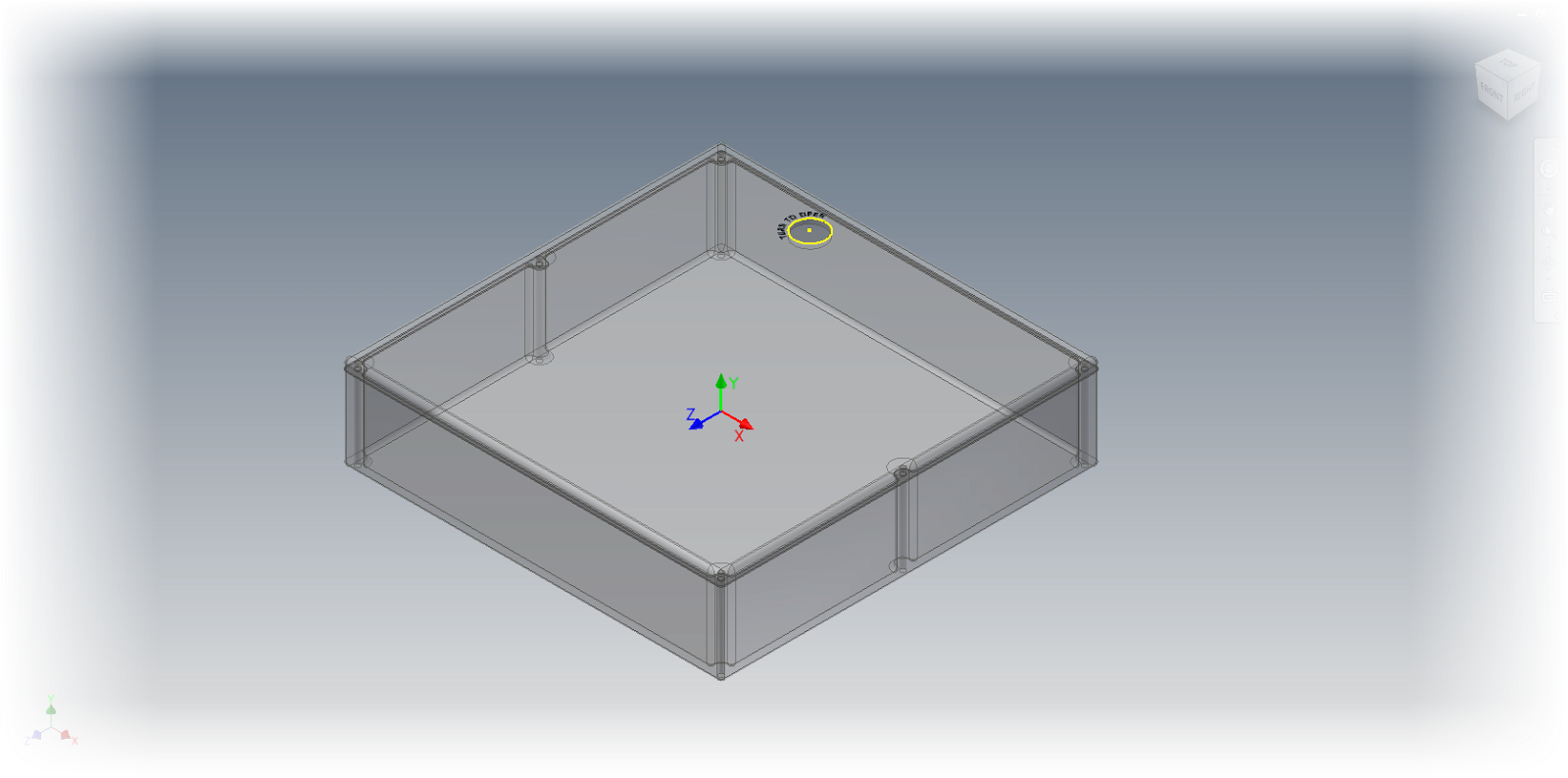
Let's start with an assembly, where I'm placing a metal container with
the Place Component command. Notice that the container is laying on
it's back. I want it placed on it's bottom, like it would be hanging on
a wall.
It's important to note in the image below, that I'm still looking at the preview. I haven't placed the component by left clicking yet.
The initial preview of the component placement.
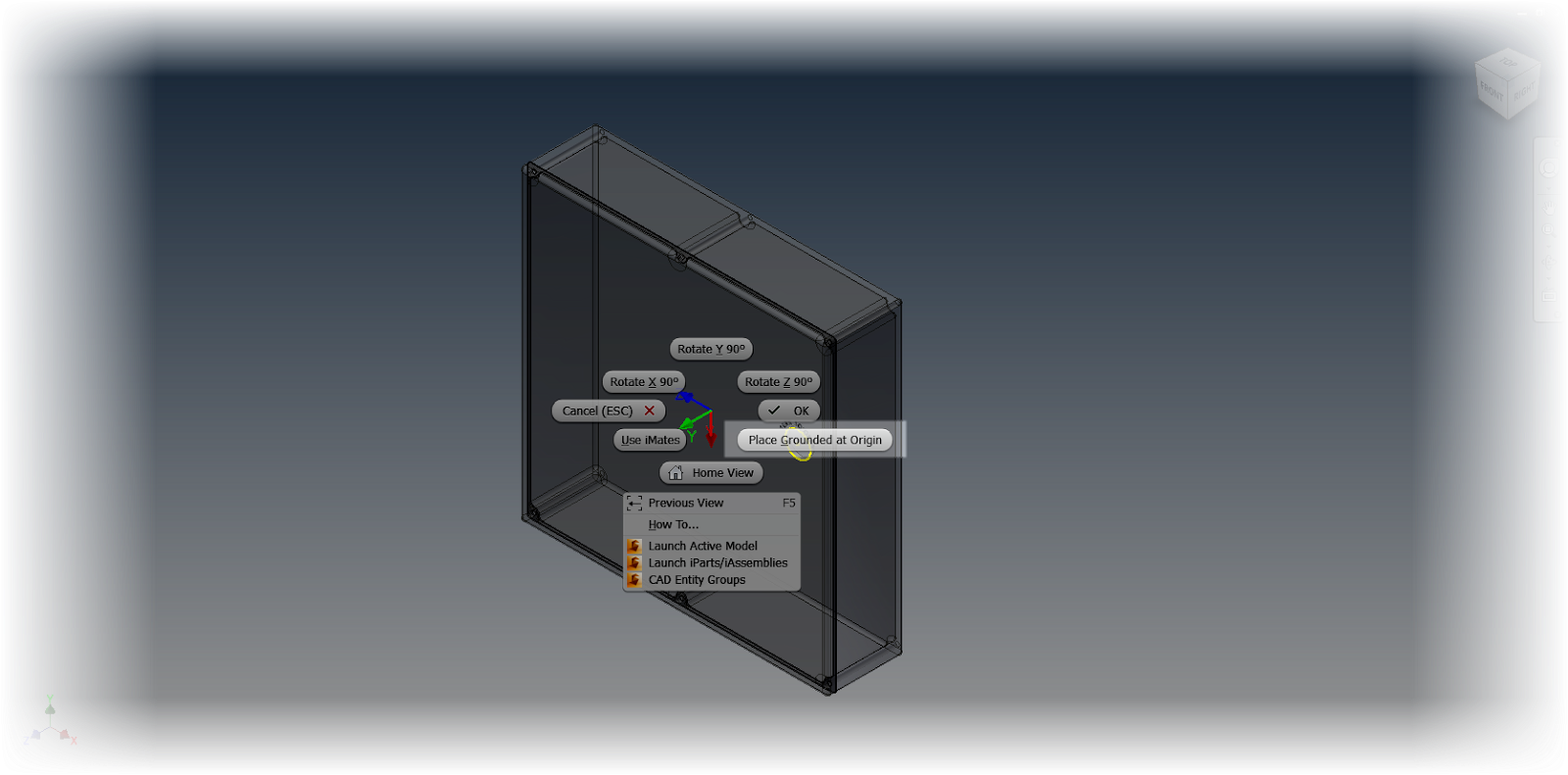
Now, with the preview on screen, I right click to see the rotation options. There are options to rotate around the X, Y, and Z axis in 90 degree increments.
Right clicking to see the rotation options.
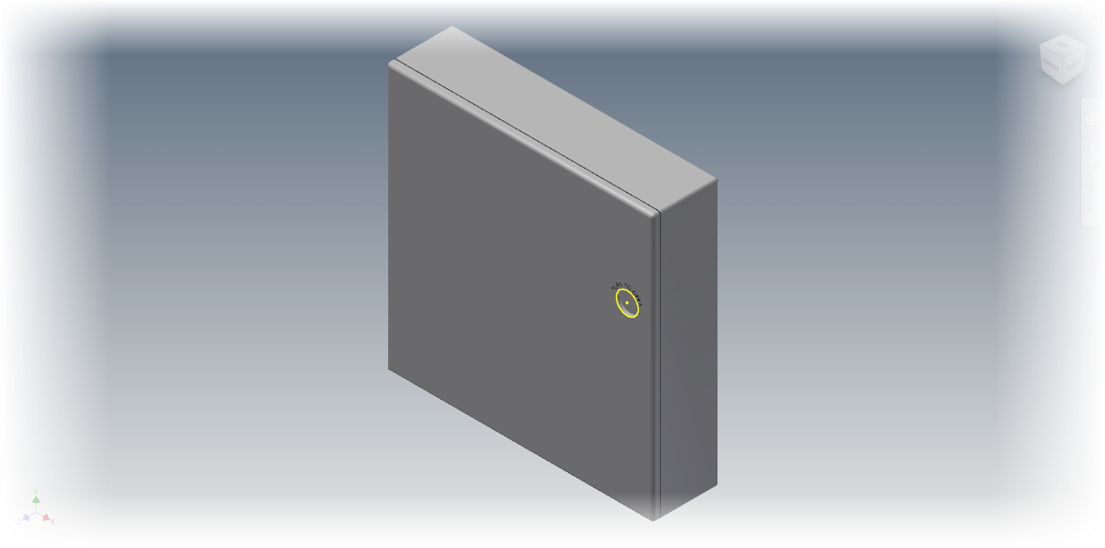
In this example, I've rotated round the X-Axis once, and Y-Axis three times. (It's a little like a combo on a game console!)
The corrected orientation
Finally, the component can be placed by left clicking or by right clicking and choosing Place Grounded at Origin
Placing at Origin
And that's all there is to it! The component is placed and ground, all in the orientation I want!
The component placed!
And below, here's the video portion of the post! I hope you find it helpful!
Sitting in my hotel room on a business trip to Dallas, Texas, I found myself taking a look at a new feature in Autodesk Inventor 2014, and thought I would go ahead and create a short post on it.
This new feature is "Show Relationship" in an assembly.
Activating this feature shows the relationships between constraints in the modeling window, in a graphical format.
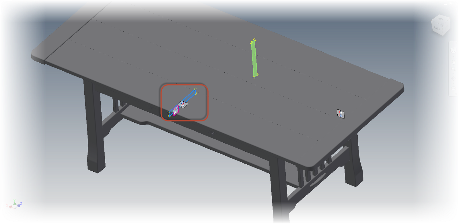
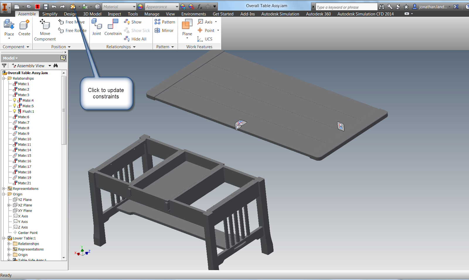
For this example, I'll use the Craftsman style coffee table I've used dozens of time before.
The constraint relationship glyphs showing on the Craftsman Style Table
By using a graphical representation, the constraint can be easier to visualize, modify, and delete.
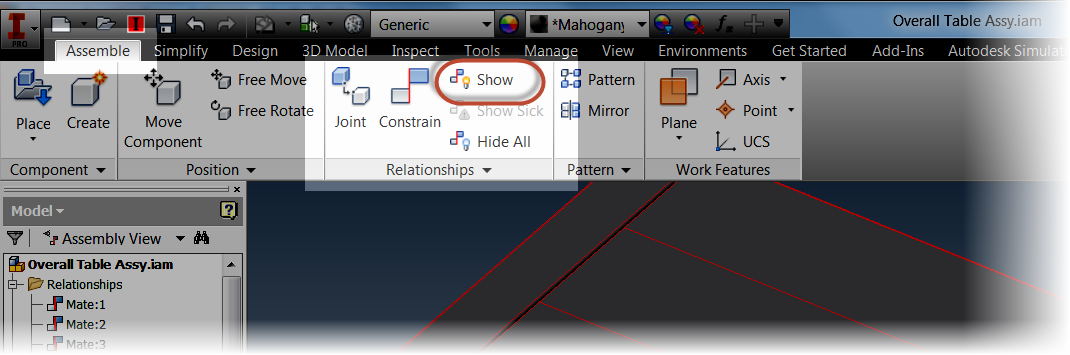
The first step to using the relationship is to show them. This is located on the Assemble Tab by clicking the Show icon.
The Show Relationships tool
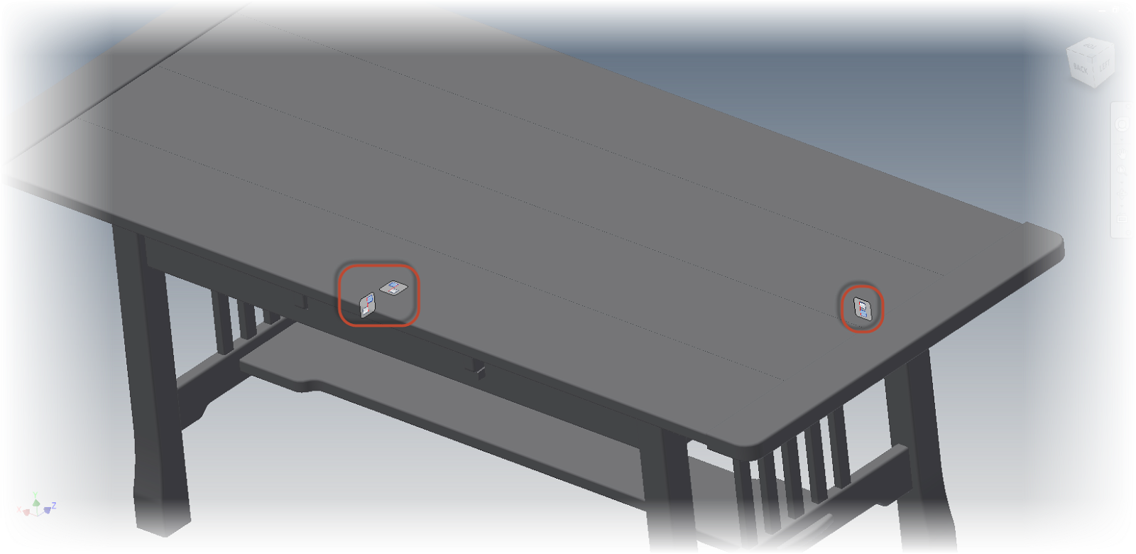
Once the icon is selected, I can choose the components I want to show the relationships for. In this case, I'm just going to look at the table top.
Glyphs will appear where the constraints between the table top and the lower table it's connected to.
The Constraint Relationship glyphs
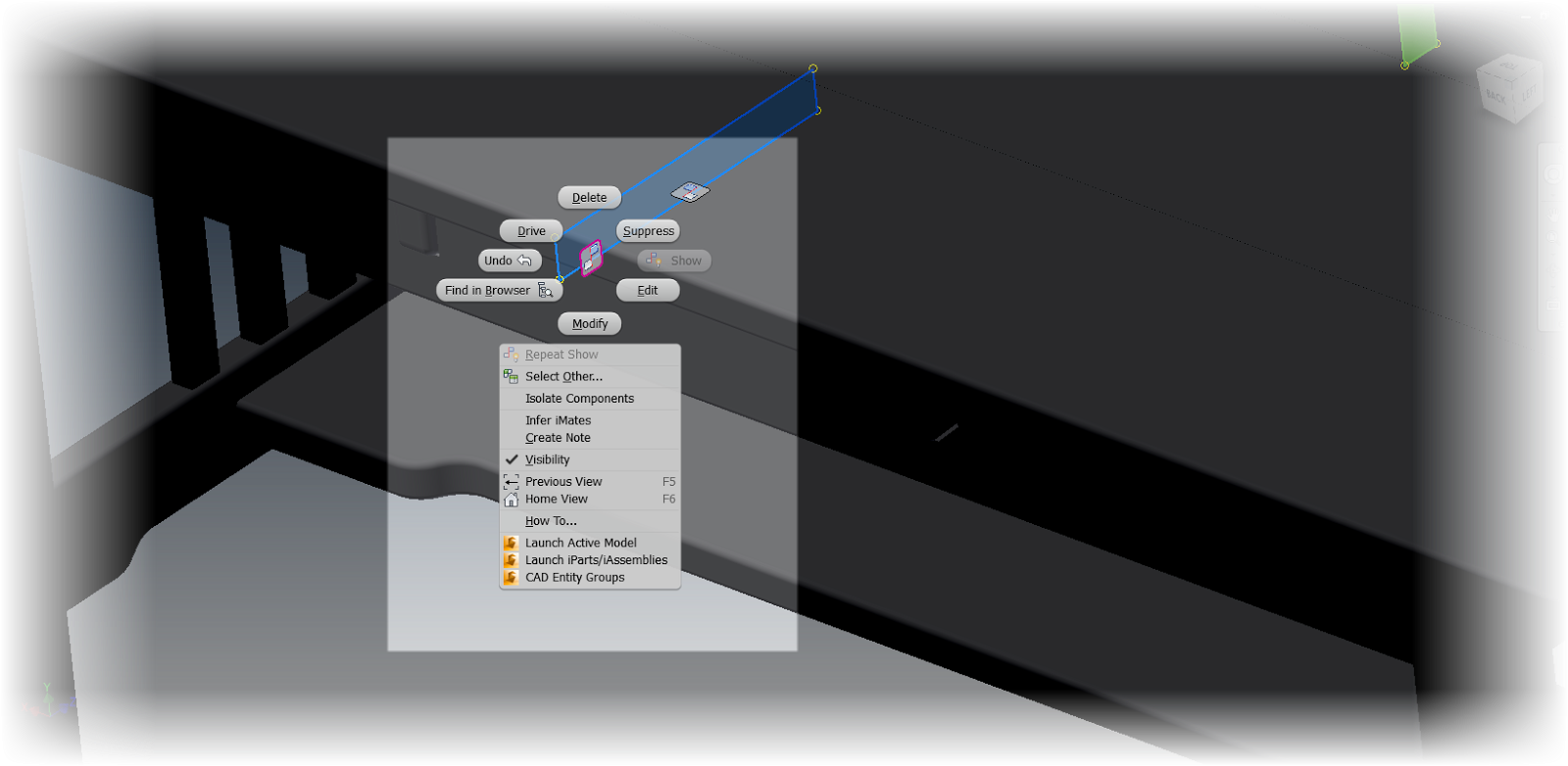
Right clicking on the constraint glyphs provides the operations that can be performed on this constraint, such as, Edit, Delete, and Suppress, among more.
Right clicking on a glyph will show the editing tools
If the component is moved using the Free Move command, "bands" appear that connect the constraint to its mating components while the command is active. After this I can right click and choose "OK" to complete the move.
Using the Free Move command to separate components
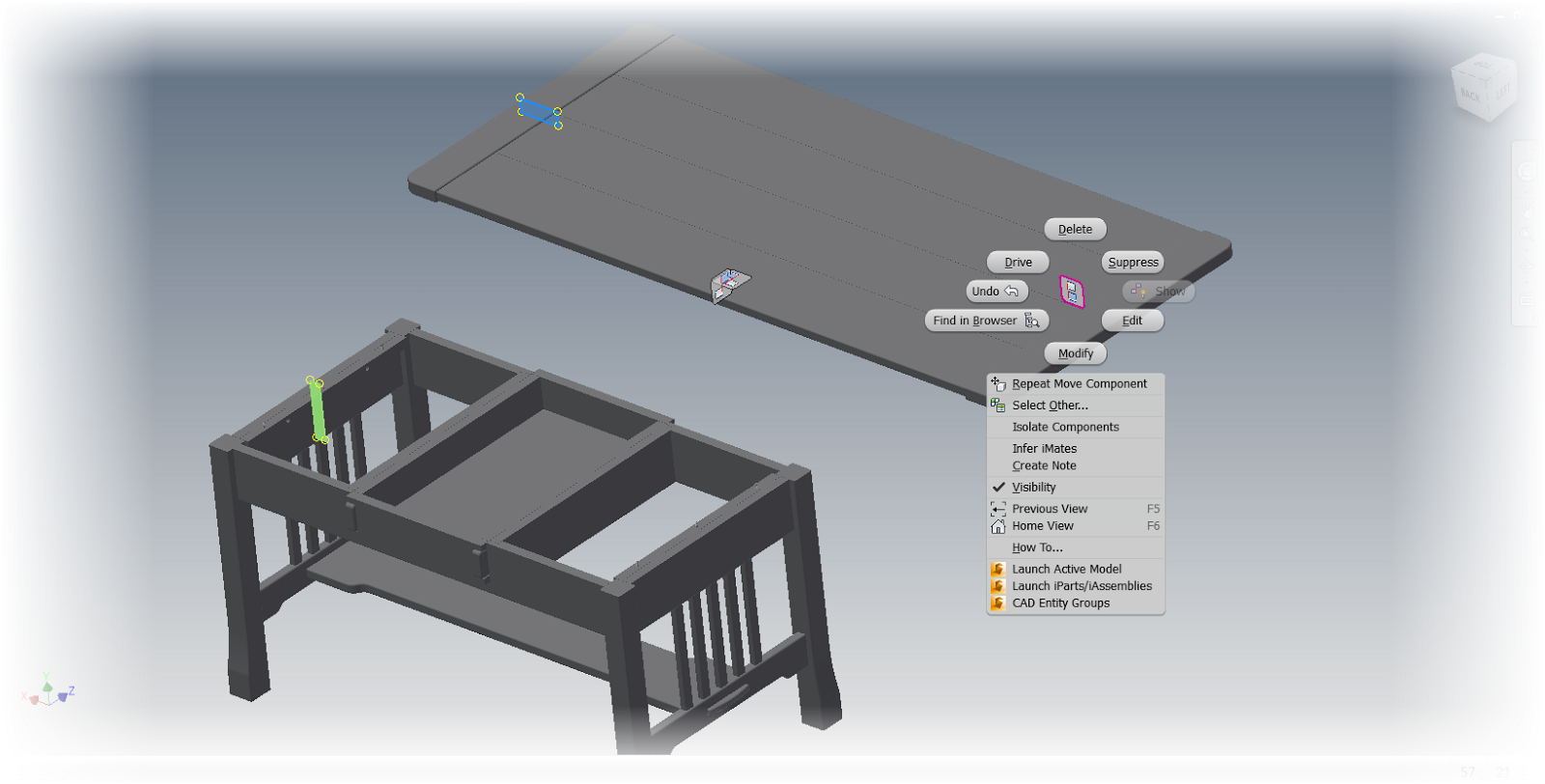
Clicking on the constraint will also highlight the geometry that the constraint is attached to, giving a quick graphical way of seeing how the constraint is being used to constrain the geometry. Just like before, right clicking on a constraint will show the options for that constraint
The components move apart, showing the right click options
Updating the assembly will update the constraints and return the component to its original position.
Updating the assembly will restore the constraints
But before I say "take this tool for a spin", there is on other place this tool can help out.
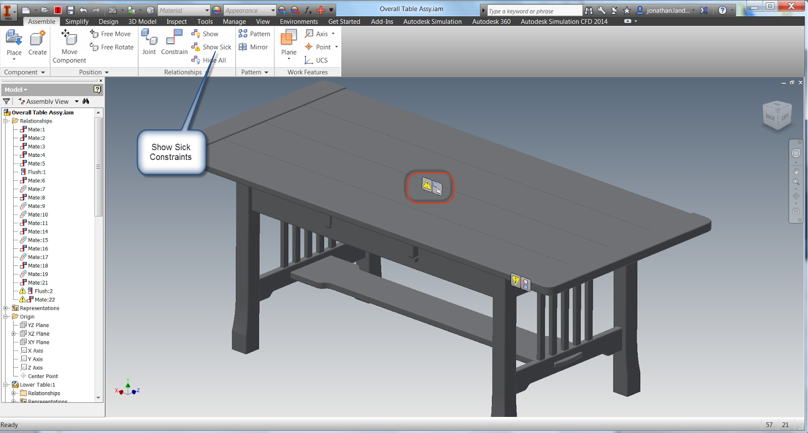
If there are "sick" constraints, such as conflicting constraints, can be graphically diagnosed using the Show Sick Relationships tool.
Showing Sick Constraint Relationship for diagnostic purposes.
With this ability, the Show tool can be used for editing, and for diagnostics!
So on that note, take this tool for a spin! And in addition, here's a video on the subject!
In that post, there was a comment that stated once the sketches were made visible, the option to "Get Model Sketches" was grayed out. Which is true.
Get Model Sketches is now grayed out
So how can the visibility of sketches if they're added to the model after the "Get Model Sketches" option is used.
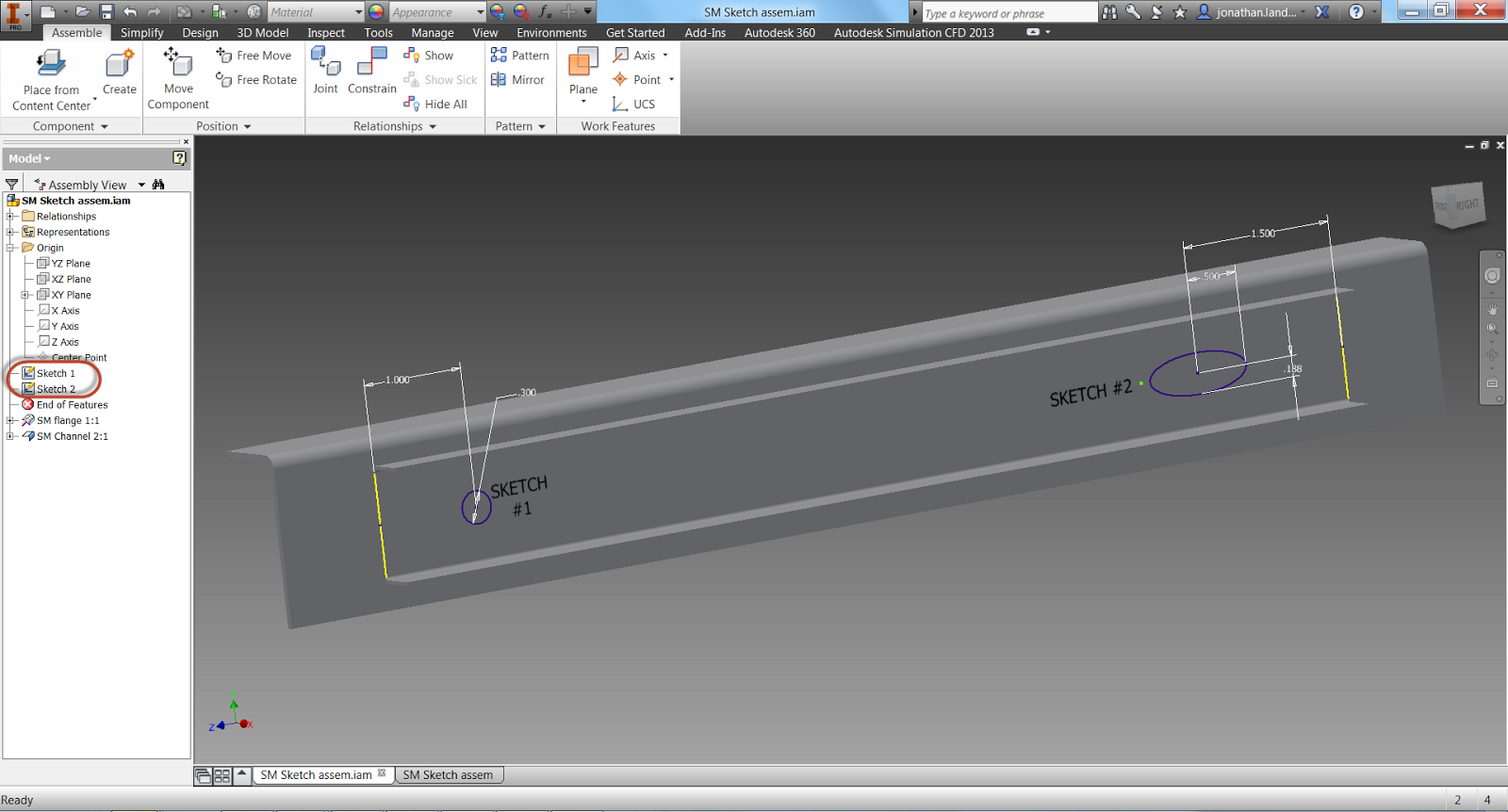
Here, I've added a second, distinct sketch in Autodesk Inventor 2014.
Note the sketches are separate
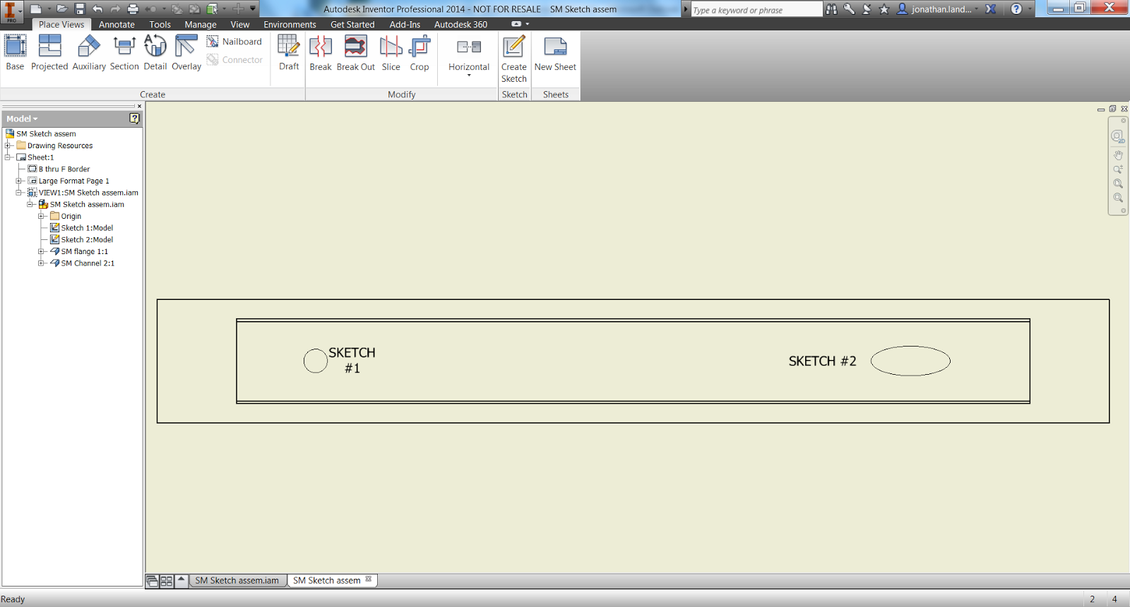
When I switch to the drawing, the sketch will automatically appear on the drawing, with no further interaction.
The second sketch appears
But what if I don't want to show both sketches. Perhaps one sketch represents a spot weld, and the other is just there for construction or a model only reference?
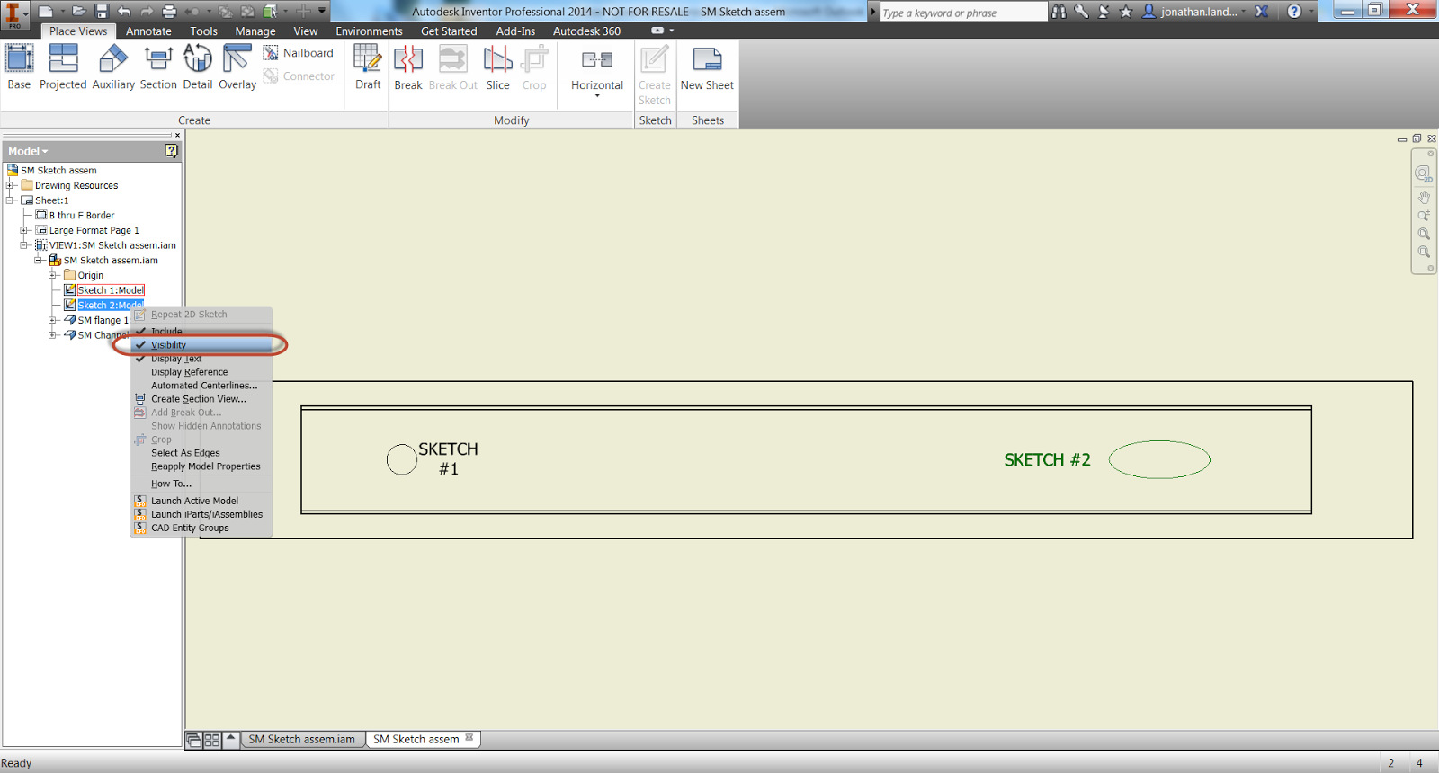
All that I have to do is right click on the sketch in the browser, and uncheck the "Visibility" option. The sketch will disappear and will no longer be shown. Showing the sketch will make the sketch visible again.
Now you see it!
Now you don't!
Being able to control the sketches individually adds more flexibility that an "all or nothing" approach. So take a look and see how you can use it!
Edge display in an Autodesk Inventor model is a setting I find helpful to change at times. Most of the time, I prefer to work with the Edge Display turned off, but there are times that I find it helpful to turn it on in order to make the edges of components a little more visible.
The image below shows the first setting, with Edge Display turned off. This is my usual personal preference.
Edge Display off
Next , the edge display is turned on, which I like to use in certain cases.
Edge Display on
But not everyone likes my preferences, that's whey they're my "personal preferences". So how can the settings be changed to change which setting Inventor initially uses?
If the default settings in Edge Display are located in Tools>Application Options, on the Display Tab
Finding the settings
The first thing to notice is that there is a radio button for "Use Application Options" or "Use Document Settings". These buttons decide whether the setting will be applied via Application Options, which will set the edge display to affect all models that are opened (Use Application Options), or if the setting is set from with in the document itself (Use Document Settings).
Personally, I prefer Use Application Options, but that's just my choice. Clicking settings will open up the Display Appearance Dialog box.
Opening the Display Appearance Dialog box
Now, it's just a matter of choosing which setting you prefer. In the example below, I've selected "Shaded with Edges".
Changing the style.
It's important to note that the setting won't affect the files that are currently open. Don't panic! The next time the files are opened, the settings will take effect.
Last week, I was asked "Can you link parameters from one part to another in Inventor?"
I had to think back a bit. It's been several years since I had used this method, but in short, yes it can be done, and this is how to do it.
First, I have two parts, a shaft, and a base that contains a bore shown in an assembly file. The shaft has a dimension that may vary, but I know the corresponding bore has to be .025 larger than the shaft. I'm purposefully keeping the clearance large so the change is easier to see.
Looking at the image below, it's easy to tell that the clearance is far larger than .025. I'll use parameters to like the diameter of the bore to the diameter of the shaft.
The shaft and bore. The dimensions are unlinked.
The first step to perform is to edit the shaft part, and rename the parameters that define the shaft diameter. This step isn't really necessary, but it does make the parameters easier to work with. I'm also going to check the "Export Parameter" check box.
Parameters are located on the "Manage" tab.
Preparing the Parameter for use.
With the shaft parameters prepared, finish editing the shaft, and start editing the base. Edit the parameters for this component as well. Note that the parameter for the hole diameter has already been given a unique name.
Showing the parameters for the bore.
The first step to linking the two files together is to click on the "Link" button.
The "Link" button is in the lower left of the parameters box.
This will cause the Open dialog box to appear. Change the file type from Excel files, to Inventor files. I'll select the Shaft.ipt part, and click "Open".
Opening the file to link.
The Link Parameters dialog appears, this is where the parameters to be
linked can be selected. Although multiple parameters can be selected,
in this case, only the parameter Shaft_Dia needs to be selected. Click on the icon so a yellow "+" symbol appears.
Selecting the parameters to link
Clicking "OK", the parameter will be linked into the file containing the bore. The parameter will appear in gray, at the bottom of the parameters dialog box.
The parameters are added.
Now, an equation can be built using this parameter, adding the clearance of .025 inches. The image below shows the equation created in the parameters dialog box.
The equation created.
Closing the dialog box will reveal that the bore as already sized according to the new equation that's been added. In the image below, the assembly has been sectioned, and the shaft made flush with the bore to make the gap more visible.
The gap added.
The real strength of this method, is when the shaft is re-sized. Since the shaft and bore diameters are linked, the dimension of the shaft will change the diameter of the bore, while maintaining the clearance!
First changing the size of the shaft.
Changing the parameter. The shaft has already updated.
Finishing the component edit will reveal that the bore has updated while maintaining the clearance.
The bore re-sized.
This application can be very helpful in dynamic designs where component dimensions are going to change often, and a little bit of "light automation" can be helpful.
Where is that case to be found? That's up to you!
For a video showing the steps used above, look below! In my video, I used .015 inches for the clearance. But the ideas are still the same!
There have been times that I've had to place a whole bunch of insert constraints in quick succession. And while Inventor tools do allow for the pretty quick placement of constraints like this.
Here I have one of the textbook we've used in our training classes in the past. It has six
bolts that have to be placed into their holes by using the insert
constraint.
Six bolts might be a lot to put in. Is there a faster way than the "standard" process
That method, is the Alt+Drag method of creating constraints, an alternate way of creating constraints without directly activating the constraints tool.
To use the Alt+Drag method, I hold down the "Alt" key, and left click on
the first circular edge I want to apply the constraint to.
Picking my first circular edge to apply my constraint to.
Next, while still holding down the Alt + left mouse button, I can drag the bolt to the second circular edge. The hole I wish to place it into.
The constraint being applied as the bolt is dragged into place
Now, all I have to do is lift the left mouse button, and the constraint will apply. I've never had to click on the Constrain Tool.
With that constraint placed, I can quickly use the Alt+Drag method to
apply insert constraints to the other bolts, nuts, etc in the assembly.
Until I've placed all the fasteners I need.
All the bolts placed
And for a video showing the steps, take a look below!
I really like using Alt+Drag for Insert constraints myself, but that's just a preference of mine. The Alt+Drag method can also be used with other constraints, like Mate and Tangent, for example.
The Autodesk Wikihelp has a great video showing the full spectrum of uses HERE. So feel free to take a look at that to help expand your knowledge even further!
This week proves to be another busy week as my second round presenting at the Autodesk Manufacturing Academy (this time in Cerritos, Ca.) comes around.
That's right, even though I've been through it one time, I have to review my sessions, polish, an improve them. Not to mention making sure I don't forget anything!
But I did find time to create a quick video on an Autodesk Inventor tool that has been around forever, but seems to have drifted into obscurity as new features and functions have appeared over years of Inventor's evolution.
That tool is the Transition constraint.
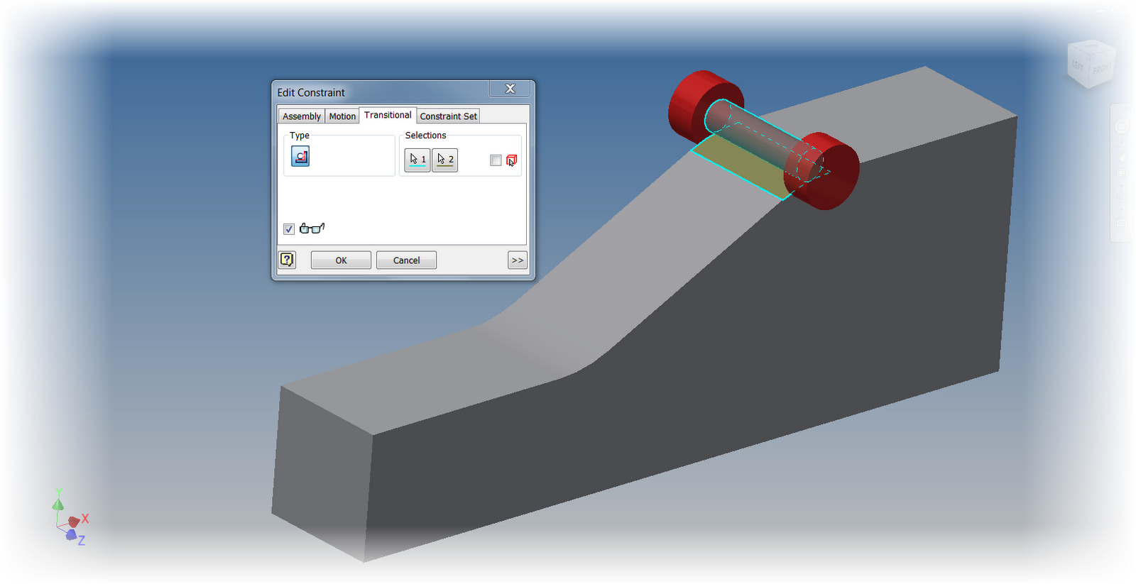
The Transition constraint being applied to a "Cam and Follower"
Looking at the image above, it might make sense to use the Tangent constraint. It would seem perfect to hole the cam and follower together.
However, if this constraint is used, the tangency will only follow one face. It won't transition to another face like the follower would in the real world.
This is where the appropriately named Transition constraint comes into play. It can "see" the faces it need to transition to, and behave appropriately.
By using the Transition constraint. Inventor will allow the follow to "follow" the cam correctly.
Below is a video showing the behavior with the Tangent constraint, which isn't what I want, then I'll show the behavior with the Transition constraint, where we get to give the "big ol' nod of approval"!
Last week, I was talking to someone about how to best represent a spot weld in Autodesk Inventor.
The first observation to make is that Inventor has a Weldment environment that provides several tools to help with welding. It's got a variety of tools. It can separate the weldment into different sections, the assembled environment, the preparation environment, the welded environment, and finally machined environment.
This is a great tool if a high degree of detail is needed in creating a welded environment.
But what if just a simple representation is needed?
In the brainstorming session, an idea was brought up.
What about creating a sketch in the assembly, showing the spot welds in the sketch, then showing it on the drawing?
The sketch added to the model
The sketch added to the drawing
I tried it. It works! The sketch can be shown, annotations can be added and so on.
Here are the basic steps:
Create a sketch on the model (part or assembly)
Place the view in a drawing.
Right Click the Assembly in the Drawing Browser
Choose "Get Model Sketches"
And BOOM! That's it. It's pretty easy!
So keep this in mind for your designs. And keep it in mind for any application it can help in. I used spot welds in this example, but any place a sketch can help, use it!
Of course, here's a video showing the example I described!
One last thing. Do you have a place where this workflow helped you out? Share a comment and let me know!
Another plus, is the flow is pretty natural, at least in my humble opinion. The basic steps are:
Select the components to be added to the simplification by picking, or using a filter for external parts
Inventor Simplify creates a View representation containing the parts selected
Export the parts to an Inventor part file that now contains the simplified geometry. If desired, the exported geometry can be edited further by patching holes. This removes additional detail, or even voids.
.
Optionally, components can be reduced into "envelopes". In other words, show the volume the components occupy, without showing the actual component. Handy for removing that intellectual property you don't want to show!
Additionally, if components need to be removed from the simplification, the View Representation can be edited. This makes it a lot easier to make adjustments.
An example of a simplified component
As always, I've got a video where you can take a look at the process. If, after seeing the video, you can't wait to get your hands on it, you can download it at the link here.
Have thoughts or cool uses for Inventor Simplfication? Throw out a comment.
On a more personal note. I've tried removing the "bookend" slides from the video. I'm looking for a little feed back on if the users out there would like them better "out" or "in". Let me know!
Many of us have been there before. We need to send our 3D CAD assembly to a 3rd party, like a vendor, for example. But we don't want to directly export the full 3D model.
Why? The 3D model contains all the information required to build the components within the assembly. The "feature rich" assembly may be overkill because the extra information, such as internal cavities, may create a model that is "overly heavy and complicated" for the end user.
Even worse, giving them that feature rich model may give away proprietary information that may allow an unscrupulus end user to take advantage of our hard work.
Would you always want to send out a model with all this detail to a 3rd party>?
In older versions of Autodesk Inventor, you could derive the assembly into a part model, and use standard Inventor part modeling tools to remove the excess features. You could even use Autodesk Inventor Fusion if you wanted.
But this process took time, and while it might be worth it to protect intellectual property, who doesn't want a faster way.
As of Autodesk Inventor 2013, there is a way.
To take advantage of this new tool, the model is still derived into a part file using the Derived Component too, just like before.
We still go into Derived Component
We can still go into the Options tab, and change how the assembly is derived and remove parts and features that we don't need.
But now check out the "Options" tab for the new options.
But a new option in this window is to remove internal voids that allow the part to be quickly simplified. With the addition of this tool, manually filling holes, voids, and generally "dumbing down" an assembly can be reduced, or even eliminated.
Remove voids! The new tool!
So on that note, here's a video that shows both the steps, and the result of a quick simplification of a component.
Have a suggestion on how you approach this challenge? Drop a comment below!
A new change in Autodesk Inventor 2013 is how materials and colors are handled. Instead of being a part of the Styles and Standards libraries, like in previous versions of Inventor. Now, they're stored in Appearance Libriares (for colors), and Material Libraries (for materials).
The location of the new libraries can be seen by looking at the project file.
The libraries as shown in the Project File
But what if there are old libraries that have been created over time? We wouldn't want to throw them out and start over right. So there has to be a way to migrate them, right?
Well, of course there is! (or else I wouldn't have anything to blog about).
But how are the libraries migrated?
It's fairly simple, once you know where to look, as I'm so fond of saying,
There are two places to access the Appearance and Materials Libraries.
The first is from the quick access toolbars.
The second, off the Tools Ribbon on the Materials and Appearance Panel.
On the Tools Ribbon
Choosing either icon will bring up the browser for that particular library.
Migrating to both the Material and Appearance Libraries is a matter of clicking on the "gear" icon in the lower left hand selecting "Migrate Inventor Styles".
The dialog for Materials. The Appearance dialog is nearly identical.
The source (the library to be migrated) is selected, followed by the destination library.
However, there are two destinations to send your migrated folder, one is to create a new library, the other, select an existing library.
So what to do?
There's two theories. One is to migrate your old libraries to a newly created one, and remove the old Inventor libraries. This makes sure you have "one truth" for those materials.
The other, is to merge them into the existing library. The important, custom materials will be there.
Which did I choose? Personally I used "Create New Library. For me, it was a little easier to have that "one version" of the truth. I can remove one library later if I don't want it.
Hit okay, and the migration begins.
Soon, the migrated Material Library is complete.
The best part now, migrating the Color Library to the Appearance Library. Why is it so good? It's basically the same steps! If you've done the Material Library, you can do the Appearance Library.
Naturally, it wouldn't be a blog post without a video. So here we go!
Do you have input on how you might have migrated your own libraries! Throw a comment below!


 y
y


