Find us on Google+ Inventor Tales: New Inventor Technology
Showing posts with label New Inventor Technology. Show all posts

Sunday, June 22, 2014

New in Autodesk Inventor 2015 - Enhancements to the "Look At" Tool

Look back, and smile on perils past.
Walter Scott

Autodesk Inventor 2015 has several enhancements, and some, like Freeform Modeling and Direct Editing are just plain cool.  There are several great links and videos on the subject, and while I have plans to show some of that functionality when time permits, I often like to show some of the functions that aren't as flashy, but I know users will tend to use all the time.

One of those new functionalities is the enhanced "Look At" behavior.  Which as I've used it, I think is going to be helpful as I wade deeper into Inventor 2015.

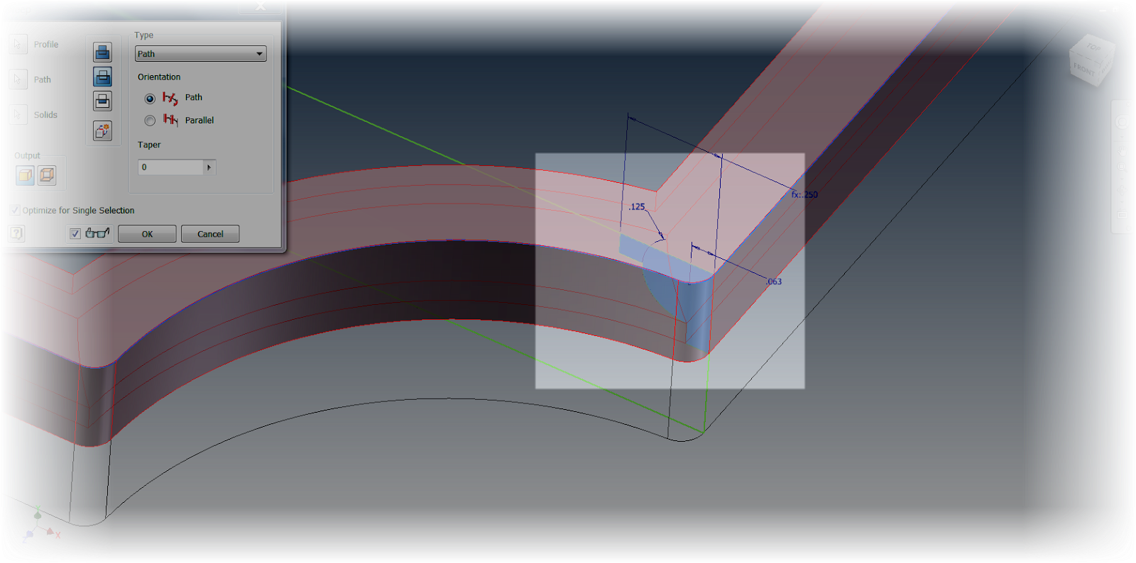
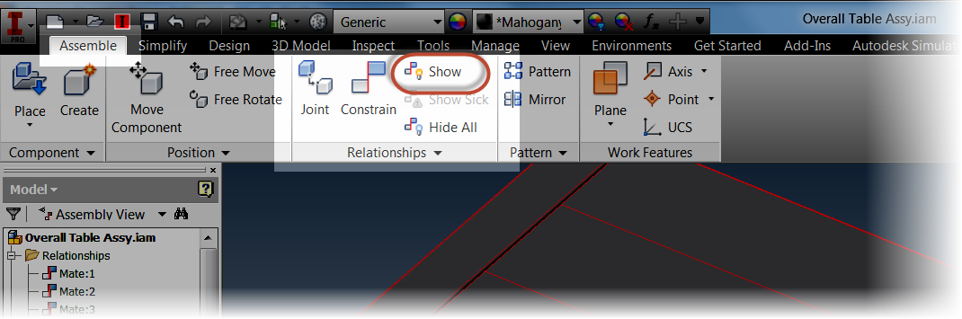
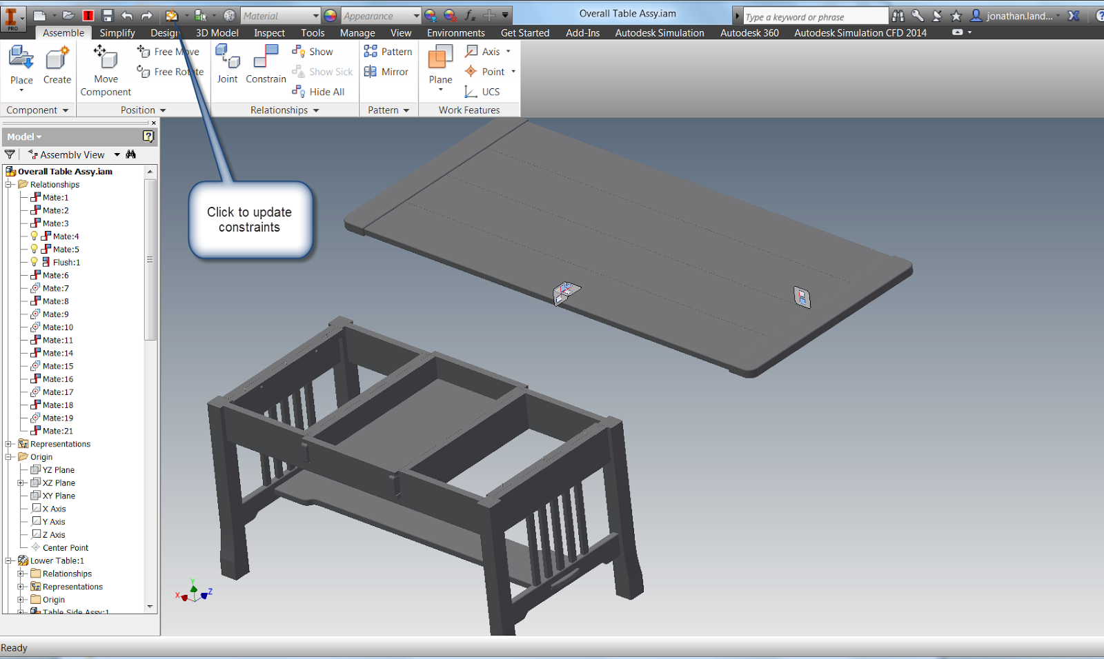
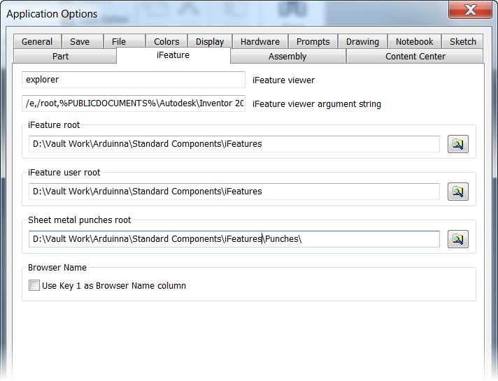
First, I'm going to show some new check boxes that are located in Tools>Application Options>Display Tab.

They're called, "Perform Minimum Rotation" and "Align with Local Coordinate System", and they perform the following functions (referenced from the Inventor 2015 help) :

If you want to use these new commands, make sure they're checked.

1) Perform Minimum Rotation - Rotates a minimum angle to make the sketch plane parallel with the screen, and the x axis of the sketch coordinate system either horizontal or vertical

2) Align with Local Coordinate System - Orients the x axis of the sketch coordinate system to be horizontal and right positive, and the y axis to be vertical and up positive.

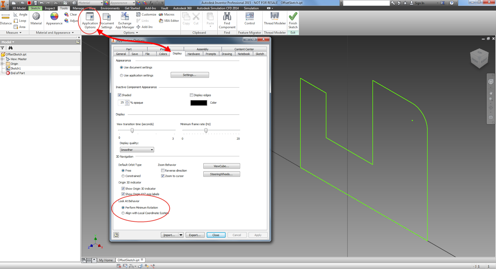
The location of the new settings

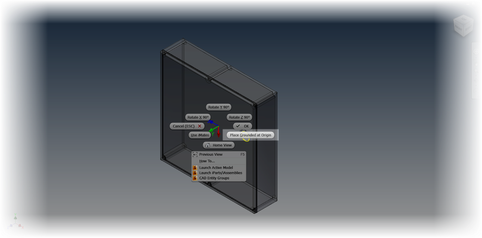
So in a nutshell, what do these new functions do?  First, a little history. 

For those of us who use Inventor in the past, we've all likely used the "Look At" command and watch our sketches to an acrobatic act before ending up in a position that we really didn't expect, or sometimes want.  

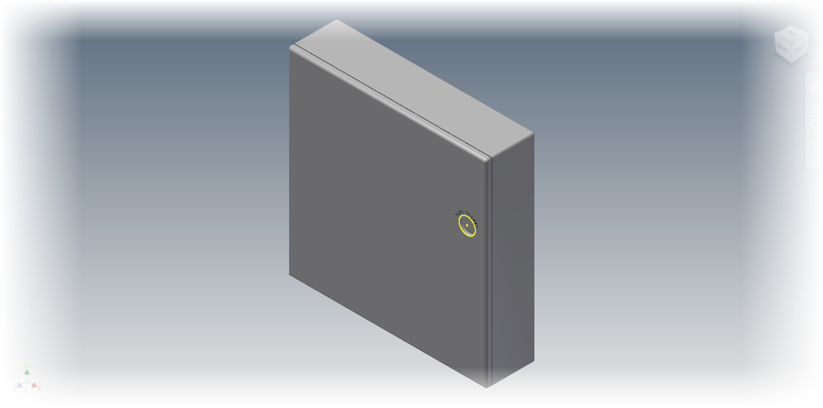
These commands work together to help prevent that.  The "Perform Minimum Rotation" option will prevent the "tumbling" we see in the ghosts of sketches past.  The "Align with Local Coordinate System" option will control the orientation of the sketch, and ensure that the sketches orientation is predictable. 

I've used these settings since I've started using Inventor 2015.  So far, I'm liking what I see. 

So if you're new to Inventor 2015, take a note of these settings.  More importantly, give them a try!  And give them a try in different combinations of one checked on, and the other off, you may find a particular combination that you like!

And one bonus trick!  Did you know a new feature for Inventor 2015 is the ability to resize the Application Options Dialog box?  Maybe not huge, but it's always been something I've been wishing for!  
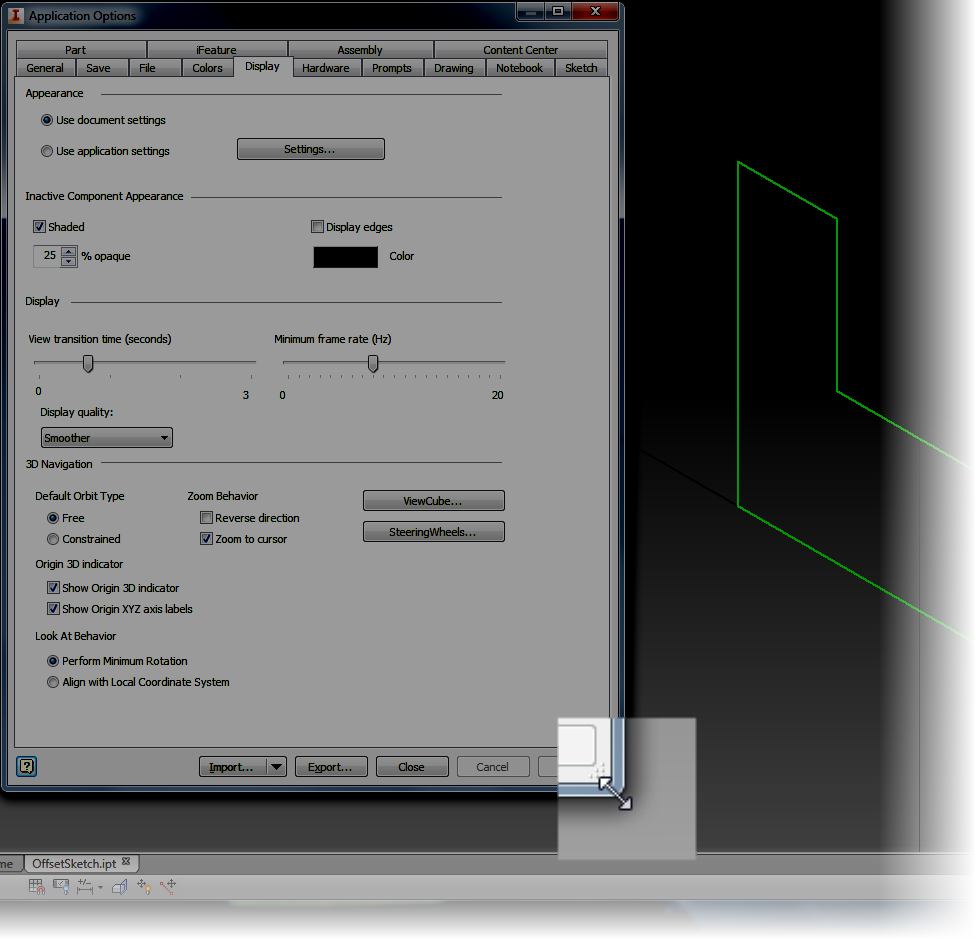

A nice new feature! 


Wednesday, June 18, 2014

Splitting Tables and Moving to Different Drawing Sheets - New In Autodesk Inventor 2015

“A table, a chair, a bowl of fruit and a violin; what else does a man need to be happy.”
 Albert Einstein

It's been a busy few weeks.  I've traveled to Michigan, taught Inventor classes, and even put my head into a Vault server once or twice.

Finally, I find a little time to talk about a new feature in Autodesk Inventor 2015.

This one is quick, and it's simple.

Moving a split table, such as a parts list, from on drawing sheet to another.

It's subtle, but it's a significant new feature that several users may find helpful.

In my example, I'm going to use the parts list table shown below.  It's crowding my drawing a bit, so I'm going to split it, and move one end of it to another sheet.

An example of my sheet as it looks now!
First, I right click on the cell where I want to split the table, and choose Table>Split Table

Splitting up my table
The table will split, and I can drag the parts list into two different locations.


But what I really want to do, is drag the template to a completely different drawing sheet.  For this, I need to switch to the drawing browser.  When I expand it, I can locate the Parts List, and see where it's split into two separate items.

The two halves of my part list

Now, all that's left to do is drag the parts list from one drawing sheet, to the other.  However, do this in the browser!  This will make sure it works correctly!

Drag and drop the sheet from one sheet to another


Once that's done, one half of the Parts List will reside on one sheet, the other half on the other sheet.  The icon even indicates this, as well as which sheet holds the original!

The sheet shown in it's destination.
The sheets shown together
So there it is!  A nice new feature in Autodesk Inventor 2015!  Take a look, give it a try with all the table types!  It works with everything I've tried, except the revision table!

And feel free to throw a comment below!

And one last note!  For the full list of What's New in Autodesk Inventor 2015, check out think link!

Wednesday, April 16, 2014

It's That Time of the Year Again! What's New in Autodesk Inventor 2015

“When patterns are broken, new worlds emerge.”
Anonymous 

It's an exciting time of year for Autodesk Inventor geeks!  Surfing around the internet, I found my first "What's New" video for Autodesk Inventor 2015!

I'm really looking forward to getting into the free form technology that was just added!  It looks powerful, very powerful indeed!

But, why not talk a look at the video from Autodesk below!  Take it straight from the source and see what you think!

Tuesday, October 01, 2013

Cutting the Wire - Introducing the Space Mouse Wireless

“Many a live wire would be a dead one except for his connections”
Wilson Mizner

I've been a fan of 3DConnexion Devices since I first used one in Autodesk R10.

That's right, not 2010, Release 10.  That puts that around 2005 or so. 

A while, in other words.

I've gone through a SpaceTraveler, which they don't even make anymore, and I now alternate between a SpacePilot Pro and a SpaceMouse Pro.

And now, a new member joins the 3DConnexion family.  The SpaceMouse Wireless.

Courtesy of the 3DConnexion website


I've been told a few times "Why don't they make a wireless one?" 

Apparently I 3DConnexion was listening.  And now it's here! 

Check it out on the 3DConnexion Website here! 

I'm excited!


Sunday, August 18, 2013

Migrating Assembly Level Features to Parts in Autodesk Inventor with a Neat Little Utility

It was exactly an assembly line. You could look into infinity down these rows of drawing tables.
Gil Kane

I hope it doesn't become too much of a habit.  But travels have again taken me away from my video gear, so I'm not able to provide a video again this week. 

But below is a post sans video.  Fingers crossed I can add one soon!

The Autodesk Exchange Apps website is an Autodesk Inventor tool that I think doesn't get the press it deserves.

The Inventor App Site


Much like the application stores most of us have used for our mobile devices, the Autodesk version has utilities for many Autodesk programs, such as AutoCAD, Autodesk Inventor, and Autodesk Vault.

The reason I've decided to talk about this site is that I found a nice little utility I liked, one that I'll definitely be saving for the future. 

It's called "Inventor FeatureMigrator", and it's what it does that makes it interesting.

It can take an assembly level feature, and transfer it down to a the parts that the assembly level feature passes through. 

The Feature Migrator on the screen

I've been asked if there's a way to do this many times, and the answer has always been "no".  Now, with this little free utility, it's not! 

The first thing I did was download it from the site, and install it by clicking on the downloaded file.


Downloading the app.

Once the app is installed, I'm ready to use it.  Here, I'm using an assembly of three components, with a slot placed through all three of them using an assembly level feature.

Three components with an assembly level slot punched through them


At the moment, Inventor looks much like it always has. 

But, once installed, Inventor FeatureMigrator adds a button to the Tool Ribbon in the assembly file.  


Finding the tool.

Clicking on this button starts the tool, which appears as a browser style window inside Inventor.

The "Browser Window"


Here I can see the assembly level features that are applied to this model, in this case, it's just a single feature I've named "Slot".

To start the process,  I right click on the feature I want, and choose "Send to Parts". 

Sending the features to parts

A dialog box will appear that has options for what to do with the translated assembly level features, such as options for suppression or deletion.  There are also options for how to handle "non-healthy" part features, even what render style to use on the part features.

The Translation Report

I can also click on the "Detailed Report" button to see more info on the translation.

The Detailed Report

Hitting OK will complete the process.  The Slot I created at the assembly level is now pushed down to the part level.  To confirm this, each part can be opened and checked.


There are a couple of interesting quirks, in this little utility.  They don't bother me, but it wouldn't be right for me not to mention them.

1) It creates new copies of the components it affects, adding a "_1" to the filename.  I presume this is to make sure that sweeping modifications when a part use across multiple assemblies is modified. 

2) The sketches it creates aren't fully constrained to the new geometry.  So it may be beneficial to constrain (or fix), the geometry in each part.

For me, these are things are just curiosities for the advantages I gain, but I leave it for each user to decided.  If you think this tool is useful, Swing by the Autodesk Exchange App website and take a look!

I also like the Feature Recognition and Thread Modeler apps, so feel free to take a look at those too! 


Sunday, July 28, 2013

An Introduction to Autodesk Configurator 360

You're giving a gift, so finish that process. If you configure it for them, your sweat is in it.”
Alfred Huger

Back on July 9th, 2013, Autodesk announced Autodesk Configurator 360.  It's a cloud based configurator where Autodesk Inventor files can be hosted and configured given parameters and iLogic rules online. 

All that's required is to upload a model to Configurator 360, select the desired options, and release it into the wild.  There are even options to control who can access the configuration.

So with all this cool stuff, how is Configurator 360 accessed?

First, you need something that can be configured.  In this example, I'm using an assembly powered by iLogic.

This is a template for a router jig for use in wood working.  This is a template that can be copied, then modified to fit the part it's going to cut.  The iLogic rules drive the size of the base, and the position of the handles and stop on the base.


The router jig template, showing the iLogic form that drives it.


Next,   access to the Configurator 360 site is needed, which isn't difficult, a 90 day trial can be obtained here. 


The Configurator 360 site

Once a trial is obtained, I can go ahead and log into Configurator 360 site, I'm going to take this folder, in a zipped format and upload it to my Configurator 360 site.

I upload my design by choosing the Designs tab, and clicking the New Design icon.

Adding a new design to Configurator 360


The screen to upload the file will appear. I'll have the option to name the project, choose a format to upload the files in (*.iam, zipped *.iam, ipt, or zipped ETO). 

Adding an assembly to Configurator 360

Now, all I have to do is click the upload icon to upload the file to Configurator 360. Note that at first, the webpage may have to be refreshed to get the files to appear.


Once the webpage is refreshed, the Configuration appears, and it can now be edited by selecting the icon in the picture below. 


The first tab that appears is the "Access" tab.  This tab provides a place to change the display name, create a description, and control access permissions to this particular configuration.


Clicking on the Parameters tab, options to control parameter name, order, and if a parameter is read only or not can be set here.  Here, parameters can be set to read only, or minimum or maximum values can be set.


Now, that this is accomplished, I can make the configuration available. for users, where they can change, values, and download files as needed, to make use of the configuration that has been provided to them via Autodesk Configurator 360.


So have a look at the configuration I created at the link here, and see for yourself if something like this might be helpful to your business..

If it is, have a go at the free trial on the Configurator 360 site!

And take a look at the video below!


Thursday, July 11, 2013

Autodesk Configurator 360 - Something new from Autodesk

“You're giving a gift, so finish that process. If you configure it for them, your sweat is in it.”
Alfred Huger

Today, it's just time to talk about something from the news desk. 

As of yesterday, Autodesk has released Autodesk Configurator 360

This cloud application allows the user to upload Autodesk Inventor components, select key parameters, and let someone, such as a customer, configure the components via a cloud application. 

It's brand spanking new, so new it's still got that "New Software Smell".  So I can't say that I know all of it's ins and outs.  But here's a video to take a look at. 


It comes with a 90 day trial, so it might just be worth taking a look at! 


Thursday, June 27, 2013

Released into the "Wild" Autodesk Fusion 360 is Here!

“Fusion will be the final way out for the future.”
Shen Wenquan

Earlier this week, Autodesk announced Autodesk Fusion 360, a cloud based mechanical design tool.

So what does this exactly mean? 

Instead of a heavy 3D modeller sitting on top of your workstation, now you're operating on the cloud. 

The files are stored in the cloud.  In that ethereal world of 1's and 0's, designs are shared, collaborated upon, and versions are tracked, the whole time the design is being created, or "ideated",to use the popular buzzword

In this respect, it reminds me a bit of how I've been storing documents on Google Drive for years.

There's also a nice dashboard where projects can be managed with the design team of other Fusion 360 users.  Combining a bit of a social media site with data storage for design files.

Files can be accessed where ever you have access to your Autodesk Fusion Account, and since the files are on the cloud, they're also accessible, as well as continuously being backed up. 
No more opening your laptop to realize you forgot to copy a file from the server! 

Just yesterday I signed up for my Fusion 360 account.  I'll shortly start creating simple parts, trying some collaboration, and quite simply, kicking the tires on a new way of approaching design.

Here's my new dashboard.  A clean slate ready to get started

So in many ways, I'm still learning about Fusion 360, and I expect to continue learning.  I'm hacking my way with my virtual machete, bullwhip on my hip and fedora on my head, trying to blaze my own new trail into new territory.

I'll be sure to let you know what I find!


And if you're interested in taking a look at Autodesk Fusion 360 yourself, click here to get started!

For more information on Fusion 360, check out the overview below from the Autodesk Fusion 360 team! 


There is also an interesting interview with Autodesk CEO Carl Bass with Bloomberg, where he discusses the cloud, Fusion 360, and even the U.S. Patent System.


Sunday, June 09, 2013

A What's New in Autodesk Inventor 2014 - Creating Self Intersecting Sweeps.

“The stream of time sweeps away errors, and leaves the truth for the inheritance of humanity”
Georg Brandes

I have some friends visiting in from out of town this week, so because of well spent time with them, this blog post is short, and without video.  I hope that it is still a helpful tip, even though it is quite brief.

In the last few weeks, I've been looking through the what's new topics, and seeing what I like. 

One of the tools that for my part, I think is going to be really helpful is the self intersecting sweep.

A self intersecting sweep is a swept feature where the profile intersects itself.  In earlier versions of Inventor, this sweep would be able to solve.  It would error out and fail.

An example of a sweep that would intersect and fail.

This meant readjusting the profile to make sure it didn't intersect.  And while, at least for my part, this hasn't been time consuming to do in the past, there's no beating not having to adjust the sketch at all.

This is where the new Feature in Autodesk Inventor 2014 helps out.  As a matter of fact, it helps out a lot.  It will allow this self intersecting sketch to calculate, and create itself without erroring out. 

A closeup of a radius that would have caused a failure in previous releases of Inventor.
But now, if I accept and hit "OK", Inventor calculates, and creates this sweep without a problem.  How about that!

Ta Daaaa!

I know that for certain profiles I would use, like router profiles in my woodshop projects, this is going to be a nice feature.  I can make sure that the profile matches the same profile my router bits will give me, without worrying about features that can't be swept because of that.

A view of the entire sweep profile

So think about this feature as you move forward into Inventor 2014.  Think of where it can be used for the type of sweep that router profile, where the result is legitimate, but it might not be easy to create because of the profile intersecting.


Think about it because, in fact, it just got a lot easier!


Sunday, June 02, 2013

Controlling Orientation of a Placed Component in Autodesk Inventor 2014

Future orientation is combined with a notion and expectation of progress, and nothing is impossible.
Alan Dundes

There are times when a component is placed in Autodesk Inventor, it doesn't take the orientation I want it to. It lays on it's side, back, etc.  Every way but the way I want it. 

Inventor can work with this just fine, but ultimately, I like my components sitting in a "natural" state.

Usually, I'll just unground the component, and assembly it to origin planes.  It took little time, and got what I wanted.

But now, 2014 has added a new option, the ability to reorient a component during placement.

  • Let's start with an assembly, where I'm placing a metal container with the Place Component command.  Notice that the container is laying on it's back.  I want it placed on it's bottom, like it would be hanging on a wall. 
    • It's important to note in the image below, that I'm still looking at the preview.  I haven't placed the component by left clicking yet.

The initial preview of the component placement.
  • Now, with the preview on screen, I right click to see the rotation options.  There are options to rotate around the X, Y, and Z axis in 90 degree increments.

Right clicking to see the rotation options.


  • In this example, I've rotated round the X-Axis once, and Y-Axis three times.  (It's a little like a combo on a game console!)


The corrected orientation

  • Finally, the component can be placed by left clicking or by right clicking and choosing Place Grounded at Origin

Placing at Origin
  • And that's all there is to it!  The component is placed and ground, all in the orientation I want!

The component placed!

And below, here's the video portion of the post!  I hope you find it helpful!

Sunday, May 26, 2013

A Tour of Constraint Relationships in Autodesk Inventor 2014

“Let's think of new opportunities, not past constraints, as we visualize the future of the state that we call home.”
Kathleen Sebelius

Sitting in my hotel room on a business trip to Dallas, Texas, I found myself taking a look at a new feature in Autodesk Inventor 2014, and thought I would go ahead and create a short post on it.

This new feature is "Show Relationship" in an assembly. 

Activating this feature shows the relationships between constraints in the modeling window, in a graphical format.

For this example, I'll use the Craftsman style coffee table I've used dozens of time before.


The constraint relationship glyphs showing on the Craftsman Style Table


By using a graphical representation, the constraint can be easier to visualize, modify, and delete.

The first step to using the relationship is to show them.  This is located on the Assemble Tab by clicking the Show icon.

The Show Relationships tool


Once the icon is selected, I can choose the components I want to show the relationships for.  In this case, I'm just going to look at the table top.

Glyphs will appear where the constraints between the table top and the lower table it's connected to.

The Constraint Relationship glyphs

Right clicking on the constraint glyphs provides the operations that can be performed on this constraint, such as, Edit, Delete, and Suppress, among more.

Right clicking on a glyph will show the editing tools


If the component is moved using the Free Move command, "bands" appear that connect the constraint to its mating components while the command is active.  After this I can right click and choose "OK" to complete the move.

Using the Free Move command to separate components


Clicking on the constraint will also highlight the geometry that the constraint is attached to, giving a quick graphical way of seeing how the constraint is being used to constrain the geometry.  Just like before, right clicking on a constraint will show the options for that constraint

The components move apart, showing the right click options

Updating the assembly will update the constraints and return the component to its original position.


Updating the assembly will restore the constraints

But before I say "take this tool for a spin", there is on other place this tool can help out.

If there are "sick" constraints, such as conflicting constraints, can be graphically diagnosed using the Show Sick Relationships tool.


Showing Sick Constraint Relationship for diagnostic purposes.

With this ability, the Show tool can be used for editing, and for diagnostics!

So on that note, take this tool for a spin!  And in addition, here's a video on the subject!


Sunday, May 12, 2013

Placing an iFeature from Autodesk Vault 2014 - New for 2014!

“Burglars know there's more than one way to skin a vault.”
James Chiles

Early this week, I had a chance to play with an intriguing new feature of Autodesk Vault 2014. 

It's the ability to add iFeatures to, and place iFeatures using Vault.

I'm going to definitely use this tool in my personal projects.  I've created plenty of features in my day, and many times, I recreate them because I'm careless and lose them, forget to migrate them, etc.  I can get creative when losing iFeatures.

Trust me!  No matter how many times I tell myself I'll be more careful, I've sent many an iFeature to the "Land of Lost Files"!  Vaulting iFeatures will definitely reduce lost iFeatures in the future.

But, is it set up to work with Vault? 

I don't claim to have all the tricks figure out.  I'm still trying some things out, but here's what I've discovered so far.  Take my ideas, modify them, tweak them, and use them for inspiration. 

The first thing I did, was choose a folder in my Vault Workspace to store my iFeatures.   I also copied my default iFeatures here, so I can use them if I want.


Why?  This will prevent this error, when trying to check in iFeatures from the default Inventor location!  This error is caused because the default iFeature location isn't located in the Vault Workgroup path.

This is an error.  Years of experience have taught me that errors are bad.
I'm also going to change Inventor's default iFeature location to match the workspace.  This will make sure that I'm always using the same iFeatures I've Vaulted, even if I don't place the iFeature directly from Vault.

First, I change the default iFeature location in Tools>Application Options>iFeature Tab.  Note that sheet metal punches are a special class of iFeature, so I'm going to change that location too.

The new locations specified in Inventor's application options
 Now, an iFeature can be checked in and out of Vault, and enjoy all the benefits of being stored in Vault!

Checking into Vault

Once it's checked into Vault, now it can be placed from Vault onto a part that needs it.

Placing an iFeature from Vault
And after that, it's just like an iFeature has been place for years!

And it's placed
And here's the video version of the process!


One thing I have noticed, is that this tool doesn't work with sheet metal punches.  So I've decided that I'll have punches Vaulted but keep them in my local workspace, using the settings I created above.  Maybe we'll see that one come in the next release!