Find us on Google+ Inventor Tales: General Inventor Topics
Showing posts with label General Inventor Topics. Show all posts

Monday, September 15, 2014

Five Quick Tips for Autodesk Inventor Part modeling


“He's been a part of the whole run.”
 Gary McNamara

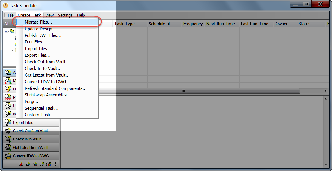
My last post, I talked about 5 tips that could be used in Autodesk Inventor Sketching.  Now, I've decided to go ahead and share a few tips in Autodesk Inventor part modeling that everyone may be aware of.

They're quick, they're simple, and they work for me.  I hope that the 'Verse out there can find a use for them too!

Just like before, the order doesn't imply a preference, just the order the popped into my head.

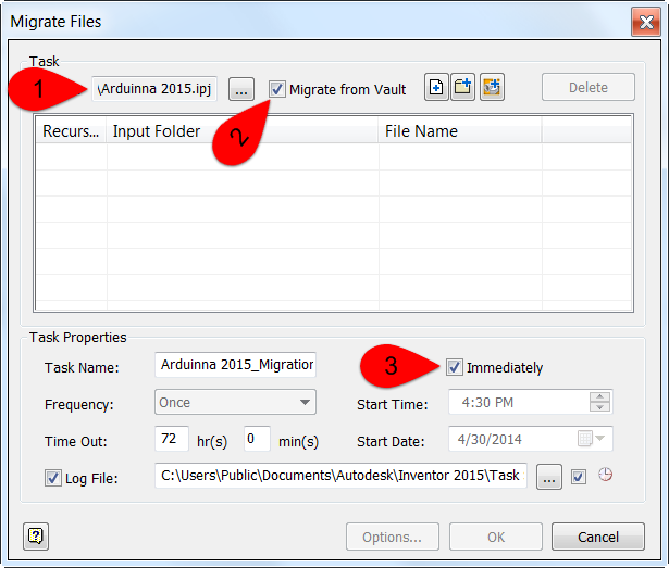
1. Create an offset workplane at the same time a sketch is created.  

It's a pretty common practice to create an offset workplane, then to follow that up with a sketch.  An example would be creating a boss that's being attached to a cylinder.

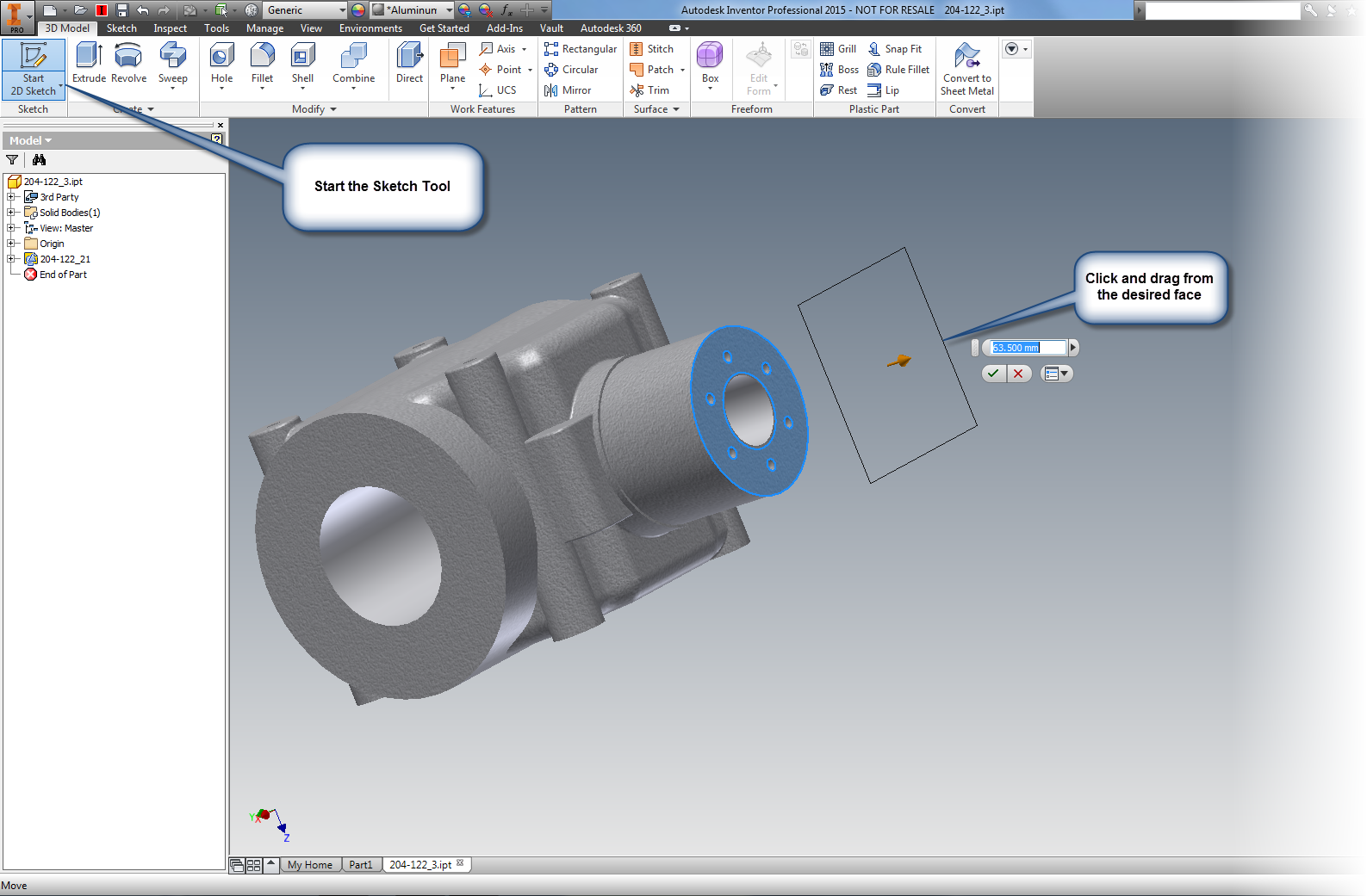
But did you know that you can create both the plane, and the sketch at the same time?  Here's how!

Start the sketch tool in which ever way you prefer.  Then much like you would create the offset workplane, drag the sketch.  The workplane and sketch will be created at the same time!


Dragging the sketch and workplane at the same time. 

The one sketch, one offset plane, one motion! 
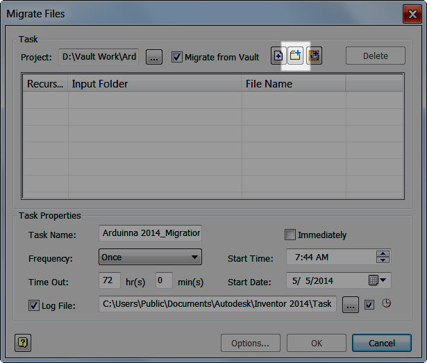
2. Select Other

I don't think this tool gets the credit it deserves.

In brief, if there are selectable objects stacked on top of each other, the select other tool will help you pick through the part, and select additional entities, even if they're not visible.  For example. the Select Other tool will let you pick the back face of a part.

One way of accessing the tool is to hover for 2 seconds over the desired selections.  The other is to right click over the desired selections and choose the tool from the right click menu.

The Select Other tool in action
PRO TIP!  The default "hover time" for the select other tool can be changed by going to Tools>Application Options.  The setting is located on the General Tab.

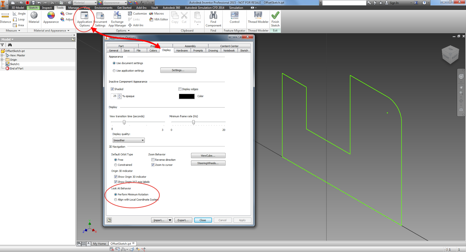
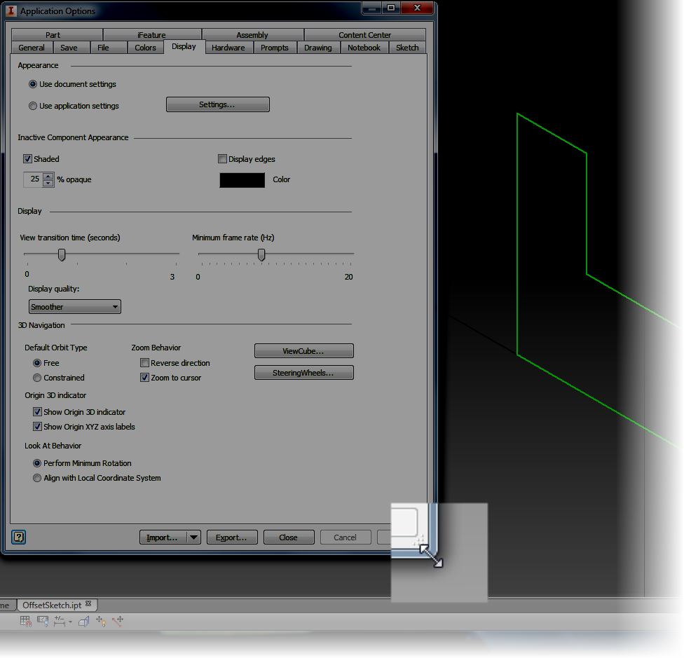
Changing the time it takes for the select other tool to appear


3. Sweep along an edge.

This function has been around for a few releases.  And that's the ability to use the Sweep tool along an edge. Once upon a time in Inventor, a second sketch was required to generate a swept path. Many may still be using it the way "it used to work" still do that.  However, it is possible to just use an existing edge instead of creating a whole new sketch.

Sweeping using an edge.  The edge is highlighted, but not selected yet. 


4. Create a four hole pattern using a sketch

Inventor has been able to create holes using sketches since I started in Release 4.  As a matter a fact, at one point it was the only way to do it.  And while it could be considered an older tool, it's still a very useful tool.

One place it can be used very effectively is to create a four hole pattern, such as mounting holes in a lid.

I like using this, instead of a pattern for one big reason.  I don't like doing math with the four hole pattern.  Call me lazy.  Using the offset tool allows the sketch to be offset with one dimension, and the offset will be maintained should the overall dimensions change.

In order to do this, create a sketch and offset it's perimeter using the offset tool.  Next, just finish the sketch, and start the hole tool.  All that's left to do is place a hole on each corner of the offset rectangle using the From Sketch option.  Choose the hole type and go!

Using an offset sketch to create a four hole pattern
5. Slice Graphics and Project Geometry.

This is two tips combined in one, but they often work in conjunction.  That's why I'm combining them.

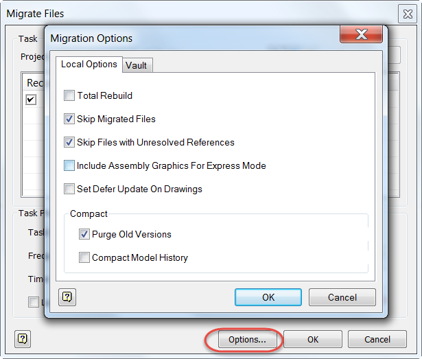
These tools are most often used when a feature needs to be created on the interior of a part, such as an O-ring groove inside a part.  Slice Graphics will virtually "cut" the part, while project geometry will project the edges cut by Slice Graphics so they can be used in the sketch.

To use Slice Graphics, start the sketch on the plane intersecting the part, and choose Slice Graphics (or hit the hotkey F7).

Once Slice Graphics is enabled, the model will be sliced at the sketch plane.  This is a virtual slice, like an XRay or MRI.  No material has actually been removed.

Next, click the Project Cut Geometry tool (it's on the flyout under Project Geometry), and select the model.  The edges of the virtual cut will be projected onto the sketch. Now that sketch can be used to create the geometry used to create the feature.

Slice graphics and project geometry already selected.  The icons are highlighted. 


So there are a few tips you can use when creating parts in Autodesk Inventor parts.  I hope that they're something you can start using right away.

******************Edit 23-September-2014 Added Video (Finally!)************************

At long last the promised video!  Take a look to see these tips in a video format!


Wednesday, August 27, 2014

Five Quick Tips for Autodesk Inventor Sketches

“You can't do sketches enough. Sketch everything and keep your curiosity fresh.”
 John Singer Sargent

A few weeks ago, I found myself training an Autodesk Inventor course.  As with any class, I always try to throw in a few of the "simple" tips.  They're the little things, but things that can be used every day, in just about every Inventor session that lasts more than a few minutes.

So as I thought about this post, I thought I'd collect a few of the common tips for different aspects of Inventor.  And what better place to start, then at the beginning of nearly every Inventor part.

Why not start with sketches?

I won't get wordy on this one.  It's time to just go ahead and jump right in.  Here are five Inventor sketching tip. The order is random.  It's not a ranking.  It's just five tips that I like to use.

So here goes!

1. Temporarily turn off automatic constraints

Inventor will try to add constraints as you sketch, such has horizontal, vertical,  perpendicular, and parallel.  But sometimes, those constraints aren't wanted.

To turn off that functionality, hold down the Ctrl key.  Automatic constraints are turned off as long as the Ctrl key is held down!

That's my high mileage, very dirty Control key.

2. Change what geometry Inventor is automatically creating constraints between

When sketching, Inventor automatically creates constraints between the geometry being created, and existing geometry.  At times this can seem to be arbitrary.  But did you know that if you "scrub" the desired piece of geometry with your cursor, you can change what geometry Inventor is constraining to.  Just remember to rub the geometry with the mouse cursor, don't click!

First scrub the desired geometry

And enjoy the result! 


3. Creating an arc while still using the line tool.

I compare this Inventor function as being similar to AutoCAD's polyline function, which is creating an arc while still using the line command. This tool takes a certain "feel" and a dash of patience, but I think it's worth it.

When still in the line tool, click on the end of the line where the starting point of the arc is desired.  Now hold the mouse button down, and imagine your drawing the arc with your mouse cursor.  An arc will appear!

Creating a drag arc


As long as the mouse button is held down, the arc can be changed.  Dragging perpendicular to the line creates a perpendicular line, dragging in a tangent direction creates a tangent line.  Lifting the mouse places the arc.

Give it a try.  It may take a bit to get used to, but it's worth it!

4. Closing a sketch with a right click.

Another command that heralds back to AutoCAD's polyline functionality!  When ready to close out a loop of sketch geometry, right click.  In the right click menu, there's an option to Close.  Save a few clicks by letting Inventor close the sketch!

Close a loop of geometry


5. Restart a line without restarting the command!

There may be times when a continuous sketch may not be needed.  But that doesn't mean that the line command has to be completely exited and started over.  To create a line starting in a different location, right click, and choose Restart.  The line can be started elsewhere without restarting the command!

Restart without exiting the command
And to go with the tips above, here's a sketch tip to see those tips in action!

Friday, July 18, 2014

Showing Extended Names Inside of Autodesk Inventor's Browser

“Until he extends his circle of compassion to include all living things, man will not himself find peace.”
 Albert Schweitzer

Waaaaay back when in 2005, I bought myself my brand spanking new Chevy Colorado.  Since then, we've spent over 130,000 miles together.

Of course, the dealer made sure to point out the cool features the truck had when I was looking at it.

They pointed out the 6 CD changer, the power this, that and the other, the push button 4 wheel drive.  All features that I've come to appreciate in my loyal Ruby Red Chariot of Justice!

My 2005 Chevy Colorado
But sometimes there's that peculiar, but really nice, feature.  The one nobody thinks to mention. The one that ends up being that little thing that you come to appreciate having.

For my little Colorado, it's the "two position tailgate".  It's nothing more than an extra set of mounting hangars that allow the tailgate to rest partially open.

The stowed or standard "pick 'em up truck" position

The alternate "partially open" position

The standard open or "Party in the back" tailgate party position
It's simple, it's not flashy, but there have been times when I've needed an extra few inches in the bed, or when I don't want something resting flat in the bed, and this feature has been ideal when I've needed it.

Simple, effective.  I can appreciate that!

But I didn't start this post to brag about my 10 year old truck.

I'm posting because I want to post about a feature in Inventor that I would place in the same category as my two position tailgate.

It's called Show Extended Names, and what it does, is very useful, at least I think so!

First, I'm going to show what an Inventor Browser looks like by default.  This is it's as installed configuration.

The browser, in all its default glory
It's pretty nice.  It tells you what features were used to build the part, and in what order they were used in.  It gives a way to edit and change sketches and features and modify the parts.

But it can do even more.

To get to the "feature behind the curtain", I'm going to choose my browser filters, and make sure Show Extended Names is checked.

Changing the settings. 

Once this option is selected, look what happens!


More information is added.  Now I can see that an Extrude is a Join, Cut, and so on.  I can see the radius of a fillet, and the types of hole placed, among other things.

It's a simple thing, but something that's very effective.

So take a look at it, and see what you think!  For me at least, it was just like that two position tailgate, a nice little feature that I like making use of!

Sunday, June 22, 2014

New in Autodesk Inventor 2015 - Enhancements to the "Look At" Tool

Look back, and smile on perils past.
Walter Scott

Autodesk Inventor 2015 has several enhancements, and some, like Freeform Modeling and Direct Editing are just plain cool.  There are several great links and videos on the subject, and while I have plans to show some of that functionality when time permits, I often like to show some of the functions that aren't as flashy, but I know users will tend to use all the time.

One of those new functionalities is the enhanced "Look At" behavior.  Which as I've used it, I think is going to be helpful as I wade deeper into Inventor 2015.

First, I'm going to show some new check boxes that are located in Tools>Application Options>Display Tab.

They're called, "Perform Minimum Rotation" and "Align with Local Coordinate System", and they perform the following functions (referenced from the Inventor 2015 help) :

If you want to use these new commands, make sure they're checked.

1) Perform Minimum Rotation - Rotates a minimum angle to make the sketch plane parallel with the screen, and the x axis of the sketch coordinate system either horizontal or vertical

2) Align with Local Coordinate System - Orients the x axis of the sketch coordinate system to be horizontal and right positive, and the y axis to be vertical and up positive.

The location of the new settings

So in a nutshell, what do these new functions do?  First, a little history. 

For those of us who use Inventor in the past, we've all likely used the "Look At" command and watch our sketches to an acrobatic act before ending up in a position that we really didn't expect, or sometimes want.  

These commands work together to help prevent that.  The "Perform Minimum Rotation" option will prevent the "tumbling" we see in the ghosts of sketches past.  The "Align with Local Coordinate System" option will control the orientation of the sketch, and ensure that the sketches orientation is predictable. 

I've used these settings since I've started using Inventor 2015.  So far, I'm liking what I see. 

So if you're new to Inventor 2015, take a note of these settings.  More importantly, give them a try!  And give them a try in different combinations of one checked on, and the other off, you may find a particular combination that you like!

And one bonus trick!  Did you know a new feature for Inventor 2015 is the ability to resize the Application Options Dialog box?  Maybe not huge, but it's always been something I've been wishing for!  


A nice new feature! 


Friday, May 09, 2014

Getting Ready for Autodesk Inventor 2015 - Migrating Design Data

I have a sweet tooth for reading, so books migrate to my zip code en mass.
Dawn Olivieri

After installing your Autodesk Design Suite, migrating the Vault, and migrating Inventor templates, there's another migration to consider, at least with respect to Inventor

Migrating your Autodesk Inventor Design Data.

First of all, what does the Design Data include?  Design Data includes information such as drawing standards (balloon styles, dimension styles, etc), sheet metal bend tables, thread charts, and so on.

A sampled from my Design Data Directory

If you're running nothing but Inventor's defaults, then no migration is needed.

But seriously, who's doing that?  Nearly everyone has custom settings they need to migrate.

So this is how to go ahead and make that happen!

First, I like to make a backup of my Design Data.  Just in case I make a mistake, or something goes wrong.  This can be as simple as zipping up the design data and storing it in another location.

Make a backup.  You may not need it, but if you do need it, you won't regret it! 
Next, I can go to Windows Start>All Programs>Autodesk>Autodesk Inventor 2015>Tools>Style Library Manager.

Locating the Style Library Manager

Once the Style Library Manager opens, there will be two columns. One is for Style Library 1, the other, Style Library 2.


For Style Library 1 I'm going to browse to my 2014 Design Data (which is backed up, of course).  For Style Library 2, I choose the destination directory where I want to place my migrated 2015 Design Data.  At the moment, this directory is empty.

Notice that once I select the destination directory, the migrate button becomes available.


Now what?  I click the migrate button, and the styles begin their migration!  The Style Library Manager will tell me that the library will be migrated.  It'll also tell me I can't undo this!

But this is alright for two reasons.  One, I'm migrating to a new, empty directory.  The other?

I made a backup.  See?  I keep telling you there's a reason!


I click OK, and I now, I let the migration grind away.  Get coffee, watch YouTube videos.  Do both!

After a few minutes, the migration will complete.


Now, my custom libraries are ready to use!

I hope everyone finds this post helpful!


.


Monday, May 05, 2014

Getting Ready for Autodesk Inventor 2015 - Migrating Custom Templates

“Burglars know there's more than one way to skin a vault.”
James Chiles

In previous posts, I showed how to install your Autodesk Design Suite, as well as migrate a Vault from 2014 to 2015.

However, there are still things that need to be done.  For example, what about custom templates that have been carefully crafted in previous releases?  They aren't usable in Inventor 2015 until they've been migrated.

It goes without saying that this step is important.  So what are the steps to migrate template files?

The simplest, is to just open each template file in Inventor 2015 and save it.  It will work just fine, and it's a completely valid way of doing things.

However, I'm going to describe something that's more automatic then just opening and saving.

Here is my scenario.
  • My custom template files are checked into Vault
  • I want to check them out, migrate them, and check them in all in one fluid process


And while it's possible to perform these tasks manually, I'm going to use a tool called Task Scheduler.

Why?  I like letting the computer do the work where possible, and this is my chance!

The steps required for Task Scheduler are in reality, straightforward.  It's more a matter of knowing where to find the right tools.

Having said all that, what will Task Scheduler do for me?

It's going to check the files out of Vault, migrate them, and check them back in again.  Making sure they're all ready to use in 2015.

First, what are my preparation steps?  Really, there's only one.  But it's a big one!

Make sure everything is configured the way you want it.  For example, I'm still using 2014, so I've kept my 2014 templates safe and sound in a separate directory, so I can still use Inventor 2014.

Remember, once migrated, there's no going back!  So plan accordingly!

The first thing to do, is locate Task Scheduler, which can be found in:
Windows>Start>Autodesk>Inventor 2015>Tools>Task Scheduler


Once the Task Scheduler starts, choose Create Task>Migrate Files


Now, I see a screen to setup my migration.  There are several settings I can choose from.  For your migration, you can change any of the settings here.  For my migration for my vaulted, files, I'm going to make sure to check the following:

  • I'm going to choose my 2015 Inventor project
  • I'm going to check migrate from Vault
  • I'm going to start the migration instantly, instead of scheduling it for later (I'm impatient)


Now, I add the files from Vault.  The icons allow me to add Files, Folders, and an entire project.  I can even create combinations of these if it suits me!

But in my case, I'm just going to choose a single folder in Vault. This is the one with my custom templates.


After choosing the folder,  I'm going to choose my options icon, where I can change settings on what functions to use when checking in.

The first tab, the Local Options, such as rebuilding files, deferring updates, and so on.  The help system describes the steps well. In my case, I'm just going with the default settings.


On the Vault tab, I can add a Vizualization file, and delete the local copy from my workspace.

In my case, I'm not creating a visualization file, only because this is a template, and it's just a blank file.

I'm also not going to delete the local copy.  I need them locally to use them, so they have to stay!


Finally, I'm all ready to go, and I can hit the "OK" button, once to close the options, and once to "pull the trigger".

The migration begins, and all I have to do is give it a little time.


After a short time, it's done!  I have my new templates.


I can even double check by looking at the new versions created in Vault.


Now, my templates are all ready to use!

And for the video of the steps, take a look below!


Tuesday, April 22, 2014

Onward and upward! Installing Your Autodesk 2015 Design Suite!

We think a modern cloud lets you decide when you want to upgrade. We don't decide for you.
Larry Ellison

***********************EDIT April 22, 2014*******************************
Added video to accompany the text description
**********************************************************************


Ah. Software updates.  I'm always excited when the time comes to install my new Autodesk software.  There's new features to try, after all!

But as always, there are options that have to be selected.

So for this post, I'm going show the options that I use for install, as well as explain some of the other choices that might be used.

I can't cover every last detail, but perhaps what I can show can help you plan your own installation.

Before I start cranking, I should point out I'm installing from Factory Design Suite Ultimate 2015.  So if you're installing a different Autodesk software, some of the options may be different.

But even if you're not installing exactly the same product, there should be similarities!

1. To begin the install, click on Setup.exe to being running installer. 

The Setup.exe file.  Pulling the trigger on the installation.

2. This starts the installation.  Soon, the first installation screen appears.

Clicking the option to install to my laptop

For my configuration, I'm going to choose the Install option.  But here's a brief description of the other options.

Create Deployment: This option is used to create network deployments.  This is an install that's configured with a script.  It can be pulled to different users machines and make sure consistent settings are used for different machines.

Install Tools & Utilities: This contains the Network License Manager, CAD Manager Tools, and Vault Basic Server, among other tools

Choosing the Install option, I move onto the next screen.  This is the End User License Agreement (EULA). It's legal stuff.  You have to accept it.  'Nuff said.


The EULA.  Just say "Yes".  

3. After accepting the EULA and hitting next, it's time to choose the license type.

One choice is a Network License installation, where a server holds the license, and the installation "pings" the server for the license.

Since I'm installing on my laptop, I'm going to choose a Stand-Alone license. Also known as a Node Locked license, this will tie the license to the hardware on my laptop.

This screen is also where the serial number and product key are entered.  You'll get your serial number and product key from Autodesk.  (You can't have mine. Get your own!)

Note! Your 2015 Product Keys can be found at this link!

Choosing license type and entering serial numbers


4. Clicking next will now let me choose which programs to install.  I'm going to install the entire Suite.  But you could deselect any options an programs you don't want.  
The only thing I do on this screen is change my installation location, which I change from my C drive to my D drive (which is larger).

Changing my


Additionally, clicking on one of the programs will expand out additional options for the installations, such as downloading service packs (if available), and adding or removing certain components from the installation.

 Each one is different, so check the programs you're installing, and make sure the options you want are selected!


Make sure to click the program name to close up the options!  The install button will be grayed out until you do this!

5. this is all done, you're ready to Click install, and proceed! 


, For a video description, take a look below! 

Monday, April 21, 2014

A Guest VIdeo: Workflows for using Autodesk Inventor and 3dsMax Together!

“I see the computer as just another tool in the creative process, in place of or with paint, pencils or other drawing methods. Working digitally simplifies the workflow process.”
Donna Berger

It's been a busy week, and a busy (but wonderful) holiday weekend too!  I do have some 2015 blog posts and videos in the works, but things have been hectic!  So I'm still working on them!  I hope to have something up soon!

In the meantime, here's a great video from Marion Landry showing some tips and tricks on using Autodesk Inventor and Autodesk 3dsMax!  Take a look!  There are some nice tips in here!

Monday, March 31, 2014

Setting Component Materials Upon Import in Autodesk Inventor

“Finding the material wasn't a problem — remembering what to look for was.”
 Steven Severin

A question was posed to me earlier this week.  I'm importing files of different formats into Autodesk Inventor, but I need the material to be Mild Steel, instead of default.

Is that possible?

I wondered for a moment.  I looked around, and thought "what if I change the material in the standard.ipt template?"

It made sense.  Inventor starts with that template, what if the imported files made a pass through that template first?  There was only one thing left to do.


Try it! So the first thing I did was browse to the directory containing the standard.ipt template file, and open it directly. 


Make sure to open the file with the open command!  Do not create a new file from the template!  The material has to be changed in the template file, so when a new file is created from it, the material is already set.


Once the template file is open, it's time to choose.  In this case, I'm using Mild Steel.


Once it's the active material, I save the file and close it. 


Now that my template has Mild Steel set as the material, I can import the files that I need.  In the example here, I'm using Solidworks files that I've downloaded from GrabCAD at the link here.


The files will translate, and Inventor will now use the template to apply Mild Steel to the Imported Parts.

Checking the Bill of Materials screen in Inventor, I can see that indeed, all the materials are set to Mild Steel.


Now there are a couple of notes.

This option sets everything to Mild Steel.  Anything using this template will start with Mild Steel, so this may not be the perfect solution for everyone.

But it can be useful, and it's pretty quick to change.  So think about it, give it a try, and see what it can do for you!

And be sure to check out the video version below!