One of the new functions in Autodesk Inventor 2014 is creating a drawing view as a raster view, and allowing the user to make it precise at the time of their choosing.
For starters, what's the point of starting a view as a raster image, then making it precise later.
Simply put, it lets the user to defer the full calculation of drawing views until later. Imagine this on a large drawing view with a lot of calculations involved. Now extend that across multiple projected views. It can take quite a while!
Placing the views as raster views lets the user quickly place the views initially, then choose which views to make precise when needed. The "hit" on calculation can be spread out over time. Make one view precise, and work on it? Going to a meeting? Calculate another view while you're gone! Going to lunch? Make another view precise, and so on!
So that's the purpose of it! Now, how does it work.
When creating a base view on a drawing sheet, there's a check box to Raster Views Only. With this check box selected, the views will be placed quickly.
Checking the Raster Views Only checkbox
Aside from selecting that check box, placing views is the same. Once the views are placed, there will be green brackets around the views that are being represented as raster views.
Green brackets indicate these are raster views
At some point, however, it will become necessary to make the views precise. To do that, right click on the view, and choose Make View Precise.
Calculating the views into precise views.
The green brackets will disappear, and the view is now precise.
One view is precise now. The others can be calculated later, when needed.
Other views can be made precise later, when they're needed. The views don't have to be calculated at once!
And for a video description of the steps! Take a look below!
And for even more information on this tool, take a look at the Autodesk Online help video at the link here!
This weekend has been a busy one, so this weekend's blog post is a short one. But it's reflecting something that I've been thinking of doing for some time though.
File numbering schemes. Users spend hours and hours trying to figure out which one to use.
Is it better to use a sequential? One where the numbers have no meaning with regard to the files they're associated with?
Or is it better to create one where the file name has a meaning. A given portion of the file name tells the user this an assembly, or this component is made out of stainless steal, or is a custom part. The different meanings can go on forever, and are different from company to company.
In my own, personal file structure in Autodesk Vault, I've done what so many are guilty of doing. I've ignored it.
My own Vault file names are an example of what I'd tell someone not to do.
They have a mishmash of names. Most have some sort of meaning. Some are just names I threw in because I needed a name in a hurry.
Others are names that I changed with Vault's Rename command because I needed to make room for another file with the same name (I have "Enforce Unique File Names" checked).
An example of my similar, but not consistent file names.
I've wanted to clean that up. I would like more consistency in my file names. But I just haven't had the time or desire to create one.
So I decided to steal a number scheme from someone who's already created one. I'm going to use the one the FAA uses for their Air Worthiness Directives!
How does the FAA do it? They start with the year, then count which two week period in the year the document was issued. Then finally, number the documents in sequential order.
For example an Air Worthiness Directive numbered 2012-20-06 would mean the document was issued in the year 2012, in the 40th week of the year (20th two week period), and that it was the 6th document issued in that time.
I'm going to give it a try in my own Vault, and see how it works out! I'll use the file naming scheme, and for searching, I'm going to search for keywords and properties associated to the files.
An example of the properties I've added. I'll probably adjust them, but it's a start.
It will require discipline to make sure I fill out my properties, but it's something I should already be doing!
I'll keep you posted on how it goes. There will be benefits, there will be drawbacks. The real question is, which will outweigh which?
So what do you think? Are you a fan of meaningful, or non-meaningful file names?
In that post, there was a comment that stated once the sketches were made visible, the option to "Get Model Sketches" was grayed out. Which is true.
Get Model Sketches is now grayed out
So how can the visibility of sketches if they're added to the model after the "Get Model Sketches" option is used.
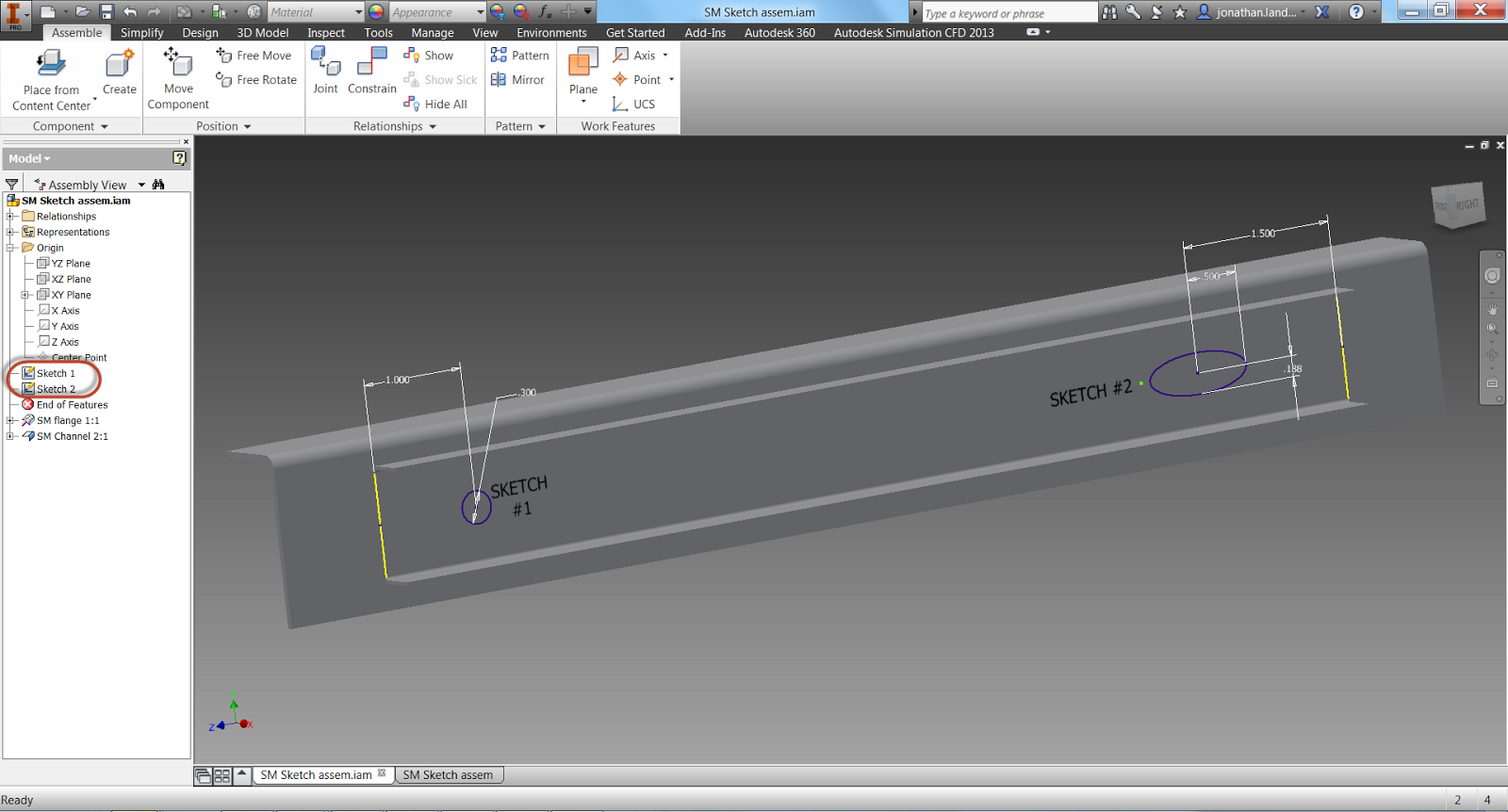
Here, I've added a second, distinct sketch in Autodesk Inventor 2014.
Note the sketches are separate
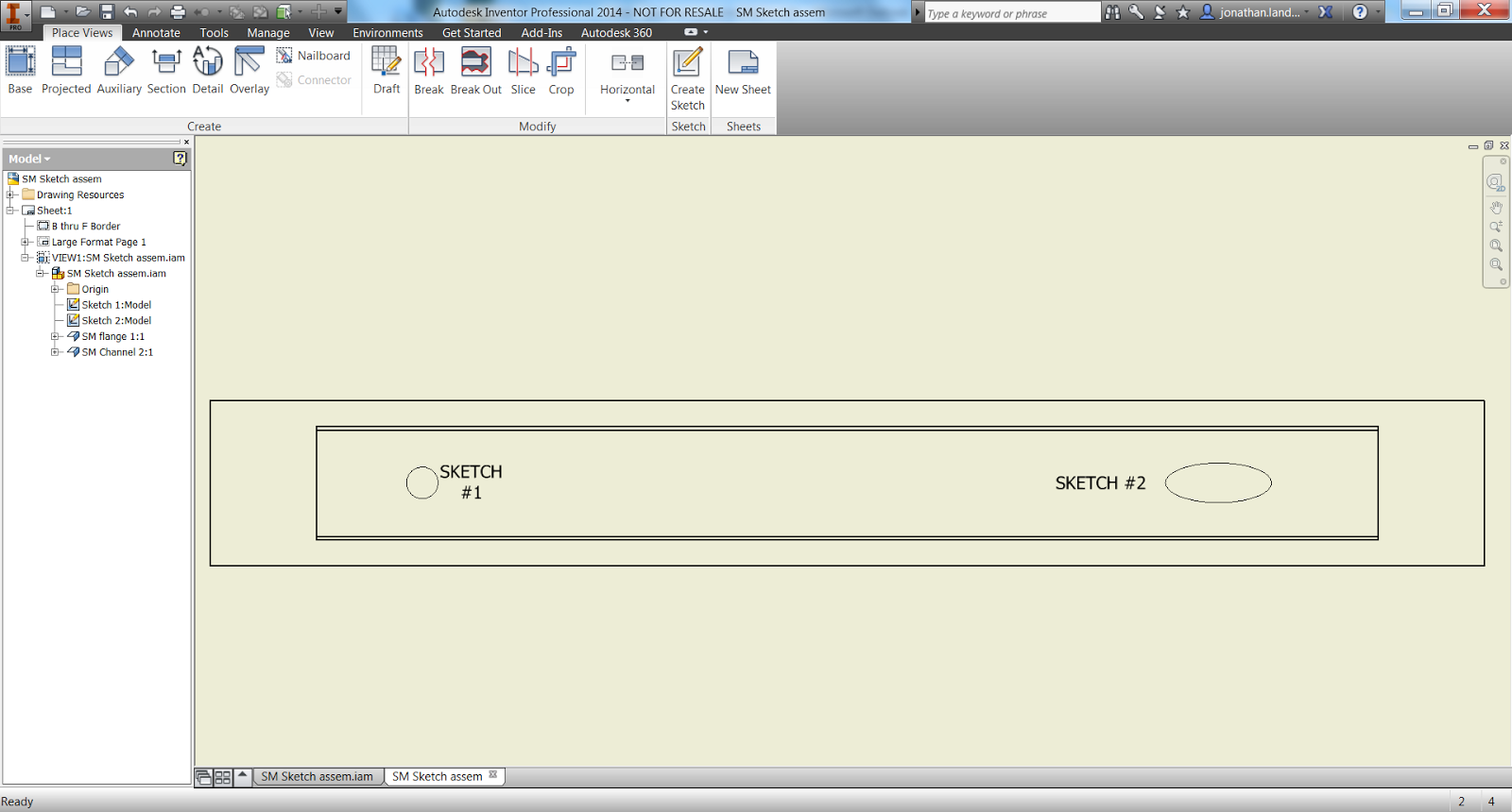
When I switch to the drawing, the sketch will automatically appear on the drawing, with no further interaction.
The second sketch appears
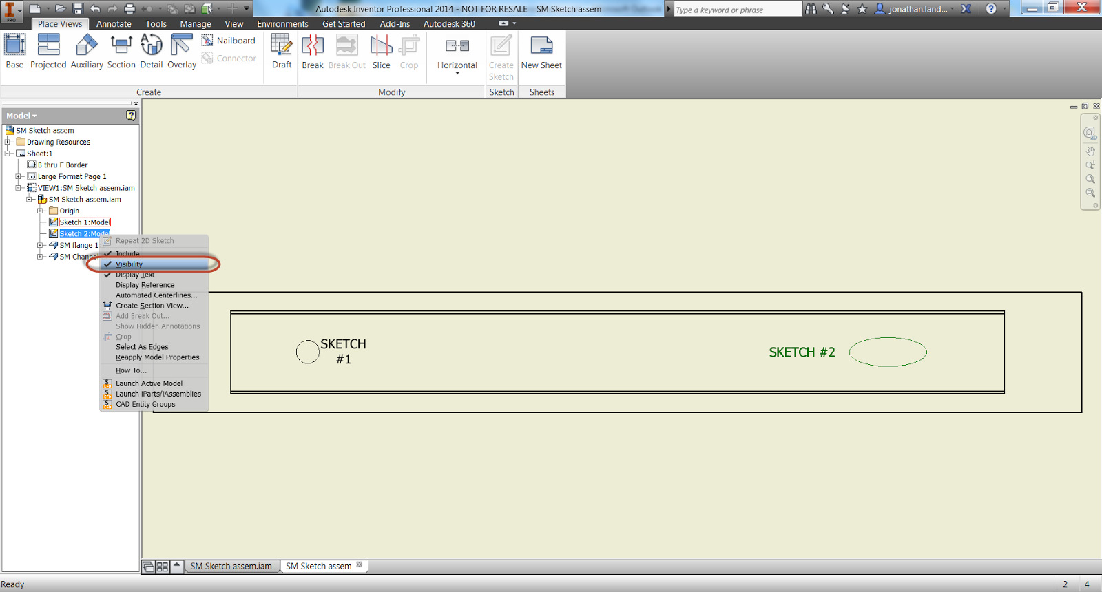
But what if I don't want to show both sketches. Perhaps one sketch represents a spot weld, and the other is just there for construction or a model only reference?
All that I have to do is right click on the sketch in the browser, and uncheck the "Visibility" option. The sketch will disappear and will no longer be shown. Showing the sketch will make the sketch visible again.
Now you see it!
Now you don't!
Being able to control the sketches individually adds more flexibility that an "all or nothing" approach. So take a look and see how you can use it!
In a previous post, I talked about migrating Styles from a previous release of Autodesk Inventor into Autodesk Inventor 2014.
The simplest way, of course, is just to open each file in Inventor and save it. This will migrate the files.
And it does have it's advantages. Opening the file would allow for an "inspection". Old styles could be inspected and purged, new styles can be added, and general clean up could be performed.
But another way to quickly migrate files would be to use Inventor's Task Scheduler. This tool allows for the templates (and any other file for that matter), to be migrated in batch, hands off.
Note! Before migrating any templates, make sure you've backed everything up! I've never had a problems with migration, but you only have to be wrong once!
To access Task Scheduler, go to Windows Start>All Programs>Autodesk Inventor 2014>Tools. Task Scheduler will be in there.
Finding Task Scheduler
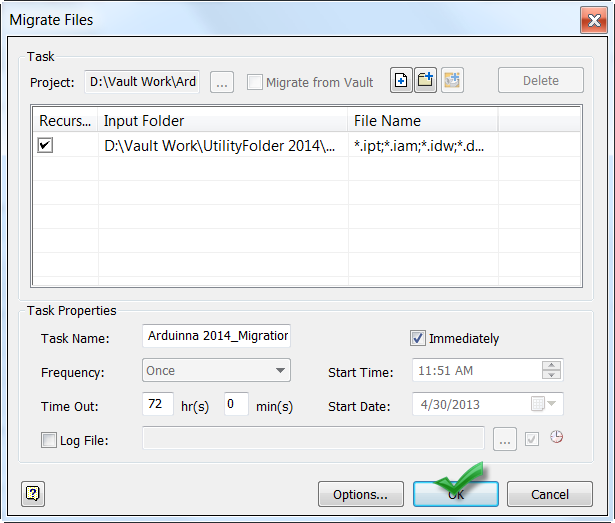
Selecting the icon will open Task Scheduler for use. Choosing Create Task>Migrate Files will bring up the dialog box to set up migration tasks.
With the Migrate Files dialog open, now the settings for migration can be configured.
There are several settings that can be changed for this dialog. Some of the major ones, and my preferences for this task
Project: The project under which the files will be migrated
Vault: Migrates the files out of Vault - Since my templates are not in Vault, I won't be using this setting
Folder icons: Are the files going to be added individually, are folders going to be added, or is an entire project going to be migrated? I'm going to use folders
Under Task properties, it's also possible to give the task a name (I just use default), and schedule the task for a given time. Since my templates aren't particularly large, I'm going to run them immediately.
The Migrate Files dialog.
In the dialog below, I've added the folder to migrate, and completed my settings. I also like to click on options, and have the Task Scheduler Skip Files with Unresolved References, Purge Old Versions, and Compact Model History.
If these were parts with features, I'd also compact the model history, but these are mostly empty templates.
Setting up options
Once the settings are ready, I can close the Migration Options, click OK, and start the migration.
Committing the migration
The migration will begin running. For templates, this typically takes a
few minutes, but it does depend on how many files are being migrated,
so that has to be taken into consideration before starting.
Once the notification is completed, right clicking on the task will allow for a report to be generated that will show which files were successful, and which files failed and why.
Finished!
But those are the steps to migrate files. Here I've used them in templates, but they're not limited to just template files. This is valid for any Inventor files, so remember that it's available for use!
If you prefer the video form, just take a look below!
But with that table placed into the drawing, there's an additional benefit I think makes this work flow worth considering.
When the Excel table is inserted onto the drawing, it maintains a link back to the Excel file, which make it what many like to refer to as "a single source of truth".
In other words, the Excel table can be updated, and all files looking at that table update as well.
Taking the example I used in my last blog post, I used Excel to create a chart that showed small tools and preferred vendors for a wood working project. I used it as a quick way of inserting standard information without recreating the table.
The Excel table used in my previous blog.
I've taken this particular table, and inserted it onto two different drawings, which will be using the same information, one is the Saturday table I used in last weeks blog, the other, a blanket chest for a different project.
The Saturday Table
The Blanket Chest
For this scenario, I'm going to say that Reed Wood Supply has been purchase by "Blue Sun" (who recognizes that movie reference?).
I'm going to stick with them as a vendor, and just swap "Reed Wood Supply" with "Blue Sun".
To do that, I open up my Excel table, and make the changes. I can do this in one of two ways.
The first is to just open the Excel table up by browsing to it from Excel, the other is to locate it's link in Inventor's browser, right click, and choose "Edit".
Browsing to the File in Excel
Right Click and Edit in Inventor's browser.
Either way, I can now modify the file and save it.
Changing to "Blue Sun"
Once saved, the tables will update to reflect the new changes in both drawings.
The updated table
I've noticed that when I right click and choose edit from the browser, the table may not refresh right away. If that happens, right click on the table, and choose, "Update" . After that, all should be as it should be.
Updating the table manually.
There is one other capability of this method I find intriguing If the table is edited like an Inventor Table, additional rows can be added to the table for a particular drawing. However, these rows that are added don't propagate back to the Excel table.
I like the thought of this because if a particular project uses mostly the same "common" table items, but has a few that are unique, I can stick them onto the end of the table, and getting the best of both worlds.
To accomplish these steps, right click on the table and choose edit.
Next, right click on the edge of the border, and choose "Insert Row".
Now enter the desired values and repeat as needed. In this example, a different finish is being used on the Saturday table, so I've added a finer grit sandpaper and spar varnish to the vendor list. Since the table was edited in Inventor this time, only the drawing where I made the edits is changed.
The rest remain the same, allowing me to keep common what I want to keep common, and add where I need to add.
The two tables compared to their Excel source. Notice the added items on the top table.
So that's it. Utilizing the Excel table as a single reference, and making edits to accomplish different results. I do like some of the things I see here, and I think I'll utilize this more in the future.
I hope you can to.
And to wrap this up, check out the video on this work flow below!
Last week I found myself working with tables in Autodesk Inventor drawings, and realized that I'd forgotten a nice little capability drawings have. Among being able to import tables and parameters from parts and assemblies, as well as iPart and iAssembly tables, they can (insert drum roll) also import a list directly from Microsoft Excel.
The first question one might ask is simply, "Why?" Why keep a table in Excel, instead of creating it directly inside of Inventor?
While they may not apply to everyone out there in the "Verse", I think they're still reasons to consider.
1) Does the person creating the tables know Inventor? What if the Excel tables are maintained by someone who doesn't know Inventor, and doesn't need to know Inventor
2) What if I want to use calculations in my Excel chart?
3) What if the Excel chart is one of a few different standard tables, any of which can be inserted into a drawing based on the need of the product produced by the drawing.
So if a reasons such as this applies, here's how that Excel Table can be brought into Inventor's drawing:
First I have the model who's drawing I'm going to work with. It's a small wooden end table designed to be built on a Saturday, hence it's name "Saturday Table".
The Saturday Table or "Project"
And to prevent confusion between the "Saturday Table" and "Excel table". I'm going to refer to the "Saturday Table" as "project" from this point forward!
For this project, I have a table of small tools I'll need, such as router bits, sandpaper, and so on. I'm going to put this on the drawing for a reference to which tools I need, and which vendors I prefer.
The chart in Excel
The drawing where the table will go
The first step to insert the table onto my drawing, is to select the "General Table" icon on the Annotations tab.
Finding the icon
The Table dialog box opens up next. Choose the "Browse" icon to start looking for a file to import.
Begin Browsing for a file.
Notice the file types to import. In addition to Inventor models, the Excel formats, *.xls, *.xlsx, and *.csv are included. I'm going to choose my Excel file "Vendor list.xlsx", and choose open.
Choosing my Excel table
With the file selected, I can choose my options for the chart. Notice the Start Cell and Column Header Row settings? I changed these to reflect the information in my Excel table. My data, the information about the tools, starts in cell 'A3'. The names of the columns, that is, the headers, is located in row 2.
Setting up the table import
The table now is placed on the drawing. The image below shows the table as inserted, without any changes.
The "as imported" table
I do have to change the title of the table, as I have yet to find a way to import it from Excel. I can also stretch the cells by dragging their borders to get them to appear the way I'd like them to. To get even more formatting tools, right click on the table and choose "Edit".
The cells have been stretched by dragging, right click to edit the format
When the edit dialog opens up, I'm going to select the "Table Layout" icon, indicated in the image below, and change the Table's title. I'm also going to move the header to the bottom of the table, and reverse the direction of the list so I can dock it on top of my title block.
Changing the settings
And done!
And of course. There has to be a video! So for the video, see below!
This week is a short tip, due to some required domestic repairs around the house. A gate pulled out its hinges, so a big part of my blog time was spent fixing that.
Time to get busy!
All that's left is the painting!
Fortunately the gate is repaired, except for a little paint, and there's still some time left for blogging!
So here we go!
One tip that I've always thought was helpful was how to set Autodesk Inventor's drawing settings to get the crispest shaded view possible. It's one of those settings I usually check right away.
Sometimes, when zooming in closely on a shaded view, the colors appear blurry. It's almost like water colors were used to create an artistic effect. In this example using the section view of a bicycle fork, the colors can even run into each other, making it more difficult to see the components clearly.
The bicycle fork used in this exercise.
The colors bleeding together on the drawing. It would be nice to clear these up.
Fortunately, this isn't a difficult setting to change.
First, find the "Tools" tab, and choose "Document Settings".
Finding Document Settings
On the Document Settings dialog box, choose the "Drawing" tab. On this tab will be a section simply called "Shaded Views". Change the "Use Bitmap" option from "Always", to "Offline Only.
Changing the setting.
Click okay, and check out the section view. Much better!
A crisper looking shaded view
There is one more tip, however! If you want this setting to be used in all future drawings, check the drawing templates and make sure the setting is changed there! This will make sure any new drawing is using the desired shaded view setting!
And of course there has to be a video to go with it! So below you'll find the video version of the tip.
And one more video, purely for fun! Here's a video of the Planes of Fame F-86 Sabre and Mig-15 flying formation at the Living History Event on February 2nd. The camera perspective is really cool! I thought it was really interesting to see the leading edge slats on the F-86 working!
In the last couple of weeks, I've been asked the same question has come up.
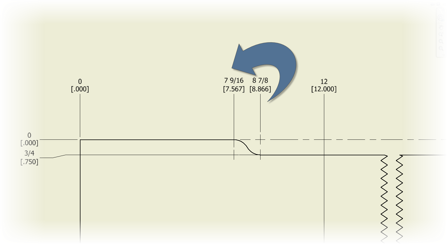
How do I rotate my ordinate dimension text 90 degrees?
The next I need to rotate
It's a question that comes up every so often, goes away, then comes back.
Looking back in my archives, I've realized I've never created a blog post for this one, so here it is. How to rotate ordinate dimension text 90 degrees!
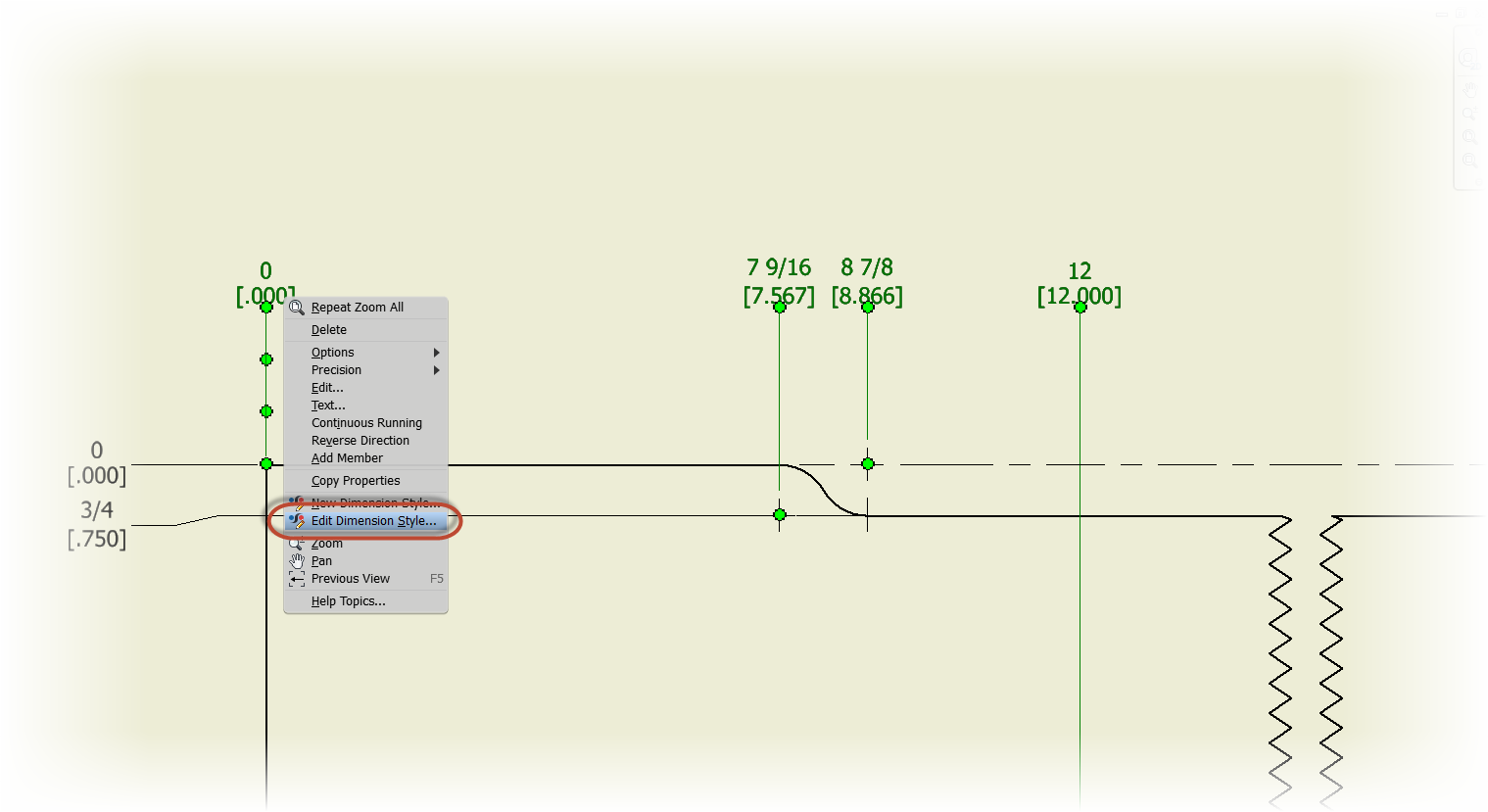
First, choose the dimension style I want to edit, right click, and select "Edit Dimension Style". I can also go to the Styles Manager on the Manage tab, but the right click method is a little quicker I think.
Editing the dimension style
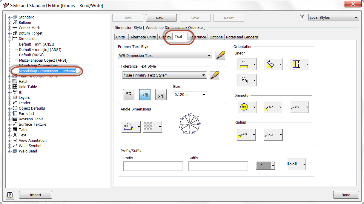
The Dimension Style Editor appears, selected the dimension style. Click the "Text" tab.
The text tab, where to look
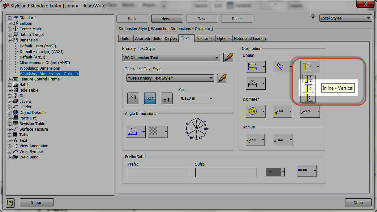
This section contains the settings for text orientation. Select the "Vertical Orientation Tab", and rotate the text to be vertical instead of the default, which is horizontal. Save and close the Dimension Style Editor.
Changing the setting
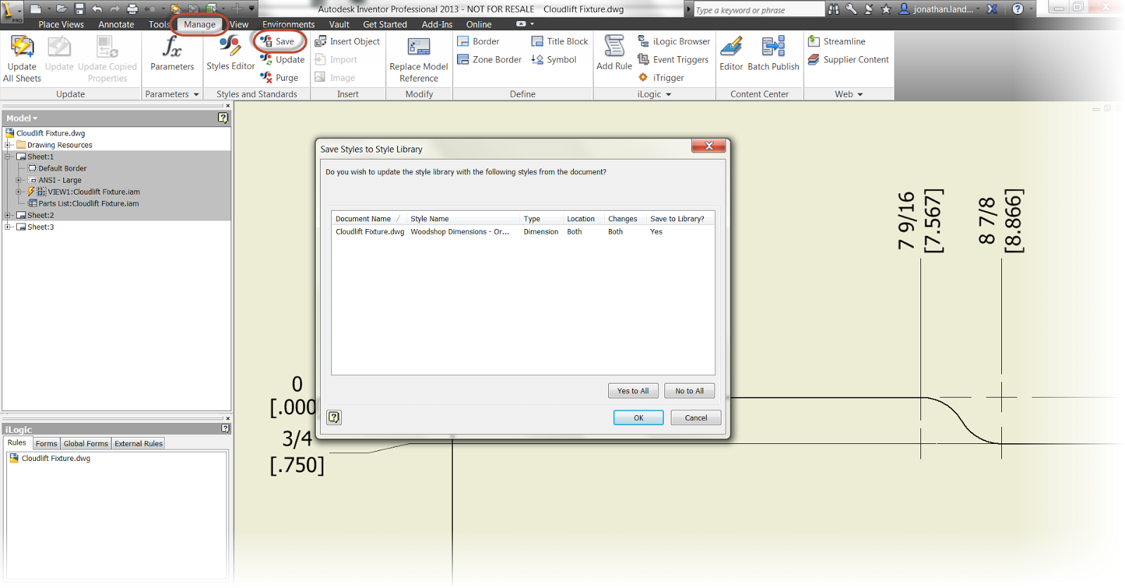
And it's done! One last step would be to save it to the styles library, and make sure it's available to all the drawings, if desired.
Saving to the Styles Library.
But that is it. As I've said too many times before, 'Not hard, when you
know where to look". But indeed, it's just a matter of looking in the
right place.
And naturally, there has to be a video that goes with it, so here it is!


