Find us on Google+ Inventor Tales: Inventor Drawings
Showing posts with label Inventor Drawings. Show all posts

Tuesday, January 15, 2013

Embedding vs. Lilnking images in Autodesk Inventor - The Poll's have Closed

“I'm not going to have opinions. I'm not going to cause problems. I'm going to go with the flow.”
Milton Bradley

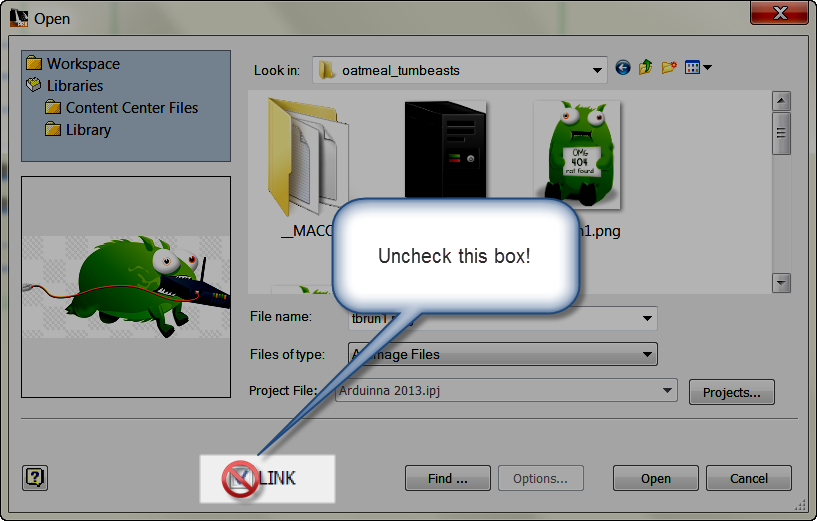
A couple of weeks ago, I posted a blog on embedding images to title blocks in Autodesk Inventor, and stated that embedding is my personal preference.

That blog received comments from a few users who strongly favor linking images in, for a variety of reasons that are completely reasonable.   Those comments can be seen on the original post linked above.

I also got responses on my Twitter account from users who had equally strong opinions favoring embedding.

Inspired by this I tried my hand at creating a survey on embedding images into Autodesk Inventor's drawing resources, or linking them.  Just to see what the "interverse" would say.

 I left the survey open for about a week, and the results are in!

The responses to the survey weren't huge.  26 people in total responded to my poll.  Of those 26 responses, 23 favored embedding images, and 3 favored linking.
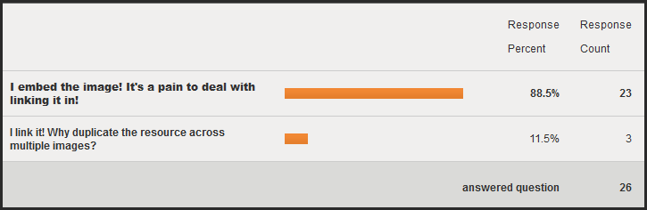


The results are in!


So from this small survey, what conclusions do I draw?  That is, other than 23 out of 26 people prefer embedding? 

While my inbox wasn't flooded with responses, I would say the results are consistent with my experience "in the field". 

I could also say that I've been validated, seeing how embedding is what I prefer to do on my personal files. 

Yay me. 

But in this respect, I'm no different that the average CAD jockey.  I'm just a user that's made choices based on my own, personal needs.

So validating my personal opinions isn't what I was after.  And for those of you who might be wondering, I did not cast a vote on this poll!

I've learned that there is a strong minority that does prefer linking.  Those who prefer that method have thought this out, and are also drawing conclusions based on their design needs.

So, to quote corporate America, "What's our takeaway?' 

Most users seem to favor embedding, but there is also a minority that strongly prefer linking images in. 

My ultimate, personal, conclusion?  Keep calm and carry on.


I'm perfectly happy embedding my images, and I'm sure most of the 23 who voted for embedding agree.

For those 3 who represent the "linkers"?  Link away!  If linking makes your jobs easier, then by all means, LINK!

It was never my intention to change any one's mind.  Only to find out what choices users are making, and share those results back out to the user community.

So thanks for those who took a few minutes out of their day to share there responses.  I appreciate the participation!  Maybe I'll try another poll on this later on.  Just to see how things have changed!

Thanks again everyone!

Sunday, January 13, 2013

Copying a Drawing Sheet from One Drawing to Another in Autodesk Inventor

“Someday I hope to write a book where the royalties will pay for the copies I give away.”
Clarence Darrow

Last week, I put up a post describing the steps I use to copy a view from one sheet to another in Autodesk Inventor  But what if I want to copy a sheet from one drawing file, to another?

There are some simple steps for that process too.

For my example, I want to copy a drawing sheet of an assembly from one drawing to another.  In order to accomplish this, these are the steps I like to use.

1) Have both the drawing file including the source sheet and the destination drawing file open at the same time.  I like to cascade them so they're stacked on top of each other.

This is the setup I like


2) Right click on the sheet to be copied in the browser and choose the "Copy" command.

Right click on and choose "Copy"


3) Activate the destination drawing by left clicking on in the drawing.

Click to activate the next sheet

4) Right click on the destination drawing's name  in the browser, and choose "Paste".  Note that in the image below, the name (Drawing1.dwg) is highlighted blue.


Pasting in the new sheet

5) The sheet will appear in the new sheet.

The sheet is duplicated in the new drawing

It's as simple as that. 

For an added tip!, The drawing sheet can now be reordered by dragging and dropping inside the browser.  That makes sure it's exactly where you want it.

I have also, in my travels, found a couple of additional tricks to be aware of going forward.

1) Make sure to have the source and destination drawing files open at the same time.  Opening the source file, choosing "Copy", then closing the source file won't work.  The Paste option won't appear.

I don't know why this is.   But it's something to be aware of.

2) If you want to copy the entire drawing sheet from one view to another in the same drawing, open a template and copy to the new drawing first.  Then, copy it from the  new drawing back into  the original.

Trying to duplicate the sheet in the same drawing without using an intermediary file doesn't work.  The paste option won't show.

Again, I don't know why this is.  I just know that it is.

These are a few more tricks that I use when I need them.  And while I don't need them often, they've helped me quite a bit in the times that I have needed them. 

If you'd like to see a video where I show the steps I've used, just check out the video below!


Tuesday, January 08, 2013

A User Poll! Do you embed, or Link Images in Your Autodesk Inventor Drawings?

“It's honesty. You may not agree with him, but you know where he stands.”
Rosemary Thompson

Back on January 2nd, I wrote a blog post regarding embedding versus linking images into Autodesk Inventor drawing resources, such as inserting a logo into a title block. 

Interestingly enough, I've had some fascinating comments from blog, my Twitter feed, even a personal conversation or two that seem to indicate that there are some strong opinions on both side of the fence.

It's plain to see in my post that I prefer embedding the images.  While I see some benefits to linking, they've never been enough to outweigh the headaches that I've encountered in dealing with them. 

But those who disagree with me aren't just shaking torches and pitchforks.  They've brought up solid reasons for their stance as well.

So I've decided to take this as an opportunity to try my first poll, and ask the world at large, what do you prefer?  I'm sure there will be some spirited opinions, and I interested to see what they'll be.

You'll find the survey below.  Bear with me for any failings, this is my first attempt and I'm sure there will be a mistake or two! I'll keep the poll open for a week, until January 15th, and we'll see what the results are!

Feel free to add your thoughts to the comments below, all I ask is that it be kept civil.  No flame wars, etc. 

Thank you all for your input!

Create your free online surveys with SurveyMonkey, the world's leading questionnaire tool.

Sunday, January 06, 2013

Copying Drawing Views from One Sheet to Another

“Drawing is putting a line (a)round an idea.”
Henri Matisse

I know I've had to do this a few times back in my design days, and I know that others out in the "DrafterVerse" have faced this also.

How to copy drawing views from one sheet to another in Autodesk Inventor drawings?

I remember having cases where I needed to create a drawing view on a separate sheet that was almost the same as one on a previous sheet.  Perhaps I needed to change some notes, or possibly remove or add annotations.

In each one of these cases, the last thing I wanted to do was recreate the view and annotations all over again.

But there are ways that views and sheets can be copied with very little difficulty.

So how can a view be copied from one drawing sheet to another?

  • I'll start out with a drawing that has the sheet I want to copy.  This happens to be a base plate for a wood routng jig. 

The sheet I need to copy


  • Next, I create a new sheet in this drawing set.  This is the destination for the copy.


The new sheet ready for a copy

  • Now that I have a destination sheet, I can switch to my source drawing.  I select the views I want to copy (use the "CTRL" key to select multiple views).  Right click and choose "Copy".

Copying the views from the source sheet. 


  • With the views copied to the clipboard, I can paste them to the destination sheet by selecting the sheet's icon in the browser, right clicking, and choosing "Paste".   

Pasting the view

  • The view will appear on the new sheet.  Now the annotations can be changed as needed!

The completed view.  Dimensions removed, and a detail added.
And here's a video to go along with the steps above!


In other Inventor Tales news!

I've finally decided to grab www.inventortales.com as a domain for this blog.   Don't worry, the old links with www.inventor-tales.blogspot.com still work, but now there's a shorter link that can be used to get to Inventor Tales! 

Wednesday, January 02, 2013

Inserting vs Embedding Images in Title Blocks in Autodesk Inventor

“Break one link and the whole chain falls apart”
Proverb

Now that the we've all survived the Mayan Apocalypse and are cruising through the first few days of 2013, here's a simple post to kick off the new year.

One thing I've had to do several times is import a logo into a the title block on a drawing.  The process is straight forward, and dare I say easy.  As a matter fact (insert squinty eyes), it's too easy.

The danger is that by default, the image is actually linked into the file.  Not embedded. 

Personally, I hate linking the image to the title block.  In my experience, it seems like the image gets lost, or there are multiple copies of the linked image floating around, inevitably causing what could be a minor data management nuisance to a full fledged headache!

Just imagine using Vault with Unique File Names Enforced, and being unable to check in a file because there's already a file named "logo.bmp"!

Needless to say, I always embed my logos.  I find it works a lot easier for me in the long run.


So in this post, I'll go over the steps to insert a logo into the title block, and the step that makes sure the logo is embedded instead of linked.

First, edit the definition of the title block by right clicking on it in the browser, and choosing "Edit Definition".

Editing the definition of the title block.

Now the Sketch Ribbon becomes active.  Click on the "Image" icon to insert an image.

Inserting the image

The next step is to draw a rectangle where the image will reside.  A dialog box will appear asking you to select the image to insert.

Inserting the image.  Tumblr Beasts courtesy of TheOatmeal

This is the point where it pays to stop and look at the dialog box.  Notice the "Link" checkbox?  It's checked by default!

The link box.  I uncheck this.

 If left checked, the image will link from it's current location.  That means the image must always be accessible by the file, and cannot be moved, deleted, etc.  This is why I've always preferred to embed the image. 

By unchecking the "Link" box, the image will now embed in the document, instead of linking.  Now it doesn't matter what happens to the original image.  The title block carries the image with it in the document from this point forward.

Image embedded


There are the steps to insert an image, with that vital stumbling block of the link checkbox.  Watch out for that step.  It's a doozy! 

And out of my curiosity, and that of everyone out in the 'Verse, is anyone out there prefer to link the image instead of embed it?   Throw out a comment below.  I'd love to see how you're making it work! 

If you agree with embedding the image.  Throw a comment too!  I'm a curious soul, and I always like to see who is doing what!

Thursday, December 27, 2012

Splitting Tables in Autodesk Inventor

“Let the gentle bush dig its root deep and spread upward to split the boulder.”
Carl Sandburg


As I'm waiting for 2013 to arrive, I came across a little tip in Autodesk Inventor that it could be said falls into the "I never noticed that" section. 

Splitting a hole table.

Once upon a time, when I was designing stamping dies, there were many a time that the hole table describing all the holes in a die plate would run off the page. 

Back at that time, I was using AutoCAD, so breaking was a matter of inserting and manually populating blocks.  

But what happens if the same thing needs to be done with Inventor?  Below is an example of a hole table I want to split.  I know the table isn't that long, and probably doesn't need to be split in this case, but bear with me, it's just an example!  Besides, I didn't feel like modeling a part that did run off the page!


A table in need of splitting

Let's say I want to split the table at the row 'C1'.  All I have to do is right click inside one of the fields, and choose "Table>Split Table".


Splitting the table.  Make sure to click inside one of the fields
After choosing the "Split Table" option, the table will split at that cell.  Click and drag on the tables to reposition them.  The hole table can then be split again, and again, as needed!

Repositioning the newly split table.

That's all there is to it!  But there's a couple of other tips worth knowing. 

1) If the table needs to be "recombined", right click on the table, and choose Table>Un-Split Table

Combining a "un-splitting" a split table.

 
2) This is very important!  Don't click on the border of the cell! The "Split Table" option will gray out if the border of the cell is clicked on!


This is what happens when clicking on the border of a cell!
So that is today's short little tip.  A few tricks that I hope are helpful. 

Have a few thoughts you want to share?  Feel free to drop a comment or two!

Sunday, December 09, 2012

A Quick Tip on Positioning Section Lines in Autodesk Inventor

“I went to a bookstore and asked the saleswoman, "Where's the self-help section?" She said if she told me, it would defeat the purpose”
George Carlin

Creating section views with Autodesk Inventor.  It's not a difficult thing.  But there is a trick I sometimes use that I think is worth sharing on how to position the section line. 

The most common way, is to choose one of the projected construction elements.  This will grab things like the center or quadrant of a circle, a midpoint of a line, or a vertex where two lines meet.  This probably covers nearly all cases of what most users need to do.

The construction element

But what if there's a case where a section line needs to be placed a certain distance from the edge, and no convenient point exists?

First, place a section line on the view, but don't let it constrain to anything.  I like to place the section line completely off the view geometry to make good and sure I don't pick a point by mistake.


Placing the section line "off the geometry".


Now with the view placed (it looks like a projected view right now), right click on the section line, and choose "Edit".

'
The section view completed off the geometry

Now to edit the placed view

Now the sketch the section line lives on becomes active, and it can be positioned using constraints and dimensions, just like any sketch.  One important thing to note.  Make sure to use the "Project Geometry" tool to project geometry off the view.  Otherwise it can't be picked.

Use project, constrain, and dimension to position the section line.


Once the geometry is projected, it can be constrained and dimensioned like any sketch!

The completed section view

Do you have  a place this might be helpful!  Drop a comment!

And naturally, here is the accompanying video!

Saturday, November 24, 2012

All for Fun! Now, the 4 Sided Gaming Die

God may not play dice with the universe, but something strange is going on with the prime numbers.
Paul Erdos

With this description of how I built the four sided gaming die, my series is nearly coming to a close. 

The completed four sided die.  The yellow "spines" are the work axes used for the circular number to complete the numbers

 This is a recreation of a die I created for a friend who was making a website for Dice House Games in Fullerton.  Ironically, they're right next door to the KETIV office!

I had to recreate the die because I lost the model in between laptops, but I think this is a better design that the original.  So here it is for everyone!

This particular die was pretty simple.  The construction was nearly the same as creating half of the eight sided die.  Although there were some variations with the numbers and basic construction.

The first step, was to create a triangle on an origin work plane.  This becomes one base of the die.

Starting the 4 sided die

\Next came a challenge.  I needed to create a point on the midpoint bisector of the triangle.  For this, I had to reach back into the high school geometry I swore I'd never use!  In truth, I only needed two lines, but the third helped me make sure that everything was right!

Bisecting the triangle

With this construction complete, I could now place a point on the intersection of the lines, and a line through that point, and perpendicular to the plane of the triangle.

I next made sure to make the hypotenuse of the imaginary triangle made by the line the same length as the side of the first triangle I sketched (a screen capture probably makes more sense here). 

Creating the line perpendicular to the first sketch.
Now I lofted from the triangle, to the point I created.  That's it, now I have a four sided die!

Creating the loft that creates the die.
 And next I break the sharp edges with a fillet.

Breaking the sharp edges
 And now the numbers!  In this case, the numbers were actually a little easier.  Instead of creating each number one at a time, the shape and design of the four sided die allowed me to use a work axis and utilize the "circular pattern" tool to finish out each number.  This way, I only had to position each number once.  The circular pattern took care of the rest!


Using a circular pattern makes it easy to create the numbers!


And viola!  The four sided die!


And I'm done!

Of course it wouldn't be finished without a rendering in Autodesk Showcase.


An now a  little rendering!

If you'd like, you can download the file from the pages below!

Click here to download from GrabCAD (login required)

Click here to download from Autodesk 360  (No login required)

Have any questions on a particular step?  Throw out a comment! 

Also, I'll be at Autodesk University 2012 this year in Las Vegas, so you may see my bald head roaming around!   

I'm also planning on blogging from there, so look for some (hopefully) interesting stuff!


Sunday, November 18, 2012

Creating a Breakout View in Autodesk Inventor

“A dream is your creative vision for your life in the future. You must break out of your current comfort zone and become comfortable with the unfamiliar and the unknown.”
Denis Waitley

When I training Autodesk Inventor, I always take a little bit of extra time on the break out view in drawings.  It's a great way of showing details for internal parts inside an assembly, and not difficult to create in Inventor.

A break out view shown created

 But when creating a break out view, it's got one place that usually snags everyone as the first few times they use it.  I know it got me when I first started it.

 That step is, associating the sketch to the view.  If the sketch isn't associated to the view, the break out view won't work, and the breakout command will error out.

This is the error seen when the sketch isn't associated
So how is the sketch associated?  What is it that's so special?

I'll talk about all the steps, and specify that special step to create the sketch association.

1. Click on the view that the breakout view will be placed on. The border will highlight, indicating it's selection.  This is the critical step that will create the associated sketch!

Make sure to select the view before creating the sketch!


2. Now, click the "Create Sketch" icon.  The sketch is created, and it's axes will center on the view.  It's this centering of the axes that tells us the sketch has associated to the view.

Creating the sketch

The centered axes tell us it's working
3.  Now sketch a closed figure around the area to break out. It can be any shape, it just has to be closed.  Here I use a spline. Finish the sketch when done.

Sketch the break out view boundary


4. Now click on the "Break Out" icon.   Select the sketch with the view.

The break out icon

5. Define the options for the break out.  One helpful tip is to point out that projected views can be used to help with the definition, not just the view that will host the breakout.  In the image below, I've used a projected view to define the break out depth.

Setting the options for break out


6. Choose okay and the breakout view is created.

The break out view created

 I could say "That's All Folks", but instead, here's a couple of other tips that I find helpful.

There will be times that not every component in the break out view is supposed to be sectioned, as step 6 shows above.  Here's how to change that.

The first is to locate the part in the feature browser, right click on it, locate "Section Participation", and changed it's setting to "None".

Setting the section options from the browser

The other is to hold down the "Shift" key with nothing selected, and right click.  Choose "Part Priority" from the menu.

Setting part priority


Now select the part on screen, right click, and the same options for "Section Participation" are available.

Setting the section participation from the right click menu


Which ever means you prefer, the sectioning for selected components can be turned off, if desired.

A completed section, with specific parts unsectioned

On a last tip, I've shown what happens when the selections are correct, but how can you tell when the view isn't associated, so a mistake can be quickly corrected before the error on view creation appears? 

There are two quick ways to tell.

1. If the sketch is created, but the axes aren't centered on the view, the sketch isn't associated.

2. If the "Project Geometry" icon is grayed out, then the sketch isn't associated.  This is because Inventor doesn't see any geometry to project.  If the sketch is associated it will.

Two ways to tell if the sketch isn't associated
 In conclusion, I hope this helps a few of you out in the "Verse" with break out view.  It's a great tool, and can be a great way to add informative detail on a drawing.

For a little extra info, here is the video!


<