“If you're going to build an airplane, first you have to know how to bend sheet metal, and before that you have to know how to render iron from the ground.”
Eric Henderson
The last couple of weeks have been a non-stop rush, so blogging has definitely been a tough thing to get to lately!
But the lessons never stop! Learning is a dance that is in constant motion!
While I was sitting in an Autodesk Inventor update course earlier this week, the instructor shared some fantastic sheet metal links and encouraged us to pass them on, so that's exactly what I intend to do!
And why am I sharing these resources? I mean aside from the fact that the instructor told us to?
The one thing about using sheet metal in Autodesk Inventor, is it's a tool. And like so many tools, it takes the knowledge of the user to really make it reach it's full potential.
One thing has not changed. Experience counts. Pure and simple.
The resources I'm sharing are intended to help obtain that experience. They let us, as users, assimilate the knowledge we need to make us more knowledgeable, which in turn allows us to use the tools to amplify that knowledge.
So at last, here are the resources past onto us by the instructor.
Bend Calculator from the SheetMetalGuy.com, Do you need help generating K-Factors and bend tables, here's a place to start. Here's a direct link here!
The next, is from www.bendallowance.com. Follow the direct link here to a list of formulas used to calculate sheet metal setbacks!
Third on the list is from Sheetmetal.me and is a resource for designers, operators, and "anyone else interested in sheet metal manufacturing". It has great resources for calculating bend allowance on this page.
The last of the four big websites, have a look at this link at Custompart.net to calculate things such as bend allowance, setback, and stamping forces.
Finally, another place to try is the Google Apps store. There are tons of Sheet Metal Apps that are available.
I haven't tried any, but they com recommended, and if you us sheet metal, and have an Android, it's worth a look.
For you Apple users, I have been told there are apps, but not as many. But not as many. I can't speak to this myself, but if you have an Apple App you like, feel free to throw a comment down below!
Showing posts with label Inventor Sheet Metal. Show all posts
Showing posts with label Inventor Sheet Metal. Show all posts
Friday, May 23, 2014
Monday, April 07, 2014
Choosing a Sheet Metal Base Face before Creating a Flat Pattern in Autodesk Inventor
Simon: I'm trying to put this as delicately as I can... How do I know you won't kill me in my sleep?
Mal: You don't know me, son, so let me explain this to you once: If I ever kill you, you'll be awake, you'll be facing me, and you'll be armed.
Simon: Are you always this sentimental?
Mal: I had a good day.
Exchange between Simon Tam and Mal Reynolds in the television series "Firefly"
The trick I share this week is one I've actually known about for a while. As a matter of fact, it's become part of my "background knowledge". Something that has become second nature.
I've known it so long, I can't remember when I didn't know it. f
But I'm sure there are those that may not know it, so I choose to share it today.
When unfolding a sheet metal part in Autodesk Inventor, inventor chooses which face is going to be shown to the user via it's own means.
It might be considered common knowledge that the face can be changed in the flat pattern screen by right clicking on the Flat Pattern icon in the browser, and choosing Edit Flat Pattern Definition.
This tool invokes the Flat Pattern Definition dialog box. This has a button where the flat pattern can be flipped.
But there's another way that it can be done before the flat pattern is created.
Just pick the face you want to see before hitting the flat pattern icon, and that will become the "Base Face"
And if you really want to make sure, change the color of one of the faces to a different color by selecting it and right clicking. Give it a try! It works!
And for those who prefer a video format, here you go!
Labels:
Inventor Sheet Metal
Thursday, May 24, 2012
Where's my "Show All Constraints" Tool?!? - Autodesk Inventor 2013
“If we are facing in the right direction, all we have to do is keep on walking.”
Buddhist Proverb
Show All Constraints. It's been in Autodesk Inventor since I started way back in the days of Release 4. It was available from the right click menu, or by hitting the F8 key.
Just today I fired up Inventor 2013, and started up Inventor 2013, created a sketch, and right clicked to show all my constraints.
Guess what? It wasn't there! The hotkey (F8) still works, but it wasn't on the right click menu any more.
I puzzled for a second, then I face-palmed.
I remembered reading in the What's New for Autodesk Inventor 2013 that it was moved to the new Status Bar at the bottom of the screen!
Along with the Show Constraints tool: some other familiar tools have been moved there (listed in order, from left to right):
But I like the old way better!
Now, I know that there are those out there who are asking; "Why can't we make it like it was in 2012 and earlier?"
If you are on that team, you're in luck!
Go to the "Tools' ribbon, and choose the "Customize" icon.
On the dialog that appears, choose the "Marking Menu" tab. Then in the lower left hand side, pull the fly-out open and set the Overflow Menu to "Full Menu".
Click "OK" and the settings will be back to the older style settings!
So there it is, a few of the Inventor 2013 changes, and some ways to go back to your last release settings.
I hope the tip helped!
Buddhist Proverb
Show All Constraints. It's been in Autodesk Inventor since I started way back in the days of Release 4. It was available from the right click menu, or by hitting the F8 key.
 |
| The right click menu from Inventor 2012. The "Show All Constraints" option is there like it's always been! |
Just today I fired up Inventor 2013, and started up Inventor 2013, created a sketch, and right clicked to show all my constraints.
Guess what? It wasn't there! The hotkey (F8) still works, but it wasn't on the right click menu any more.
I puzzled for a second, then I face-palmed.
I remembered reading in the What's New for Autodesk Inventor 2013 that it was moved to the new Status Bar at the bottom of the screen!
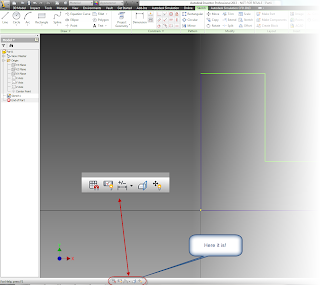 |
| I found it! |
Along with the Show Constraints tool: some other familiar tools have been moved there (listed in order, from left to right):
- Snap to Grid
- Show/Hide All Constraints
- Dimension Display
- Slice Graphics
- Show/Hide All Degrees of Freedom
But I like the old way better!
Now, I know that there are those out there who are asking; "Why can't we make it like it was in 2012 and earlier?"
If you are on that team, you're in luck!
Go to the "Tools' ribbon, and choose the "Customize" icon.
 |
| Choose Customize |
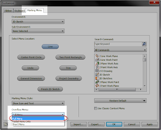 |
| Tada! |
 |
| Back to "old school" |
I hope the tip helped!
Sunday, May 20, 2012
Migrating Colors and Materials into Autodesk Inventor 2013
“A hard fall means a high bounce... if you're made of the right material.”
A new change in Autodesk Inventor 2013 is how materials and colors are handled. Instead of being a part of the Styles and Standards libraries, like in previous versions of Inventor. Now, they're stored in Appearance Libriares (for colors), and Material Libraries (for materials).
The location of the new libraries can be seen by looking at the project file.
But what if there are old libraries that have been created over time? We wouldn't want to throw them out and start over right. So there has to be a way to migrate them, right?
Well, of course there is! (or else I wouldn't have anything to blog about).
But how are the libraries migrated?
It's fairly simple, once you know where to look, as I'm so fond of saying,
There are two places to access the Appearance and Materials Libraries.
The first is from the quick access toolbars.
The second, off the Tools Ribbon on the Materials and Appearance Panel.
Choosing either icon will bring up the browser for that particular library.
Migrating to both the Material and Appearance Libraries is a matter of clicking on the "gear" icon in the lower left hand selecting "Migrate Inventor Styles".
The source (the library to be migrated) is selected, followed by the destination library.
However, there are two destinations to send your migrated folder, one is to create a new library, the other, select an existing library.
So what to do?
There's two theories. One is to migrate your old libraries to a newly created one, and remove the old Inventor libraries. This makes sure you have "one truth" for those materials.
The other, is to merge them into the existing library. The important, custom materials will be there.
Which did I choose? Personally I used "Create New Library. For me, it was a little easier to have that "one version" of the truth. I can remove one library later if I don't want it.
Hit okay, and the migration begins.
Soon, the migrated Material Library is complete.
The best part now, migrating the Color Library to the Appearance Library. Why is it so good? It's basically the same steps! If you've done the Material Library, you can do the Appearance Library.
Naturally, it wouldn't be a blog post without a video. So here we go!
Do you have input on how you might have migrated your own libraries! Throw a comment below!
P.S. If you're interested in how to migrate Dimension Styles, Sheet Metal Styles, etc. Check out last week's blog here!
A new change in Autodesk Inventor 2013 is how materials and colors are handled. Instead of being a part of the Styles and Standards libraries, like in previous versions of Inventor. Now, they're stored in Appearance Libriares (for colors), and Material Libraries (for materials).
The location of the new libraries can be seen by looking at the project file.
 |
| The libraries as shown in the Project File |
Well, of course there is! (or else I wouldn't have anything to blog about).
But how are the libraries migrated?
It's fairly simple, once you know where to look, as I'm so fond of saying,
There are two places to access the Appearance and Materials Libraries.
The first is from the quick access toolbars.
The second, off the Tools Ribbon on the Materials and Appearance Panel.
 |
| On the Tools Ribbon |
Migrating to both the Material and Appearance Libraries is a matter of clicking on the "gear" icon in the lower left hand selecting "Migrate Inventor Styles".
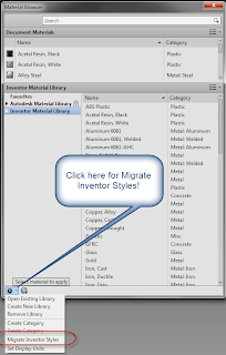 |
| The dialog for Materials. The Appearance dialog is nearly identical. |
The source (the library to be migrated) is selected, followed by the destination library.
However, there are two destinations to send your migrated folder, one is to create a new library, the other, select an existing library.
So what to do?
There's two theories. One is to migrate your old libraries to a newly created one, and remove the old Inventor libraries. This makes sure you have "one truth" for those materials.
The other, is to merge them into the existing library. The important, custom materials will be there.
Which did I choose? Personally I used "Create New Library. For me, it was a little easier to have that "one version" of the truth. I can remove one library later if I don't want it.
Hit okay, and the migration begins.
Soon, the migrated Material Library is complete.
The best part now, migrating the Color Library to the Appearance Library. Why is it so good? It's basically the same steps! If you've done the Material Library, you can do the Appearance Library.
Naturally, it wouldn't be a blog post without a video. So here we go!
Do you have input on how you might have migrated your own libraries! Throw a comment below!
P.S. If you're interested in how to migrate Dimension Styles, Sheet Metal Styles, etc. Check out last week's blog here!
Sunday, May 13, 2012
There's Been a Change or Two - Migrating Styles Libraries from Inventor 2012 to Inventor 2013
“Good as it is to inherit a library, it is better to collect one”
Augustine Burrell
When I first started working with Autodesk Inventor 2013, I thought that migrating the Styles and Standards (colors, sheet metal styles, dimension styles, etc), would be exactly the same as in 2012.
I even tried it, and everything worked fine.
But earlier this week a KETIV colleague, Javier Chavez, asked me a question.
"Have you noticed that the Design Data folder was restructured in Inventor 2013?
I hadn't noticed the change. But as we looked at Windows folder structure, discussed migration procedures, puzzled, and discussed some more, we found that the folder structure had indeed changed.
"That's going to make migration important." I understated.
So I deleted my Inventor 2013 Design Data, and tried it again. Sure enough, the process was different.
In brief, the biggest difference is Inventor 2012 (and earlier), migrated the data in place. So you copied your old data to a new location, and migrated it there.
Inventor 2013 on the other hand takes your data and copies it to the new location, migrating it during the process.
This was the difference I'd missed the first time.
So before I show you the video, here's one thing to always remember!
Have a backup of your Design Data folder!
I cannot stress this enough! If you make a mistake, you can always delete the migrated files, and try again with the backup you created.
As a matter of fact, I did this several times testing out the migration to make sure what I thought was going to happen, was really what was going to happen.
As I was once told. "If you think you don't need a backup. Stop and ask yourself the following question. When was the last time you regretted having a backup?"
In other words, make the stinking backup. It takes a few minutes, and can save you hours of having to live in the "Purgatory of Data Recreation".
Augustine Burrell
When I first started working with Autodesk Inventor 2013, I thought that migrating the Styles and Standards (colors, sheet metal styles, dimension styles, etc), would be exactly the same as in 2012.
I even tried it, and everything worked fine.
But earlier this week a KETIV colleague, Javier Chavez, asked me a question.
"Have you noticed that the Design Data folder was restructured in Inventor 2013?
I hadn't noticed the change. But as we looked at Windows folder structure, discussed migration procedures, puzzled, and discussed some more, we found that the folder structure had indeed changed.
 |
| Notice the difference between folder structure in Inventor 2013 (left) & Inventor 2012 (right). |
"That's going to make migration important." I understated.
So I deleted my Inventor 2013 Design Data, and tried it again. Sure enough, the process was different.
In brief, the biggest difference is Inventor 2012 (and earlier), migrated the data in place. So you copied your old data to a new location, and migrated it there.
Inventor 2013 on the other hand takes your data and copies it to the new location, migrating it during the process.
 |
| Source folder, destination folder, and a waiting migration button! |
This was the difference I'd missed the first time.
So before I show you the video, here's one thing to always remember!
Have a backup of your Design Data folder!
I cannot stress this enough! If you make a mistake, you can always delete the migrated files, and try again with the backup you created.
As a matter of fact, I did this several times testing out the migration to make sure what I thought was going to happen, was really what was going to happen.
As I was once told. "If you think you don't need a backup. Stop and ask yourself the following question. When was the last time you regretted having a backup?"
In other words, make the stinking backup. It takes a few minutes, and can save you hours of having to live in the "Purgatory of Data Recreation".
Thursday, January 19, 2012
KETIV's 2011 Autodesk Manufacturing Academy Recordings are Out!
“Nothing has really happened until it has been recorded”
Virginia Woolf
At long last! After much hard work, the bow tie on the 2011 edition of KETIV's Autodesk Manufacturing Academy!
The videos! They're all up and ready for download!
So if you've attended the classes presented by the the KETIV technical team, or even if you didn't attend, and want the benefits of the course materials. Take a swing by the session archive and download all the materials!
Click HERE for the link to download the materials!
Fire away and start eating up some bandwith! ;-) You can even download the 2010 and 2009 materials too!
I hope those who attended took some useful things away! Go
I hope to see you all, (and a few more) at the next 2012 KETIV AMA!
And as a trailer for the movie, here's a sample of the classes on Autodesk Showcase, so you can get an idea of what's available!
Special thanks to Tolar Manufacturing for providing us with some great real world samples to use in the session!
Autodesk Showcase Part 1 - Importing Models
Autodesk Showcase Part 2 - Changing Environments
Autodesk Showcase Part 3 - Assigning Materials
Autodesk Showcase Part 4 - Changing Materials
Autodesk Showcase Part 5 - Adding Lights
Sunday, October 16, 2011
Documenting Sheet Metal Punches on Drawings
“Chicago is a city of contradictions, of private visions haphazardly overlaid and linked together.”
Pat Colander
Now I've returned from Autodesk training in Chicago. The training was informative, and well executed. Now to absorb all the information! I'll be sharing some of that knowledge as I apply it to my real world.
For this blog, I wanted to continue the lesson from my last blog post, where we created a sheet metal iFeatiure
In that last blog, Creating Sheet Metal Embosses, we saw how we could create a sheet metal punch. Now, we'll see how we can reuse that punch, and place it on a drawing. Once you place it on the drawing, you're able to annotate it, and take advantage of the information you placed on your punch.
Take a look at the video, and see! We've also added some fancy new "Intros & Outros". Let us know what you think!
Labels:
Inventor Drawings,
Inventor Sheet Metal
Monday, September 05, 2011
Wash, Rinse, Repeat (my work features)
“It is not worthwhile to try to keep history from repeating itself, for man's character will always make the preventing of the repetitions impossible”
Mark Twain
While enjoying the day off for Labor Day here in the United States, I got to thinking about some of the settings I change right away on a new installation in Autodesk Inventor.
One of those settings is the "Repeat Command" option in Work Features.
The default behavior for Inventor when your placing a work plane, work axis, or work point is to place the work feature, then exit the command.
While many users like that functionality, I like to stay in the command until I exit with the escape key, or by right clicking and hitting "Done".
Fortunately, Inventor allows for this. While in the Work Feature command, right click and check "Repeat Command". From that point forward, the command won't exit until you tell it to.
It's a nice little feature, and one not everyone knows about!
Check out the quick video!
And for all you social media fanatics out there, check out KETIV's Autodesk Manufacturing Academy website on Facebook. Become a fan!
Mark Twain
While enjoying the day off for Labor Day here in the United States, I got to thinking about some of the settings I change right away on a new installation in Autodesk Inventor.
One of those settings is the "Repeat Command" option in Work Features.
The default behavior for Inventor when your placing a work plane, work axis, or work point is to place the work feature, then exit the command.
While many users like that functionality, I like to stay in the command until I exit with the escape key, or by right clicking and hitting "Done".
Fortunately, Inventor allows for this. While in the Work Feature command, right click and check "Repeat Command". From that point forward, the command won't exit until you tell it to.
 |
| Repeating a Work Feature Command |
It's a nice little feature, and one not everyone knows about!
Check out the quick video!
And for all you social media fanatics out there, check out KETIV's Autodesk Manufacturing Academy website on Facebook. Become a fan!
Sunday, October 03, 2010
Creating a Cooling Grill in Inventor Sheet Metal - By Using Plastics Tools
“The wise adapt themselves to circumstances, as water moulds itself to the pitcher”
Chinese Proverb
Inspiration comes from unique directions at times. I've been offsite working with a lot of electronic encolsures, which has been a fantastic experience for me. But that's a story for another day.
While speaking with one of our techs, Mike Carlson about the project, the subject of cooling grills came up.
Try using the grill from the Plastics tool set, he suggests.
I pause for a second. I think there was a visible light bulb over my head. My wheels spin for a second at at my first instinct, which is to blurt out, "That's a plastics tool, you can't use that in sheet metal!"
But my brain processes the information. It can't find a flaw in that plan. Instead my answer is "Bloody hell, that will work!"
I try it at my first opportunity. Sure enough. It works great.
So here it is! Thank Mike Carlson for the inspiration. I can't take the credit.
How to create a cooling grill in Inventor's sheet metal environment.... using plastics.
Chinese Proverb
Inspiration comes from unique directions at times. I've been offsite working with a lot of electronic encolsures, which has been a fantastic experience for me. But that's a story for another day.
While speaking with one of our techs, Mike Carlson about the project, the subject of cooling grills came up.
 |
| An example of a fairly typical cooling grill |
Try using the grill from the Plastics tool set, he suggests.
I pause for a second. I think there was a visible light bulb over my head. My wheels spin for a second at at my first instinct, which is to blurt out, "That's a plastics tool, you can't use that in sheet metal!"
But my brain processes the information. It can't find a flaw in that plan. Instead my answer is "Bloody hell, that will work!"
I try it at my first opportunity. Sure enough. It works great.
So here it is! Thank Mike Carlson for the inspiration. I can't take the credit.
How to create a cooling grill in Inventor's sheet metal environment.... using plastics.
Sunday, July 11, 2010
Taking a Sampling - Where Did My Inventor Sample Files Go?
“The proof of the pudding is in the eating. By a small sample we may judge of the whole piece.”
Miguel de Cervantes Saavedra
Last week I was fortunate enough to receive my new laptop. 64bit Windows 7, 8 GB of RAM, 500GB hard drive. It'll be a dream for at least the next 6 months, before the next dream box comes along.
Of course with that comes the installation of the software I'm using. To date, I have Inventor, Vault, and Showcase installed. Not to mention Snagit, Camtasia, and several other small programs I usse
After getting my system ready I found that I need to run a quick test on some files. No problem! I'll just grab a sample file! There's sheet metal parts, assemblies, drawings, a slew of flies I can use for a quick test when I don't have the time or desire to build a data set.
Well, when I went to get them, they weren't there! There were some iLogic files, a translator folder, and an html document named 'Where are my sample files'.

The 'Where'd they go file'
(click to enlarge)
(click to enlarge)
Not to fear, if you click on the html file, it opens up to a hyperlink that takes you to a page where you can download the files.
The link will take you to the download page but if you're reading this blog, you can just go ahead and follow the link here.
It definitely saves the disappointment of finding the location (which can vary if you're on Windows XP versus Windows Vista/7).
If you're a CAD Manager or IT in charge of getting the files, you can also download them and put them on a server instead of hunting for them when you're asked. Then you get kudos for being proactive!
Sunday, April 11, 2010
Taking on a Whole New Dimension - New for Inventor 2011
“There is a fifth dimension, beyond that which is known to man. It is a dimension as vast as space and as timeless as infinity. It is the middle ground between light and shadow, between science and superstition.”
Rod Sterling
For today, a simple tip. But if you can make use of this functionality, it's a big one!
Like a creature crawling from a swamp in a movie, I first heard this come up when I arrived on the scene to begin working on Inventor R4.
This was around the year 2000. We'd just averted the anarchy that was supposed to come from the Y2K bug, and we speculated on how wonderful life would be if we could have a full GIGABYTE of RAM on our machines.
The question seemed to come and go, depending on the user. For some, it wasn't a big wish, for others, they really hoped for it's inclusion in the next release.
What was that question?
Can I show fractional dimensions in a part file, instead of decimals?
At the time, the answer was no. And it remained that way until Inventor 2011. But now! Now you can show decimals in decimals, fractions, and architectural. All you have to do is right click in the Edit Dimension dialog box when you place the dimension.
You can also type the format directly in the Edit Dimension dialog box. For example
1in/8 will show the dimension as a fraction
1'6" will create the architectural dimension
There it is. I Maybe it doesn't have all the flash of the new Visual Styles, or the 'Gee whiz that's cool' of limit constraints (one of my favorites). But it's that solid little tool that can definitely be part of your daily arsenal!
Happy Inventing!
Monday, December 07, 2009
Autodesk Manufacturing Academy - Looking Back
“The Internet is becoming the town square for the global village of tomorrow.”
Bill Gates
I did something this weekend I rarely do. I took a vacation! Since I was on a snowboarding trip at Mammoth Mountain, there isn't much on the tech tip side.
But, there is something that is worth talking about.
With Autodesk Manufacturing Academy finished, the team here as been busy creating recordings of the lessons taught there for download by those who attended.
But..... For a limited time.... From the KETIV Technologies news desk..... The Sheet Metal videos are available for download for everyone!
You can read the press release HERE. The link is on the release. Be sure to check the archives! That's where the files are located!

A picture from the AMA site. Look in the Archives section
(click to enlarge)
(click to enlarge)
Take a look! We're really excited about it.
Oh, and as for that snowboarding trip.... The snow was icy, and the wind was howling so badly that we only were able to go up one day.
Here's a picture of the aborted day two. You can definitely see why we avoided that one!

It wasn't actually snowing. This is ALL the wind!
(click to enlarge)
(click to enlarge)
Monday, November 30, 2009
Defining Inventor Parameters. Making Inventor Remember, so You Don't Have to!
If you want to understand today, you have to search yesterday. ~Pearl Buck
Every once in a while, I run into one of those things that I've done so many times, that I take it for granted. But that's when I realize my assumption is really keeping a secret that shouldn't be kept.
This is one of those cases.
I've been working on and off (since I was on vacation, you could say more 'off') on my night stand for what is a future wood shop project. Actually, it's probably more like a distant future wood shop project!
At least give me a little credit. I've already built one night stand!
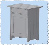
(click to enlarge)
If you've worked much in wood, the three dimensions that you can't avoid are 'Length', 'Width', and Thickness. In this project, at least one thing is certain. There's a lot of things that are related to one of these major dimensions.
Take, for example, the back panel shown here. I've colored it brown to make it stick out. It's compose of a panel, enclosed in a frame of rails (the horizontal pieces), and stiles (the vertical pieces).
And before you wordsmiths start pointing out that I've misspelled 'stile'. In word working, the 'stile' is the correct spelling for this part.
'Style' is what the finished night stand has, as in 'Wow, that night stand has some style!"
The panel slides into slots cut into the rails and stiles.
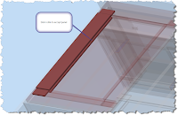
(click to enlarge)
The thickness of the rails and stiles are all .750 inches. I want the slot to be .250, or more precisely, 1/3 of the thickness of the rails and stiles that frame it.
Of course I could just build the slot, and type in '.250' to create the slot. After all, the math is pretty easy, right?
But what if the thickness changes? It's possible. Then I have to make sure that I remember to change the thickness of the slot to respect the '1/3rd rule' I've decided on.
Here's an easier way to remember that. Make Inventor do it!
When I built the part, I created parameters for Length, Width, and Thickness, among others. Here we're just going to focus on thickness, which is set to .750 inches
Editing the sketch that defines the slot, I can see that I've have it set to .250 inches, but there's no intelligence to it, I've just done math metally, and typed in the value.
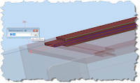
But, if I right click in the white field where the dimension is located, I have an option to 'List Parameters'.
If I choose this option, Inventor will show all the parameters that I've renamed from their default d(X) values.
I can now just select the parameter I want to build from, in this case 'Thickness', divide by '3', and I have that intelligence built in now.
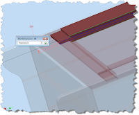
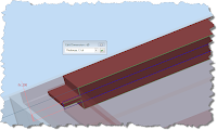
Should my value change for any reason, the slot thickness will update to reflect that. Here I've changed the Thickness to 1.5 inches (way to thick in reality, but it shows the update nicely). You can see that the slot thickness has changed appropriately.
Of course I could just build the slot, and type in '.250' to create the slot. After all, the math is pretty easy, right?
But what if the thickness changes? It's possible. Then I have to make sure that I remember to change the thickness of the slot to respect the '1/3rd rule' I've decided on.
Here's an easier way to remember that. Make Inventor do it!
When I built the part, I created parameters for Length, Width, and Thickness, among others. Here we're just going to focus on thickness, which is set to .750 inches
Editing the sketch that defines the slot, I can see that I've have it set to .250 inches, but there's no intelligence to it, I've just done math metally, and typed in the value.

(click to enlarge)
But, if I right click in the white field where the dimension is located, I have an option to 'List Parameters'.
If I choose this option, Inventor will show all the parameters that I've renamed from their default d(X) values.
I can now just select the parameter I want to build from, in this case 'Thickness', divide by '3', and I have that intelligence built in now.

(click to enlarge)
Should my value change for any reason, the slot thickness will update to reflect that. Here I've changed the Thickness to 1.5 inches (way to thick in reality, but it shows the update nicely). You can see that the slot thickness has changed appropriately.

(click to enlarge)
There you go! A little way to capture your design intent, and maybe for that, 'I must have forgotten to change THAT!' moment
Happy Inventing!
There you go! A little way to capture your design intent, and maybe for that, 'I must have forgotten to change THAT!' moment
Happy Inventing!
Tuesday, April 21, 2009
That's What Friends are For
With all the what's new in Inventor R2010, there's been a lot to keep track of. Definitely more than little ol' me can keep up with and post! Believe me, I've been trying.
Thankfully, there's more than myself just taking this plunge.
So I've pasted some links for some videos that the team has put together. I've watched some of them, (and even conducted one myself). Just watching my colleagues put up these recordings has taught me a ton!
Thanks to Mike and Javier! And thanks to Kanwar for being our narrator!
Inventor R2010 - What's New
Vault Workgroup R2010
Inventor R2010 - What's New + Sheet Metal
Note that we used gotowebinar to record this, and you may need to download and install their codec to see the videos.
You can get that HERE.
Happy Tuesday everyone!
Monday, November 24, 2008
Going out for a Joggle (revisited)
This is actually a repost of an older post that, well, needed quite a bit of revamping. I hope everyone finds this a better explanation than the last one!
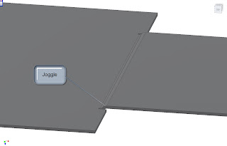
Creating a joggle in sheet metal isn’t a difficult task once you know how to approach it. The following steps will describe how to create a joggle using a combination of two different face tools.
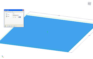
Step 1: Using the face tool, create your first feature.
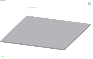
Step 2. Create a sketch on top of face completed in Step 1.
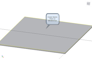
Step 3: Create a new rectangle (or other shape), on the plane, making sure to make one edge is colinear to the face created in
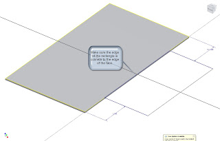
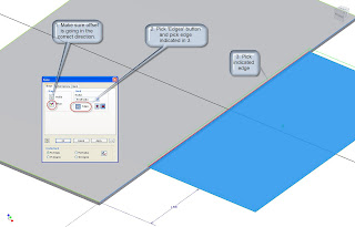
Step 4: Create a face using the sketch created in Step 3. Make sure you use the following settings:
a. The Face adds its thickness in such a way, it creates a step.
b. The Bend button is and the edge of the previous face is selected.
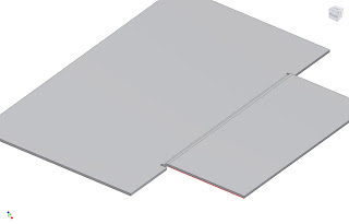
Hit Okay, and that will complete the joggle.
In other KETIV news! Our Industrial Designer, Kyle posted an Autodesk Showcase presentation on Youtube! Please take a look at the link HERE!
Creating a joggle in sheet metal isn’t a difficult task once you know how to approach it. The following steps will describe how to create a joggle using a combination of two different face tools.

Step 1: Using the face tool, create your first feature.


Step 2. Create a sketch on top of face completed in Step 1.

Step 3: Create a new rectangle (or other shape), on the plane, making sure to make one edge is colinear to the face created in

Step 4: Create a face using the sketch created in Step 3. Make sure you use the following settings:
a. The Face adds its thickness in such a way, it creates a step.
b. The Bend button is and the edge of the previous face is selected.


Hit Okay, and that will complete the joggle.
In other KETIV news! Our Industrial Designer, Kyle posted an Autodesk Showcase presentation on Youtube! Please take a look at the link HERE!
Labels:
Inventor Sheet Metal
Wednesday, October 01, 2008
I Prefer Perfect Perforations (in Sheet Metal)
First of all, thanks to everyone who came to the Autodesk Manufacturing Academy. It was great to see some old friends, as well as meet some new ones!

Here's an interesting little problem a user ask us during the sheet metal class (I'm sorry but I dont' remember the name!).
How can perforations be created on a sheet metal part in such a way that the geometry can be cut on a CNC machine of some type (laser, water jet, etc).
One of the simplest solutions would be to create a transparent texture that would visually show the perforations, but that doesn't give you any geometry that could be cut by the machine.
Another method would be to try to model the perforations and use a pattern to wrap them aroudn the folded model, but that could be tricky, and if the pattern gets to be large, could cause a performance issue.
Another option a bit of a marriage between the two options. You can create a folded model without perforations, but add them to the flat pattern using the modeling tools there.
The perforations won't show in the model, but you'll have them in the flat where the CNC machine will cut them.
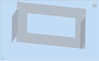
Here's the folded model.
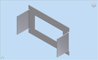
Here's the flat pattern, with some sample perforations added in the flat.
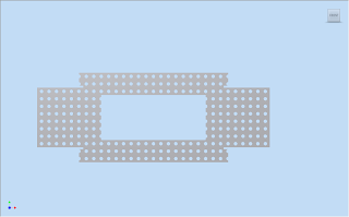
In this method, you achieve a balance between the need for and accurate part representation for the machine, while eliminating the extra effort of trying to maintain the pattern on the folded model!
And if you still want it, you can still use a texture for something representative on the folded model!

Here's an interesting little problem a user ask us during the sheet metal class (I'm sorry but I dont' remember the name!).
How can perforations be created on a sheet metal part in such a way that the geometry can be cut on a CNC machine of some type (laser, water jet, etc).
One of the simplest solutions would be to create a transparent texture that would visually show the perforations, but that doesn't give you any geometry that could be cut by the machine.
Another method would be to try to model the perforations and use a pattern to wrap them aroudn the folded model, but that could be tricky, and if the pattern gets to be large, could cause a performance issue.
Another option a bit of a marriage between the two options. You can create a folded model without perforations, but add them to the flat pattern using the modeling tools there.
The perforations won't show in the model, but you'll have them in the flat where the CNC machine will cut them.
Here's the folded model.

Here's the flat pattern, with some sample perforations added in the flat.

In this method, you achieve a balance between the need for and accurate part representation for the machine, while eliminating the extra effort of trying to maintain the pattern on the folded model!
And if you still want it, you can still use a texture for something representative on the folded model!

Labels:
Inventor Sheet Metal
Subscribe to:
Posts (Atom)


