Find us on Google+ Inventor Tales: General Inventor Topics
Showing posts with label General Inventor Topics. Show all posts

Monday, April 27, 2015

A Little Side Project Now Shared on GrabCAD - The NutPlate iPart

Every so often I like to create content just for the fun of creating it.

It does keep me practicing my Inventor skills, and sometimes, I just enjoy doing it.

One thing I've been doing over the course of the last few months has been creating some standard aviation style hardware.  I've created them as iParts, similar to I have in similar posts.

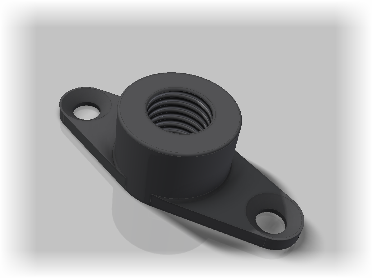
In this case, I've created a nut plate based on the part number NASM21047.  I found this data on the Coast Fabrication website, which I've found to be a great resource for these types of components

A sample of the nutplate iPart. 


I've created the parts using the same methods as in my post from a few months ago.  The steps are largely the same, so I won't recreate those steps here.  They're already in that post.

However, there are a couple of differences that are worth pointing out in this new version.

In this model, I've suppressed features in some of my iPart members.  This is because some of variations have a counterbore in the bottom, and others don't.  As a result, you'll see lines where the counterbore features, and the feature attached to them, are suppressed.

Features that need to be Suppressed for some family members can be added on the Suppression tab.

A Suppression Column.  I like to type out the words myself.

Suppression and compression of a feature by typing one of several values in the field.

Suppress a feature by entering one of the following:

  • Suppress
  • suppress
  • S
  • s
  • 0
Compute (turn on) a feature with one of the following.
  • Compute
  • compute
  • C
  • c
  • 1

I've also added a material column this time around, this makes sure the mass is accurate for each variation as well.

You can tell a column to be a Material column by right clicking on the header, and selecting the Material Column option.  Then type in the material you want in the field.

Notice the Material Column

Mostly, I just want to create a sample that you can use to get ideas how to create an iPart, or use this as inspiration to build your own iPart!

After all, why do the work if it's not going to be shared.  The iPart was built in Inventor 2015.

Take a look at the GrabCAD link here!  A login is required, but it's free! Download and enjoy!

Alternately, here's an another link to the iPart that doesn't require a login!

On one last note, I've done my best to make sure the dimensions are accurate, but there's always the chance I missed something.  It never hurts to check.

And if I missed something, let me know!  I'll do my best to correct it!

Sunday, February 01, 2015

Shimming Your Knowledge - Quickly Switching Commands in Autodesk Inventor

SHIM (noun) - A thin piece of material, sometimes tapered, used for alignment or support.

In my last post, I decided to create a series of short tips.  Things that I can create quickly, but also that end users out in "the wild" can find useful in their day to day jobs.

And for this post, here's a little tip that, one could say, is "small but mighty."

It's common knowledge to most Inventor users that right clicking and choosing either the Cancel (ESC) or OK keys will exit a command.  Hitting the Escape key on your keyboard will also exit a command.

Ok and Cancel two ways of ending a command.
You can also hit the Escape key.

But did you know that's not necessary?  Did you know that you can invoke a new command from the ribbon, or hitting the hotkey for a new command will not only exit the command, but start a new one?

You can just start a new command, which will end the current command.

Try it!  It works!

And to see a video demonstration, take a look below!


Friday, January 23, 2015

Shimming Your Knowledge- Changing Dimension Display in Autodesk Inventor.

SHIM (noun) - A thin piece of material, sometimes tapered, used for alignment or support.

I hectic schedule has required I take a different approach to my videos.

Instead of longer videos, which of course take more time to create, I'm going to create something shorter.  Originally I was going to call them "Microtips", but a friend suggested "Shims" as in the shims used in manufacturing.

But instead of using a these shims to adjust components for proper fir, you're shimming your knowledge for more productivity!

Now, let's use a this tip as a shim to adjust your knowledge for a better fit!

To start this out, here's one from the Inventor status bar, which is visible when a sketch is active, there are several buttons listed there, but for this tip, I'm just going to focus on the dimension display icon.

The dimension display menu expanded at the Status Bar
This icon changes how dimensions are displayed on your sketch, each providing you different information.

The options shown are as follows

1) Value - This option is the default for Inventor.  It shows the numerical value of the dimension, using the number of decimal places as set in the file's Document Settings.

Dimensions shown as value

2) Name - The Name options shows the name of the name of the dimension.  Notice that if a parameter is renamed, then that name is shown, instead of Inventor's default "dx" format.

Dimensions shown as name
3) Expression - This option displays both the dimension name, and the value at the same time.  If dimensions are linked to create mathematical expressions, these will be shown.

It also removes trailing zeros from a dimension, as well as showing additional decimal places for a dimension if it contains more than set in the Document Settings.

Dimensions shown as Expressions


4) Tolerance- If you've applied tolerances to a dimension, this setting will display the tolerances on screen. Additionally, any time a tolerance is evaluated at a value other than nominal, it will be underlined.  This is true of any dimension display setting.

For more on using tolerances in Inventor, see my earlier post!

Dimensions shown with Tolerances


5) Precise Value - This option removes trailing zeros from a dimension and showing the full decimal for a dimension if it exceeds the Document Settings.  It also shows the value of a toleranced dimension, even if it's being evaluated at a dimension other than nominal.

Dimensions showing Precise Value


And that's all for a short tip on Dimension Display!  I wanted to create something short and sweet.  I hope this helps!

I'm thinking of continuing to do this with the "little things" that are always a little hidden in Inventor.  If you think that's a good idea, throw in a comment below!

And a final note!  Here's a video describing the steps above!

Wednesday, December 24, 2014

How Much Can You Tolerate? - Using Tolerances Inside Autodesk Inventor Models.

“Tolerate, change, or be grateful.”
~Anonymous

The ability to create and evaluate tolerances has been around for several releases in Autodesk Inventor.  I actually can't remember when it was a "new" feature.

But it doesn't seem to get much notice.  I'm not sure how many out there know it even exists.

So I took a moment to put something together to show the steps to setup, and use, tolerances.

Before getting started, let me introduce you to the parts that are going to serve as our samples.

I've created a sample lever and shaft.  Similar to what might be seen on a carburetor butterfly valve, although it's really just a sample.
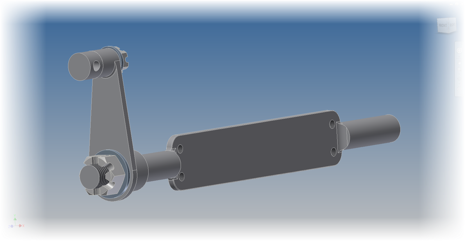
The sample for this post

With the stage set, it's time to face the next question, where to start?

The first way of adding tolerances to an Inventor model is similar to what you might do on a good, old fashioned, title block.  That step is to add tolerances per the number of decimal places as a title block.

Tolerancing in this fashion is found from Tools>Document Settings, on the Default Tolerance tab.  Here different tolerances can be set for a different number of decimal places.
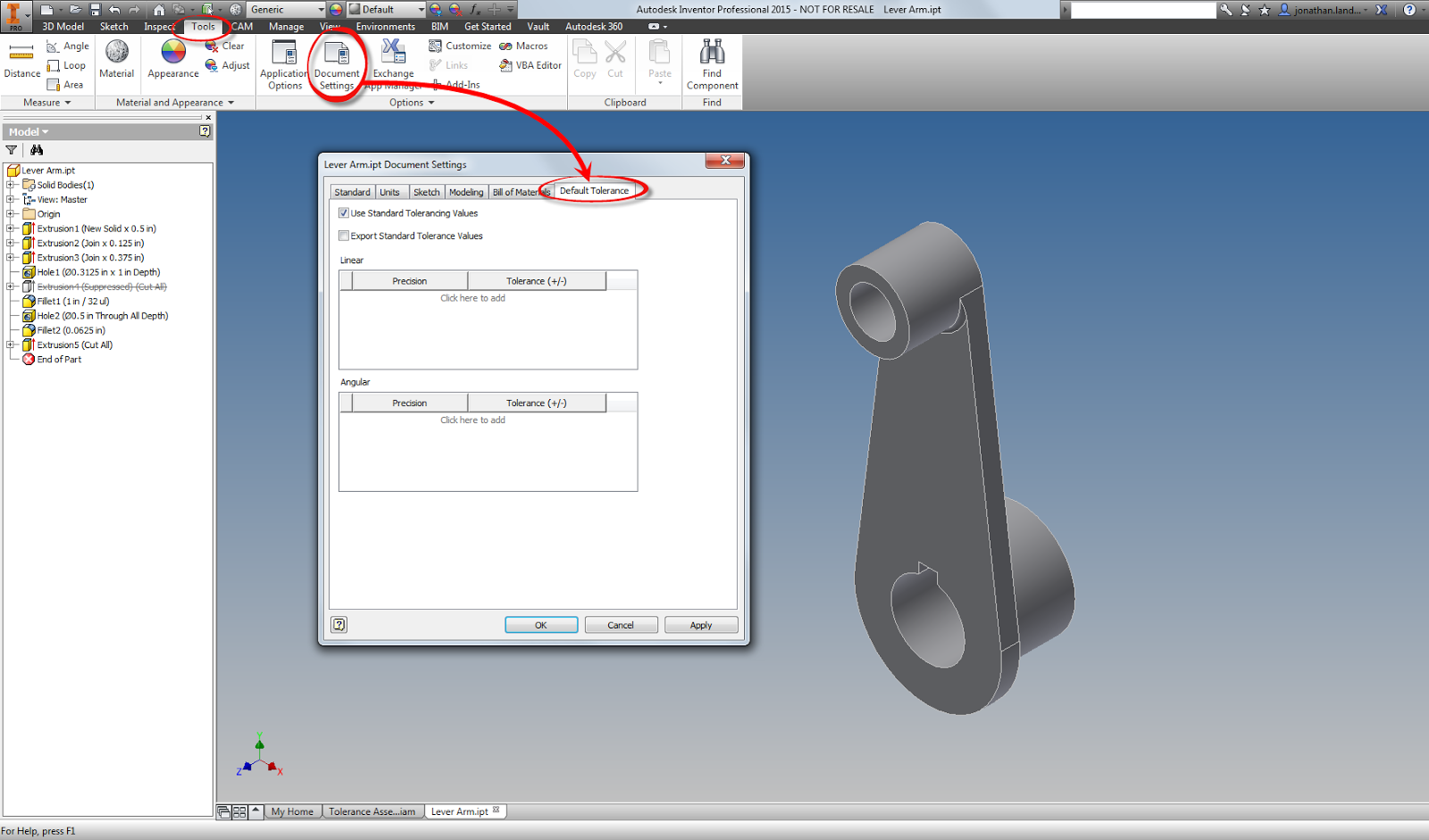
Locating the Tolerance Values for a part.
For this sample component,I'm going to set tolerances as follows.
.
.00     = . +/-.015 inches
.000   =   +/- .005 inches
.0000 =   +/- .0005 inches
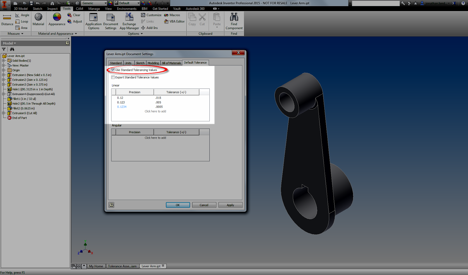
Adding standard tolerances.  It's almost like a title block!

Once these are set they will display on the modeling screen.  Different tolerances can be applied to different modeling dimensions by editing, and right clicking on a dimension and choosing Dimension Properties. .  Here the tolerances can be set by changing the dimension to match whatever the desired model tolerances are.
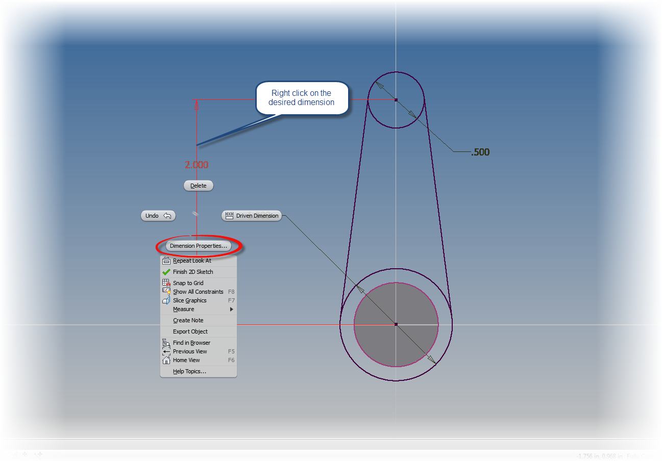

Right click and choose Dimension Properties

Setting a tolerance via a standard tolerance.

However, there are plenty of other cases where special tolerances must be used, such as deviation, limits of various types, or any other tolerance that may not fit the default tolerances for the model.

To "fine tune" tolerances by adding a special tolerance in a sketch first edit the sketch.  Once the sketch is being edited, use the same as we used before.  This time, use choose the type of dimension to be placed with the flyout.
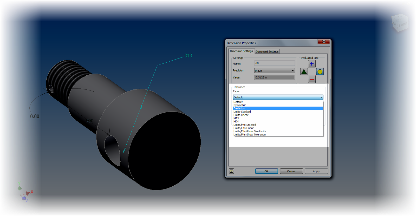
Choosing a dimension type


If you're trying to add tolerances to dimensions for a hole feature, edit the feature, and left click on the arrow next to the dimension you wish to add a tolerance to.
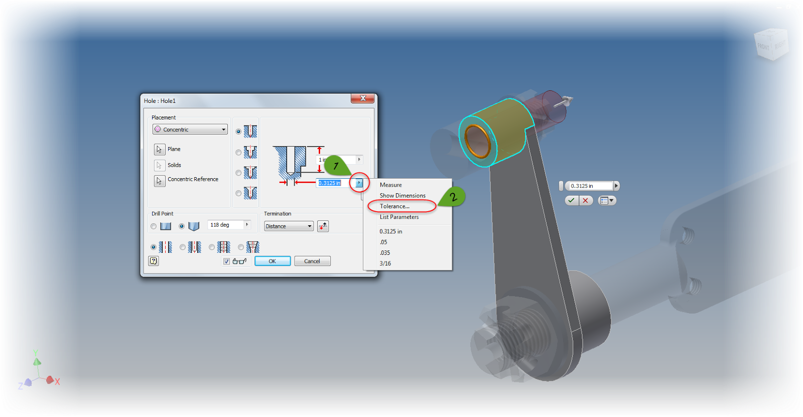
Setting the tolerance on a hole feature.

Now a tolerance can be added just like the sketch dimensions.
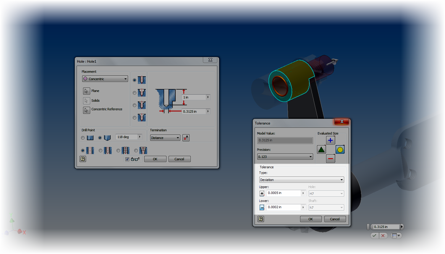
The tolerance is set with a deviation tolerance
But what if you want to change the tolerance on something like an Extrusion or Revolution?  If you take the time to check, neither of the previous tools will work.  So how do you add a tolerance for those features?

Don't worry, there's still a way.  On the Manage tab, edit your Parameters.  All the dimensions for the part are shown here, and by choosing the arrow next to the dimension (similar to what we did in the hole feature), the tolerances for any of the dimensions driving the part can be changed.
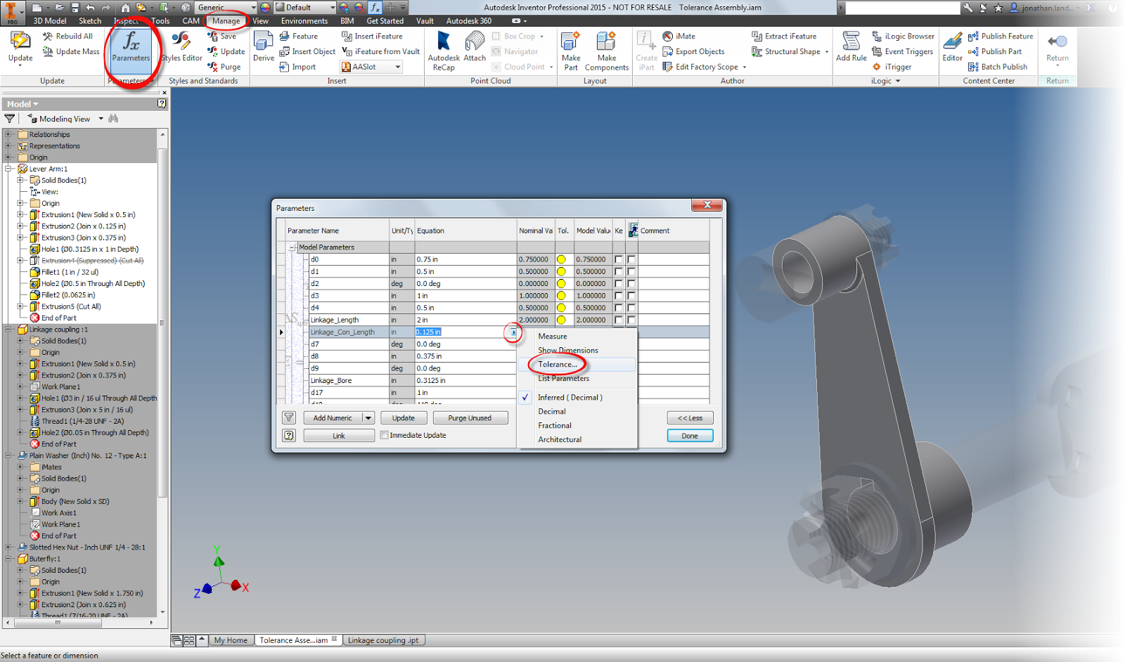
User Parameters to set tolerance

So now tolerances have been added to the desired dimensions.... So what?  How can the limits of the tolerance be evaluated?

In each of the tolerance dialog boxes, and in the Parameters screen, there are four icons that change the size of the feature, based on the tolerance you choose.  The available options are upper, lower, median, and nominal.


For example, let's evaluate the pin and it's mating hole at it's maximum material conditions (smallest hole diameter and largest pin diameter).

To do this, edit each part in turn, and add the desired tolerances.  I'm going to use deviation tolerances, since I always found these to be the hardest ones to evaluate by hand.

After changing the tolerances in each feature, I'll set each feature to evaluate at the maximum material condition.  For the shaft, this is the upper side of the tolerance, for the hole, the minimum.
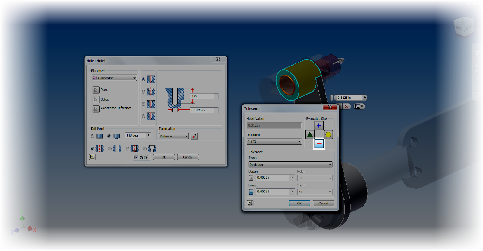
Choosing the smallest possible tolerance dimension

Choosing the maximum tolernace size for the shaft.
With these values set, I can return to the assembly level, switch to the inspect tab, and run an interference check.
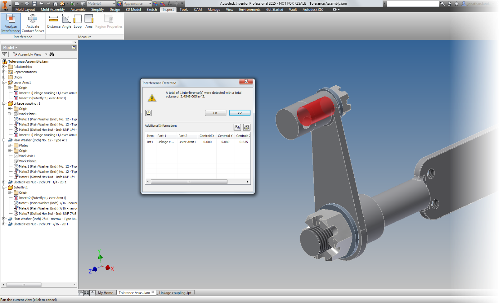
Even though the parts are in tolerance, there's an interference


In this example, there is an interference that lays well within the acceptable tolerance I've created.

So what does that mean?  There's work to do?  The nominal sizes and tolernances will have to be adjusted so they don't interfere under any size that still lies within the range of the tolerances.

And what does this mean for everyone else?  

Take a look at tolerances in Inventor, and see how it can help you.  It's always cheaper to find the mistakes in the computer, than in the shop!

And finally, a couple of  "Pro Tips".

There's a couple of small tricks I learned as I worked with tolerances, so I'm going to add them here.

1. Rename parameters.  When setting tolerances, especially when using the Parameters screen. It makes it easier to know which dimensions and parameters you want to change!  There's a tip on how to do that in "Tips for Short Attention Spans".
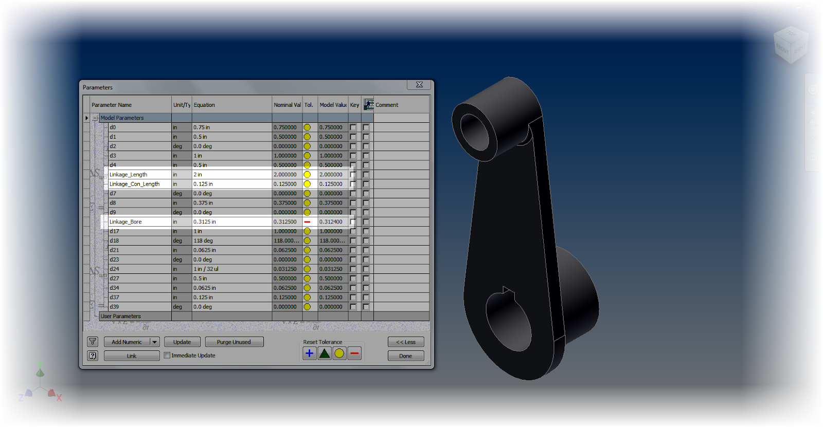
Using named parameters

 2. Use the Document Settings "Modeling Dimension Display" to set the default dimensions for your model.  Any dimension placed will take this number of decimal places, and by default, the tolerance associated to it.
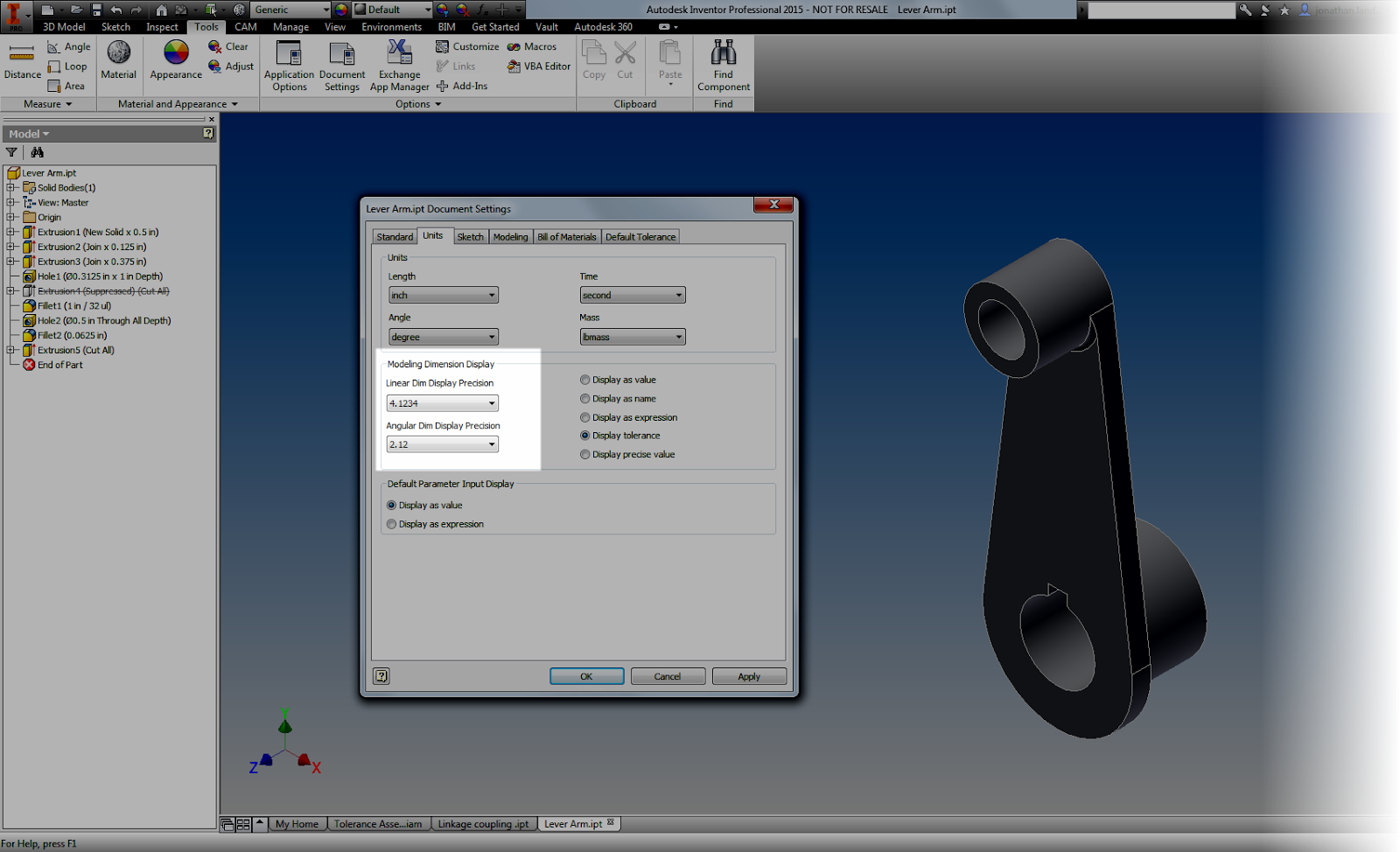

Choosing the tolerances
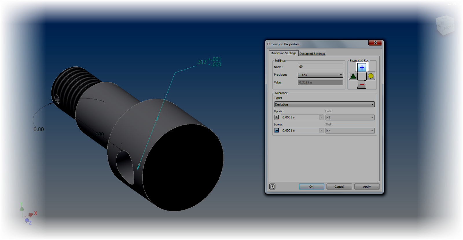
4, Change the precision of an individual dimension.  One option when editing a dimension's property, there's an option to change its display value.  This can make sure that you can see an accurate value for the dimension.
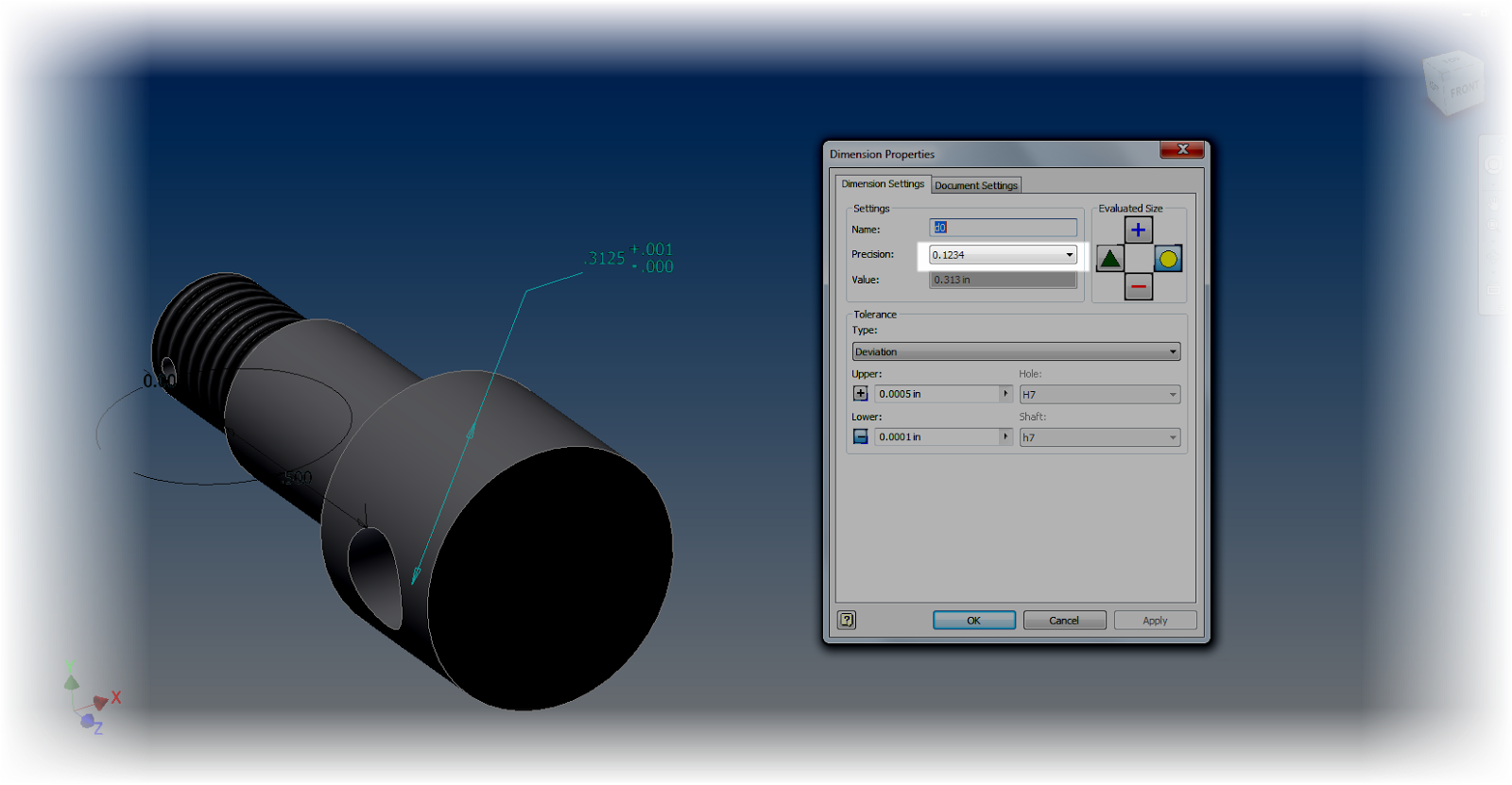

Changing the precision of an individual dimension


5. Use the dimension display options to your advantage.  Changing the dimension display will change how your dimensions show on the screen, and can make sure you get an accurate result.
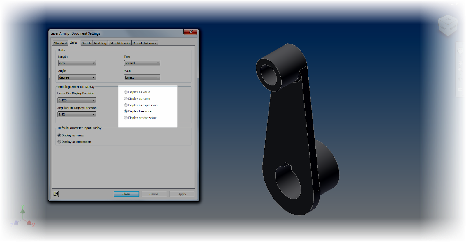
Add caption

For example.  Using "Show Precise Value" will show exactly what the dimension's current value is.

An underline under the dimension indicates that the dimension is currently being evaluated at a value other than its nominal value.  In other words, it's set to be evaluated under one of it's tolerance values (maximum, minimum, median).


6. Explore the tools!  Many of the different tools and dialog boxes share common tools and dialog boxes.  Use that to your advantage.  You can access Document Settings from Dimension Properties for example.  You can change the Evaluated Size of a dimension from the individual dimension properties, or from  the Parameters screen, or from the Dimension Properties dialog box.

And if you've got a sketch active, you can change the dimension display from the dialog box!  Take a look!
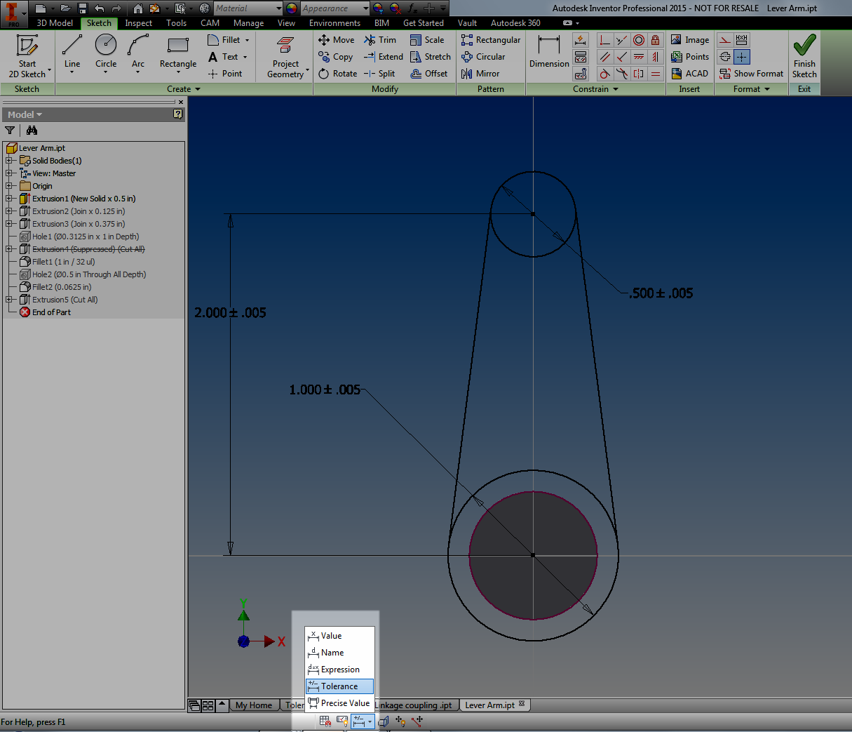

Changing Dimension Display.

Whew!  This post did end up being a lot longer than I had planned.  But I hope you find the info valuable!


Tuesday, November 25, 2014

A Use for Inventor's Sketch Constraint "Relax" Mode

“Try to relax and enjoy the crisis.”
 Ashleigh Brilliant 

Sometimes, it takes the right circumstances to find a good way to use a new feature in Autodesk Inventor.

The new Relax mode in Inventor 2015 fell squarely into this bucket.

When it first came out, I was frankly a little unsure of the new tool.  It's my nature.  I just find myself wary of any tool that is "too automatic".  I'm just type "A" enough to not like it when too much is done for me.  I circle them like a cat sizing up a potential meal.

But I've also learned that there is a time and a place for these tools too.  Experience has taught me to never dismiss a new function too quickly.

In my case, I was rebuilding an aircraft instrument panel in Inventor.

Originally, I had created it as a test to benchmark how text affected the speed and file size in Inventor.  To do this, this, I created the cutouts for the instruments as extruded borders with text inside.

A sample of the original panel.  There were no cutouts for instruments,
but this was part of a test and not meant to be "real" at this point.
Not accurate as a part.  But perfect for the benchmark I was creating!

But once I had done that, I wanted to create a more accurate representation of the panel.  This meant deleting the extruded  borders, and recreating them as cutouts.

But as I did that, I ran into one issue.  Part of the sketch that I had removed had anchored the text that I had placed.  Now the geometry was disassociated.


I could delete and recreate the sketch, but I didn't want to try to retype all that info again.

But what I did find was able to delete constraints to free the geometry and reattach it to other geometry,  In some cases, this meant deleting four co-linear constraints, and recreating them all over again.  This is what I would have to do with these circuit breaker cutouts, for example.


While it wasn't a huge pain for a few of them, there were a ton, there was a lot to do, so how could I make this task go a little quicker?

Well, if you guessed that I used the "Relax" constraints mode that's new to Inventor 2015, you would be guessing correctly!

First, while editing the sketch in question, I  turned on Relax Mode,  It can be found at the status bar on the bottom of the Inventor drawing screen.  You can also use the hotkey "F11"


Once that was on, all I had to do was grab the text and drag it.  The constraints would automatically be removed, and I apply the new sketch constraints right away.


Is it a small thing?  Perhaps.  But over time, it did make fixing the panel a lot easier!

A simple thing?  Perhaps.  But it can be the simple things that matter.


Thursday, November 13, 2014

Did You Know You Can Use the End of Part Marker to "Compress" an Inventor File

“The question is, what's the best way to do this? There may not be a one-size solution to the question.”
 Peter Gore

Today I wrapped up some basic benchmarks for extruded text versus sketched text in an Autodesk Inventor part model, and I was getting ready to e-mail them out for some testing on external systems.

First, what did I use for the test?

The files I created were from an instrument panel for light sport aircraft from the RV series.

I recreated the panel from an image, and created the instrument identification first as extruded text.

The panel with extruded text

In the next panel, I created a panel with the same text, but this time, the panel the text was created as sketches, and not extruded into 3D extrusions.

The panel with sketched text.  You can tell by the projected sketch lines, which are magenta.

The challenge?  The panel with the extruded text was nearly 13 MB!

12.7 MB.  That's big! 
By comparison, the panel using just sketches was less than 2 MB!

1.64 MB.  Nearly a tenth the size!

First, let's take a moment to ponder that.  If you're creating a lot of text, consider leaving it as sketches. These two models show a big difference in the size, and that can affect performance, especially if there's a lot of them.

But there was also another challenge I was facing.  How can I e-mail the files?  Together, these files are flirting with 15 MB.  That's big enough to cause problems with some e-mail systems.

Sure, I could zip the files, but there's another way to "compress" an Inventor file.

Locate the End of Part marker.  It's also known as End of Folded if you're using a sheet metal part.

Right click on the marker and choose Move EOP to Top (or  Move EOF to Top for sheet metal parts).

Locate the End of Part marker.
This pushes the marker to the top, and all the a feature in the part are suppressed.

The EOP at the top, and the features suppressed
After compression, the part with extruded text was a mere 2.41 MB.

A big change from 12.7 MB

By comparison the panel using Sketches was 1.01 MB.  Not as drastic as the larger file, but substantial nonetheless.


A smaller change, but still about a third. 
Having that trick can make it much easier when moving large part files back and forth.

When the recipient gets the file on the other end, just right click on the EOP/EOF marker and choose Move EOP/EOF to End.

How to get it back. 
This can be a nice way to "compress" an Inventor file without having to use zip files.  So when you're sending part files around, take a look!  It's worth a glance.

Oh!, And if you have an unsuspecting coworker, rolling the EOP to the top of their part when they leave their computer unattended has been known to be an "April Fools Trick" in the past.

Not that I condone that..... Or I've ever done that....

*************************Edit 17-November-2014*************************

Thanks to Clint Brown of Cadline Community for sharing a nice bit of iLogic code that will rollup the EOP marker and put it in an email for you.

It's definitely work taking a look at!

Have a look by clicking here! 


Monday, November 03, 2014

How Precise is Precise? Changing Measure Precision in Autodesk Inventor

“Most of the most important experiences that truly educate cannot be arranged ahead of time with any precision.”
Harold Taylor

KETIV's AMA 2014 in Southern California is a wrap!  It was good to see everyone, and as much stress as it was preparing for the session I helped in, it was fun presenting again.

But out of that course came one question that I didn't know the answer to.

"How can you change the default measuring precision in Autodesk Inventor?"


The default measure location behavior
At the time, standing in front of the room, I didn't know the answer.  After all, I don't know everything!

But over the weekend, the thought would occasionally return to me.  I felt like there might be a way.

Finally, I had a little bit of inspiration, and decided to give it a try.

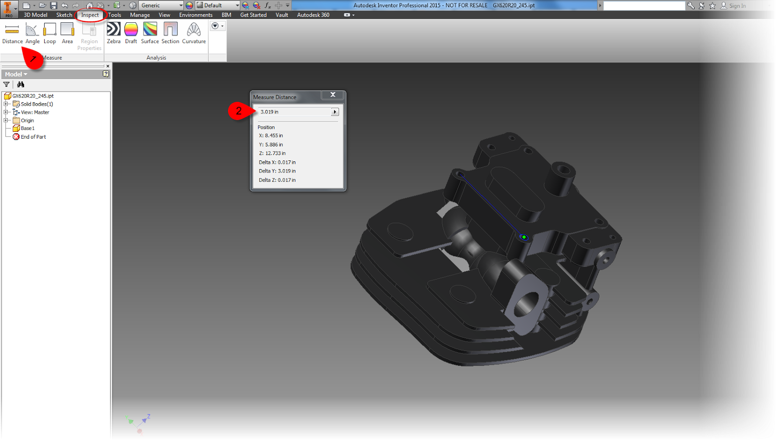
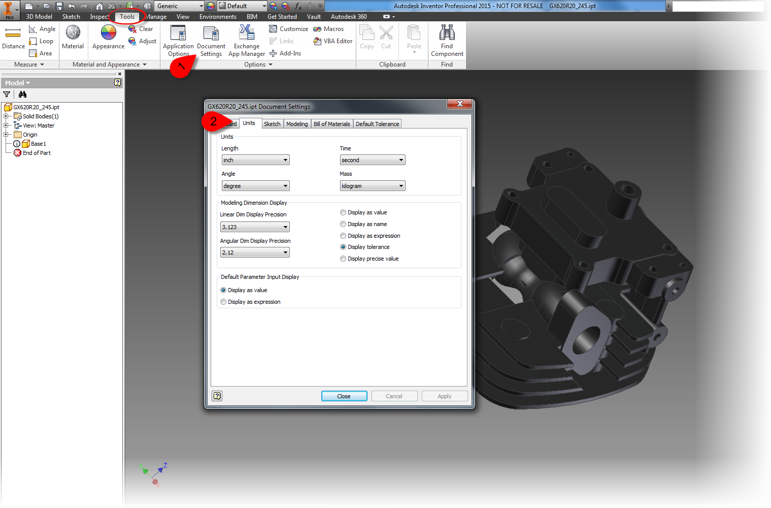
Opening up Inventor, I played a little bit of a hunch.  On the Tools tab, I located Document Settings and opened up the Document Settings dialog.

Using Document Settings


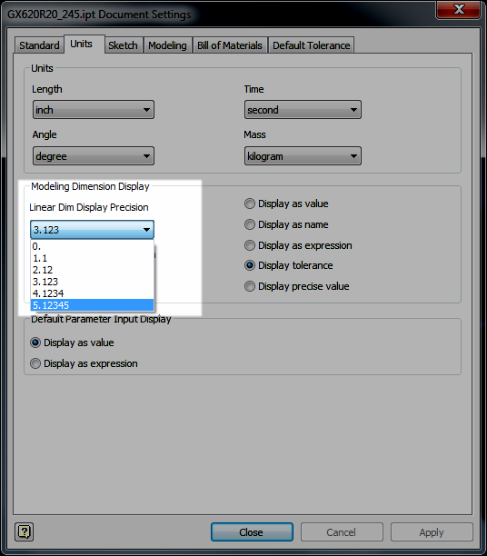
Once on the Document Settings dialog,choose the number of decimal places you want by changing the Linear Dim Display Precision (or angular if that's your preference).

Changing precision

Once that's done, the measure precision will change for this document.

Precision reset. 

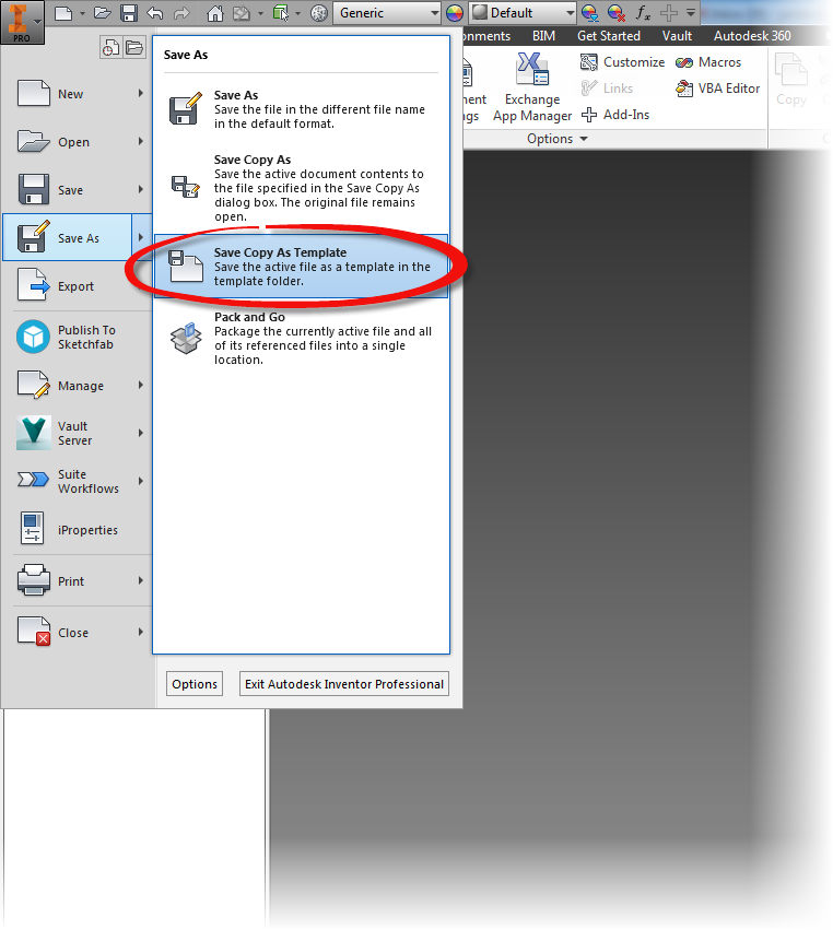
But wait, I said default setting, right?   If you want to make this a default behavior, the final step would be save these settings into a template file.

One way would be to open the templates from their location, make the very same change, and save that file.  This would change the existing templates.

The other would be to start a new file, make any changes you want, and choose the Save Copy As Template option.


Save as a Template

Whichever you choose is up to you!

On a final note.  I know that there are those who might want a different functionality.  And that's okay!   Share your ideas on the Autodesk Inventor Ideastation!

Sunday, October 26, 2014

Scroll Wheels in Autodesk Inventor and AutoCAD. They can behave the same!


As the Autodesk Manufacturing Academy (AMA) gets closer, I find myself pretty busy.  But I still wanted to share a tip, even if it's short.

Here's a simple tip that sometimes comes up when I'm training my Inventor Essentials class.  It's most often encountered with users who have to constantly switch between Inventor and AutoCAD. 

"Can scrolling in Inventor and the scrolling in AutoCAD made to match?"  

That's right, by default, Inventor and AutoCAD don't scroll in the same direction.  I've been told that's because one program views the geometry as moving toward the camera (or user), the other one views the camera (or user) moving toward the geometry. 

I don't know if this is true or not.  But it at least sounds good. 

More importantly, there's a way to make them work the way an individual user (that means you!) can make each program match. 

First, in AutoCAD, type ZOOMWHEEL.   

Change the setting to 1 or 0.  Use whichever suits your preference. 

Type ZOOMWHEEL in AutoCAD

Now, in Inventor, go to Tools>Application Options>Display

Locate Zoom Behavior, and set that to the preference you like. 

Changing zoom behavior in Inventor

Everyone is a little different, but between these two variables, you can get them to do what you want, and get them to be consistent about it! 

In the meantime, I'm back to getting ready for AMA!