Find us on Google+ Inventor Tales: Inventor Assembly Topics
Showing posts with label Inventor Assembly Topics. Show all posts

Monday, March 31, 2014

Setting Component Materials Upon Import in Autodesk Inventor

“Finding the material wasn't a problem — remembering what to look for was.”
 Steven Severin

A question was posed to me earlier this week.  I'm importing files of different formats into Autodesk Inventor, but I need the material to be Mild Steel, instead of default.

Is that possible?

I wondered for a moment.  I looked around, and thought "what if I change the material in the standard.ipt template?"

It made sense.  Inventor starts with that template, what if the imported files made a pass through that template first?  There was only one thing left to do.


Try it! So the first thing I did was browse to the directory containing the standard.ipt template file, and open it directly. 


Make sure to open the file with the open command!  Do not create a new file from the template!  The material has to be changed in the template file, so when a new file is created from it, the material is already set.


Once the template file is open, it's time to choose.  In this case, I'm using Mild Steel.


Once it's the active material, I save the file and close it. 


Now that my template has Mild Steel set as the material, I can import the files that I need.  In the example here, I'm using Solidworks files that I've downloaded from GrabCAD at the link here.


The files will translate, and Inventor will now use the template to apply Mild Steel to the Imported Parts.

Checking the Bill of Materials screen in Inventor, I can see that indeed, all the materials are set to Mild Steel.


Now there are a couple of notes.

This option sets everything to Mild Steel.  Anything using this template will start with Mild Steel, so this may not be the perfect solution for everyone.

But it can be useful, and it's pretty quick to change.  So think about it, give it a try, and see what it can do for you!

And be sure to check out the video version below!


Friday, February 07, 2014

Linking Presentation File Colors to Assembly Colors in Autodesk Inventor

“Our work is the presentation of our capabilities.”
Edward Gibbon


Every day, computer software gives me challenges.  Sometimes there small, simple things.

Sometimes they make me feel like Indiana Jones when he's getting chased by that giant boulder in Raiders of the Lost Ark...


This challenge probably fell somewhere in between.

What was the challenge?  How do you get Autodesk Inventor presentation file to match the colors in the assembly, even when the colors change? 

It's actually not very difficult, but there is a trick to it.

When creating the  presentation, make sure to click the Options button, pick a View Representation, and choose "Associative".

Locating the Options to link the views.


By choosing this option, the view in the presentation will now follow the view in the assembly!

If the option is left unchecked, the presentation file colors won't change as the assemblies colors change.  They will be independent.

For the full tour, check out the video here!


One thing I can't say I've found, is how to change it after the fact.  Once committed, it remains the way it is.

If those of you out in the 'Verse out there have found a way, throw out a comment below!

And one last note!

I used view representations I created in this post.  If you're interested in learning more about creating view representations, I have a post for that I created a few years back here.  Take a look! 


Wednesday, February 05, 2014

A Guest Video - Top Down Design from TheCADSetterout

“(The wins) give us a lot of momentum. We're on top right now, and nothing can bring us down.”
Jamee Juarez

This year, I wasn't able to make it to Autodesk University 2013.  Scheduling with class, work, and budget all conspired to keep me away this time.

I was very disappointed that I couldn't attend.  There was information I missed, and people I didn't get to see.

Fortunately, the classes are becoming available online, so I can at least get the information, if not raise a glass with my friends and colleagues!

One great class that I that is now offered online is MA2604: Drive Inventor with the Top Down: Alternative Assembly Modeling Techniques by Paul Munford of The CAD Setter Out

This video is very informative, and well worth watching.  I've already added it to my favorites!  Take a look at it below:


Be sure to check out the other classes that are available too!

Wednesday, January 15, 2014

Controlling Component Participation in an Assembly Level Feature in Autodesk Inventor

As an artist, I've always wanted to participate in the dialogue of art with other artists.
Jeff Koons

I've always considered assembly level features a bit of a specialty tool in Autodesk Inventor.  That doesn't mean I don't think it's a valuable tool.  It just means that it seems like there are users who really use it, and there are users who never touch it, with very little middle ground.

When I'm playing around with wood working projects, I use it a lot.  It's perfect for creating things like dowel holes and hinge slots.  These features are typically creating in components that are already assembled together in wood working.

 Today, I was slowly building a Pie Safe in Inventor from plans I found in a Fine Woodworking article, and the time came to add the hinges to the doors.

A 'Quickndirty' rendering I created in Autodesk Showcase

The hinges need to have clearance cut for them, which is pretty common, even expected.

A typical hinge pocket.
Image courtesy Fine Homebuilding
 Since the door would be assembled by this point in the construction, I reached for my assembly feature, created my sketch, and extruded my cut.

And something happened I had forgotten about.  Inventor cut the slot alright!  But it cut right through the hinge too!  The assembly feature cut everything in it's way!

Doh! That's not what I wanted!

At first glance, one might think that this tool isn't very helpful if it's going to blindly cut everything that gets in it's way.  But Inventor does give us the ability to control what the assembly feature cuts.  All that's needed are a couple of clicks.

The first thing I need to do, is locate the assembly feature in the browser.  Expand it, and a list of the components that are "participating" in the extrusion appear.  In this case, it's the component making up the edge of the door (2013-22-27:3) and the two hinge leaves (Generic Hinge1:1 & Generic Hinge2:1).

Components participating in the feature


 What I really need to do is tell Inventor not to have the hinge leaves participate in the extrusion!

I do that by selecting each hinge leaf, and choosing "Remove Participant". 

Removing the participants


Once the hinge leaves are removed from the feature.  Everything looks as it should!  My design intent is truly captured!


So that's how to tell Inventor not to include components in an assembly level cut.  If you're using this tool, I think this could be an important aspect that could get easily overlooked. 

And as one last tip, what if a component needs to be added to the assembly level feature, that is told that it needs to participate?

If that's the case, right click on the feature, choose "Add Participant" and select the components you wish to add.  Give it a try!

Participants can also be added to an assembly level feature

And for a video on the steps I showed above, take a look below!


And one final note, more information on the assembly level feature can be found in the Inventor help system here!

Sunday, September 29, 2013

Using the Mirror Component Command in Autodesk Inventor

“Only in quiet waters do things mirror themselves undistorted. Only in a quiet mind is adequate perception of the world.”
Hans Margolius 

In this weeks post, I chose to visit a tool that's been around a while, but I think doesn't always get it's due. 

That tool, is the 
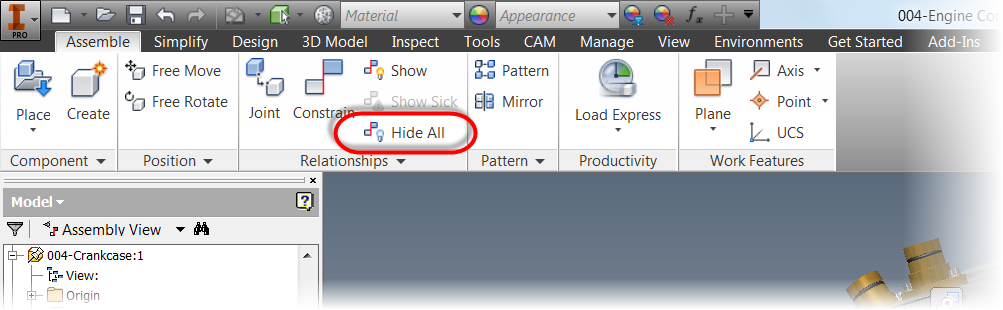
Mirror Component command in the assembly file. 


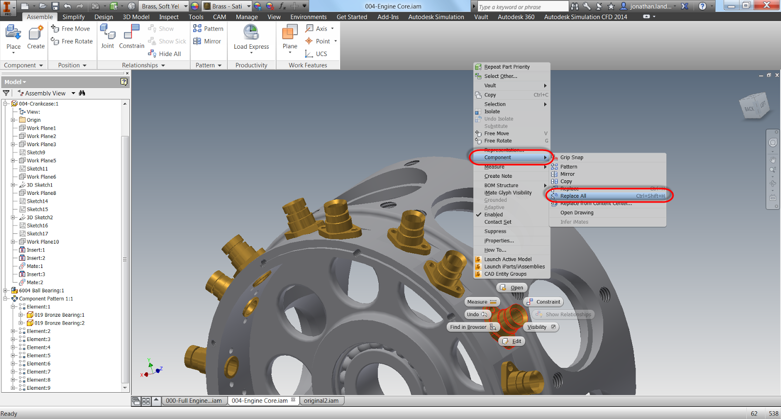
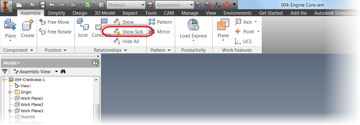
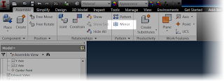
Locating the mirror component command


This tool will create opposite handed components, using another component for reference. 

I could go on talking about theory, but instead, I think I'll use an example of where I used this function.

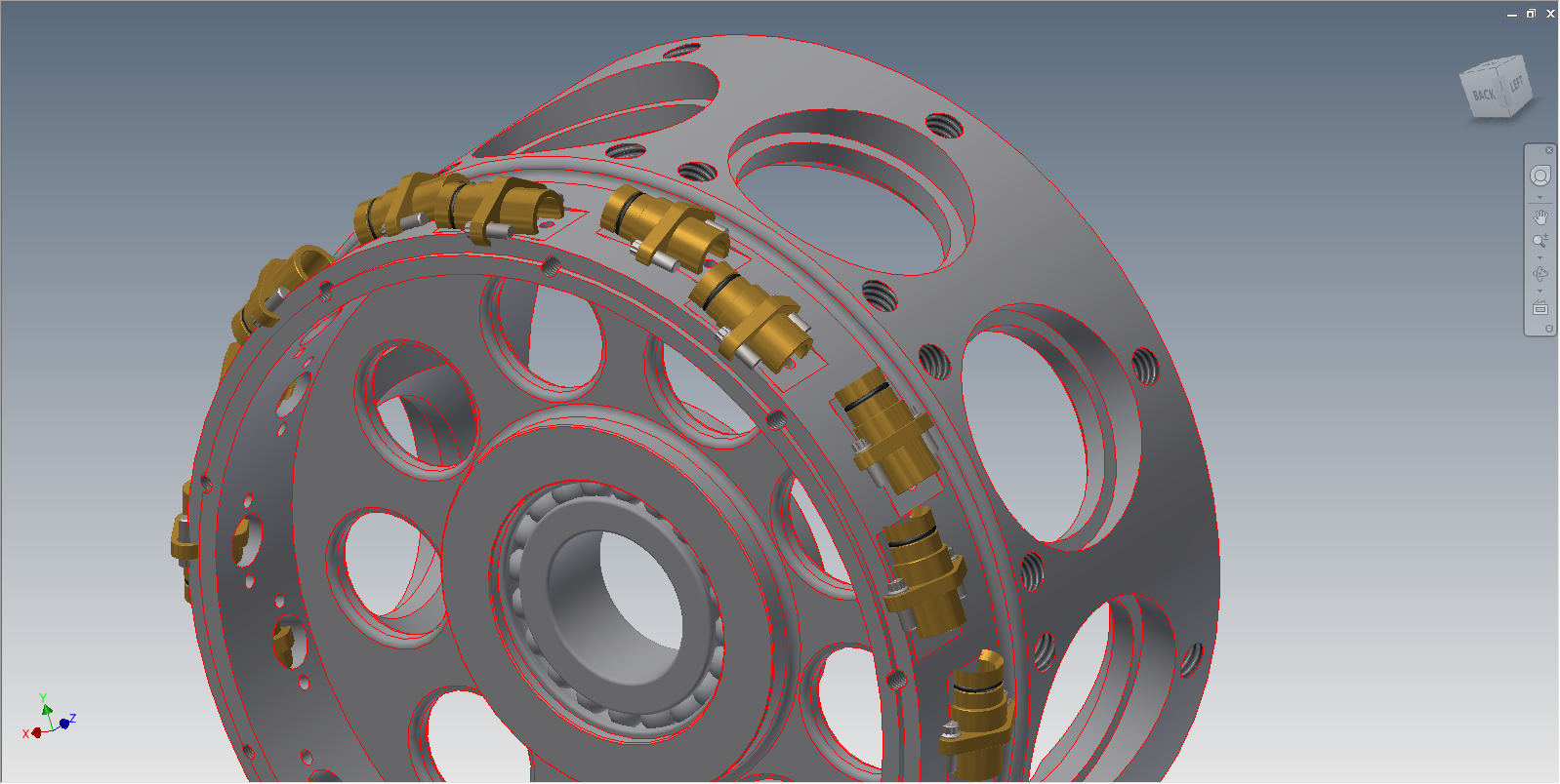
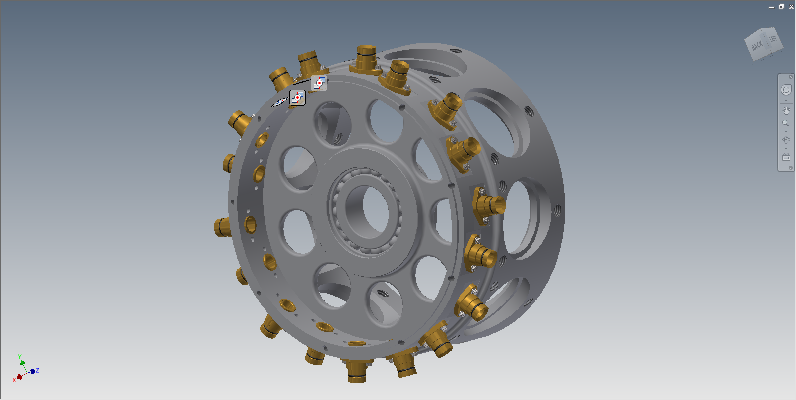
Over time, I've been slowly rebuilding a 9 cylinder radial engine I found on GrabCAD.    Most recently, I was working on the rocker arms in the engines valve train.

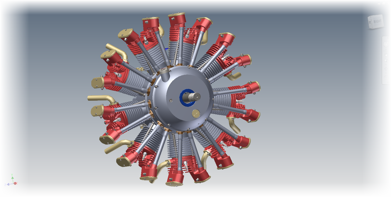
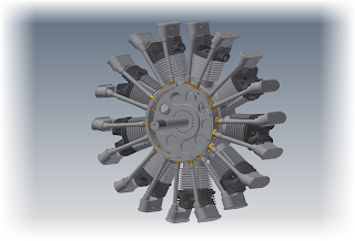
The 9 cylinder radial in it's current stage of completion


I first created the rocker arm for the exhaust side, which was a bit of a challenge.  The arm has an interesting twist in it that's required to make it work.

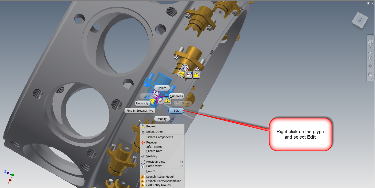
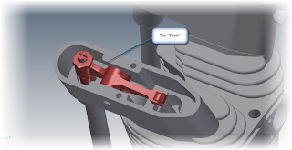
The Rocker Arm in Position


Needless to say I wasn't excited about repeating the same for the intake side.  That is, until I realized the intake rocker arm is just a mirror image of the exhaust side.

That makes it a whole lot easier!


First, in order to make things easy, I isolated the rocker assembly.  Notice that I'm still working in the assembly the rocker is placed in.  That's indicated in the browser below.


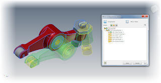
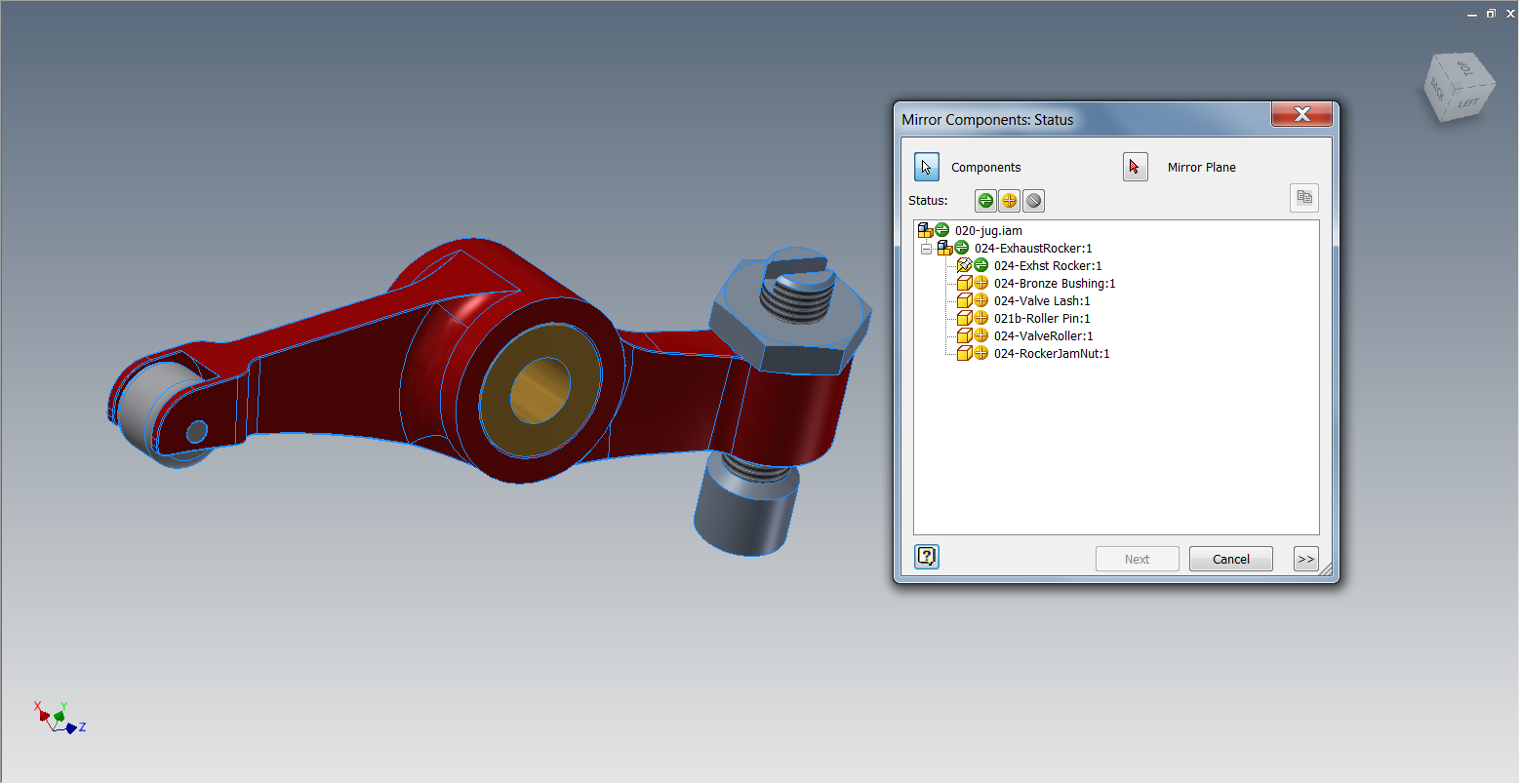
So instead of rebuilding the entire intake side from scratch, I just selected the Mirror Component, selected my rocker assembly and got started! 

The first thing to note are the status icons.  The green icon indicates the subcomponent will be mirrored, creating a new subcomponent in the process.  The yellow icon will reuse the existing subcomponent, and won't create a new subcomponent.  The gray icon indicates that the subcomponent will be ignored, and not used at all.


By default, Inventor wants to mirror everything.  While every situation varies, in this case I only need to change the rocker arm, so I can reuse every other subcomponent.

Selecting each component in the dialog box allows the status of each subcomponent to be changed.


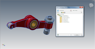
The components selected for change.
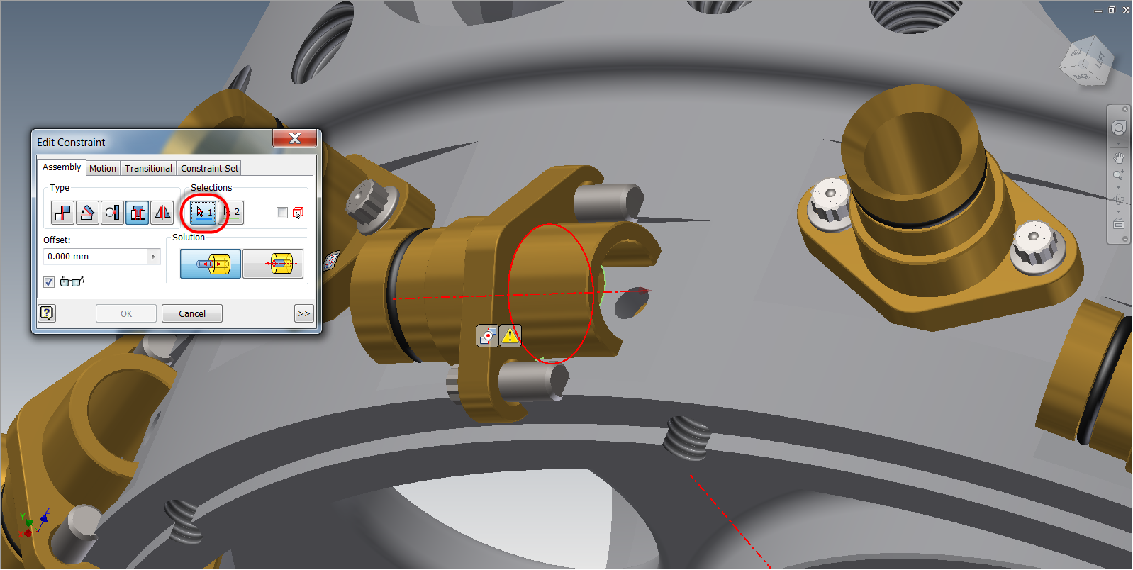
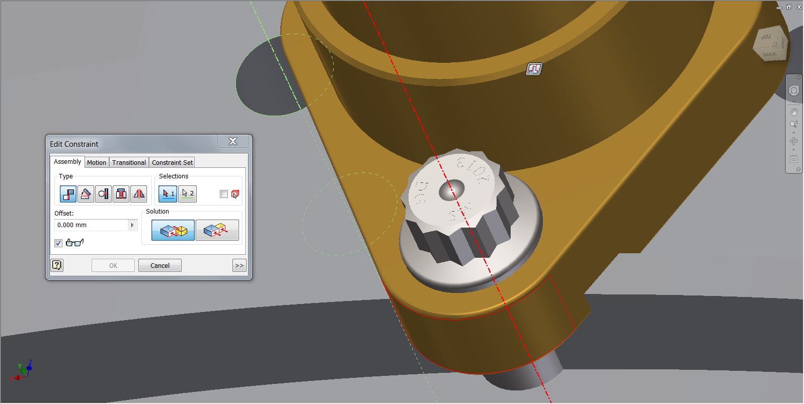
Now, I just have to select a plane to mirror about.  This can be a workplane, or a flat plane on the part.  In this case, I just chose the side of the bushing. 

I can always reposition with assembly constraints later!  Also, notice how the mirrored subcomponents are colored green in the preview, and the reused subcomponents are colored yellow.  That's good feedback!


Previewing the mirror

I'm almost there now.  With everything the way I want it, I can click next in the dialog box.   I'll have the ability to rename the new files here (which I've done).  I can also choose if I want Inventor to open these files in a new assembly, or place them in this one.

In this case, I've already renamed the files, and selected the option to place them in the existing assembly.


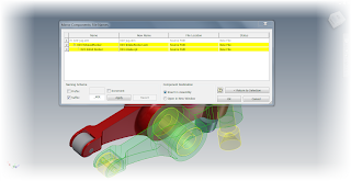
Renaming the components
 Now with all my options set, I can click okay to create the new component.


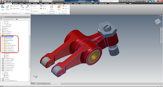
The new rocker highlighted, and show in the browser.

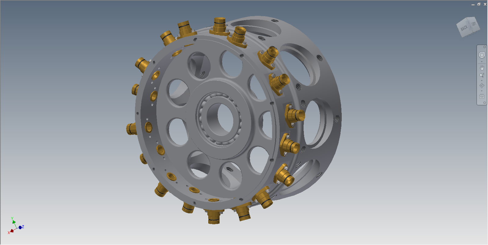
Now the new rocker is placed in my assembly, now I can turn the visibility of the other components back on, and position the rocker in the assembly. 


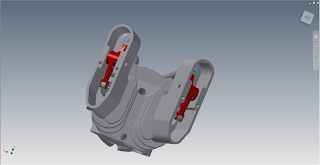
The rockers in position.
So there it is!  An example where the mirror component tool really helped me out. 

So take a look at it and see where it might be able to help you! 

Acknowledgements:


This file was not created by me.  It was originally created by Dave Goetsch on and shared on GrabCAD here.

I'm only recreated what he's shared in Inventor.  The major credit goes to Dave!

Other notes:

You may realize that I'm not creating videos as often as I used to.  That's because I'm in the process of taking classes in the evenings, and I quite simply, don't have the time I used to.

I'm hoping to revisit these blog posts with videos later!  But rather than hold up the show, I decided to place them in text only. 

Enjoy!

Wednesday, August 21, 2013

Updating Part Features from Assembly Features with a Neat Little Utility

“I don't think we're considering a lot of changes.”
Nick Saban

In my last post, I talked about a utility I found on the Autodesk Exchange Apps website for migrating assembly level features to parts.

I like the little app, and I've decided it's got a home with my Autodesk Inventor installation for the foreseeable future. 

While on a business trip the early part of this week, I was messing around on my laptop and found another feature I like about this app.

The ability to update the migrated part features from the assembly!

Here's how it works!

First, I'm going to open my Feature Migrator by clicking the icon on the Tools ribbon.  This can actually be done at any point in the process, but I'm going to get it out of the way!

Starting up the Feature Migrator
.
Taking a look at the files I used my previous post, the slot migrated from the assembly to the parts is seen.  The assembly feature is currently suppressed, which was done by the migrator when it first created the part features from the assembly feature.


The suppressed feature


But now, I'm going to update the assembly level feature, and use it to change the part feature it created.

First, I need to unsuppress the assembly feature by right clicking on it, and unchecking Suppress.

Right click to unsuppress the feature


Now, I can edit the assembly feature just like I always have.


Editing the sketch


Finished editing the feature

Once the feature is edited, I can now Open the parts that are affected by the feature.  Note that it's important I open the part in a separate window, don't edit the component in place.

Opening the component to update

 With a component open, the Feature Migrator will show the feature created in the part by the assembly feature.  Right clicking on this feature will show Update from Assembly.

Choosing this option will update the part feature from the assembly feature that created it.

Right click to update the feature

The updated feature

Repeating this step for the other parts updates the other parts that use this assembly feature, and all is done. 

And that's all there is to it!

The updated parts
In summary, I do like this feature in this app.  I think it opens up more possibilities of what can the tool can be used for.  Especially when a feature needs to be cut at the part level, but it's easier to position it at the assembly level. 

If you can't tell, I like this app.  But why don't you take a look at it and see what it can do for you!  You can't beat the price (free)!

Sunday, August 11, 2013

Showing and Fixing Sick Constraints in Autodesk Inventor 2014

“For this relief much thanks; 'tis bitter cold
And I am sick at heart.”
William Shakespeare

Once again a busy travel week has made my life hectic enough that I'm not able to create the video that typically goes with most of my posts. 

But with another busy week ahead, I've decided to press forward and create a text only post to describe a new feature that I've had a chance to use to great effect in Autodesk Inventor 2014.

That feature is Show Sick Constraints

As some may know, I've been slowly trying to rebuild a 9 cylinder radial engine in Inventor.  I found the original model on GrabCAD in Solidworks and several neutral projects, and decided to take it on with a long term goal to rebuild it completely in Inventor. 

The entire engine. This one is a Parasolid model imported into Inventor


I work on it here and there, so I suppose it's going to take a long time to finish it! 


One challenge I encountered was a simple one.  I was assembling bronze bushings into the engine core, there were two per cylinder, and 9 cylinders total.  So an Associative pattern readily took care of this.


The components.  The bushing is placed.  I need to change this to a subassembly containing the bushing and bolts


However at this moment I realized my mistake.  I had meant to put in a subassembly containing the bushing, and the bolts. 

However, in my haste, I had only put in the bronze bushing as a part. 

This was easy enough to fix.  All I had to do was to switch my selection filter to Select Part Priority.


Then I selected one of the bushings, and use Replace All Components to switch to the assembly I had intended to put in.


Replace All Components will let me change out all the bushings.
It let's me browse out and get the assembly I had intended to place, but now I have a problem.  The constraints have broken, and I have to fix them.  There's four, two for each bushing I had placed.  The other sixteen aren't a problem, once I fix the originals, they'll fix themselves.


The bushings are rotated sideways because the constraints are "sick" and need to be fixed.


But now I have to find the constraints......

Fortunately, Inventor 2014 has a new function called Show Sick Constraints.

The Show Sick Constraints icon

By clicking this icon, the sick constraints are graphically shown as glyphs on my screen.  I don't have to fish through the browser to find which they are and address them.

The Sick Constraint Glyphs.
Now I can select one of the glyphs, right click, and choose Edit

The screen capture is a little busy, but right click on the icon.
The Edit icon brings up the Constraint Edit screen.  Now I can re-associate the constraint that broke on me.

Note that in the screen shot below, I've already fixed one bushing.

I just click the icon, and select the geometry I want the constraint to act on.


Fixing the Insert Constraint

Fixing the Mate Constraint
Once all the constraints are fixed, I can now see that the rest of my pattern has reoriented itself too.

The engine core with the correct assembly
The constraints, now repaired, still show their glyphs on the screen. Now I can use the Hide All Constraints" icon to remove the glyphs.
All done!


Hiding the glyphs.

After clicking the Hide All Constraints icon removes all the glyphs on the screen, and now I'm back in business!

If you have Inventor 2014, or you're thinking of going to it.  Take a look at this feature!  It's well worth it!


For other new features with Assembly Constraints in Inventor 2014.  Check out my previous post on Constraint Relationships.

Acknowledgements:

I have to thank Dave Goetsch for sharing this file on GrabCAD,  Without his work, I wouldn't have been able to write this post.  Check out his excellent work on this and other projects. 


Monday, August 05, 2013

A Quick Trick - Selecting All Occurrences in an Autodesk Inventor Assembly

I have called this principle, by which each slight variation, if useful, is preserved, by the term of Natural Selection.
Charles Darwin

Note: The assembly I was working on today isn't one I'm free to share, so I'm using a "stunt assembly" as a stand in.  Bear with me!  

I'm still out here working far from home in Minnesota, where I'll be the rest of this week.  And while I don't have time to create any big posts, I can post a quick tip for today.

One I used just today.

I was working on an assembly that had several components that were very similar.  They looked so close that they may have been a second copy of the same component, or a different component entirely.

To make it even more interesting, there were several components that were similar, so it wasn't even an either or, it was one of many.

So how can I quickly determine which components belonged where? 

Sure, I could go into the Assembly Bill of Materials and see how many instances of the component I see, and while that works great, it doesn't always give me what I need.

One way of checking how many components there are in an assembly.
So what's a quick alternative? 

I'm going to right click on one of the components I'm curious about, and choose Selection>Select All Occurrences.  Just like I've done with the shock assembly pictured here.

Right clicking and choosing "Select All Occurrences"


This will select all copies of of the same component on screen.  This quickly tells me how many components are similar visually, without leaving the modeling window.


Both assemblies highlight, telling me they're the same assembly placed twice

Now I can see that both shocks are actually the same assembly used twice, instead of two very similar, but different assemblies.

As an added bonus, I can now change visibility, delete, and replace the components, among other commands, because I've already selected the components I need.

To be fair, I'm not saying this isn't a replacement for other methods, like using the Bill or Materials to check how many components are in an assembly, but what it can do is check to see if "this component is the same as that component", when a quick check is needed.

So give this a try and add it to your bag of tricks.  When I was working with that assembly today, it was a big help! 

Sunday, June 23, 2013

Changing the View Cube Zoom Behavior in Autodesk Inventor

“it's respectful hearing of one another's point of view and perhaps finding some common ground.
Larry Vanderhoef

When I meet and Autodesk Inventor user, I'm often asked, "Do you know how to change behavior "X", in Inventor?"

Sometimes I know the answer, sometimes I don't know the answer, and sometimes, I just have to give it a go!

Earlier this week, was one of those times. 

The question was "When I click on the View Cube to change a view, Inventor zooms out, do you know how to change that?" 

The Inventor user asking the question had a good reason to ask.  The assemblies she worked on were large in dimension, and when rotating on the view cube, Inventor would zoom out, forcing her to zoom back into the area she was originally working on.


Imaging working on this area in Inventor


Then having it zoom out like this when the View Cube is used

The fact was, I didn't know the answer to this one off hand.  I use my 3DConnexion device for navigation, so I don't mess with my View Cube settings much

But I said, "Let's give it a go!"

Fortunately, the solution isn't that difficult.  It's within easy reach.

The first step, is to right click on the View Cube, and choose "Options".

Right click on the View Cube reveals optoins


This will open the View Cube Options dialog box.  When the dialog box opens, find the "Fit-to-View on view change" options, and uncheck the option.


Unchecking "Fit to View on view change"

Now, when clicking on the View Cube, the zoom factor won't change. 

This means that the amount of zooming goes way down.  Now a few pans will keep the area in view and centered.

Note the images below where I used this new setting.  I've used the View Cube to rotate the view in Inventor, without correcting it using the Pan tool.  Also notice the location of the area in the box.  It stays in view now. 

All it takes is a quick pan to center it, and your back in the 3D Modeling game!

Starting here and clicking on the View Cube

Now brings me to here!
Take a look at this option if you're a big user of the View Cube.  You just might find it's an easier way to work with Inventor.

And if you prefer this tip in video form, take a look below!