Recently, I was working on a part where I was controlling the number of features in a pattern using iLogic. Inevitably, I had to figure out how to take an existing feature, and change some of it's values with iLogic.
But I didn't remember a lot of the details, like parameter names, or even the exact context for the command.
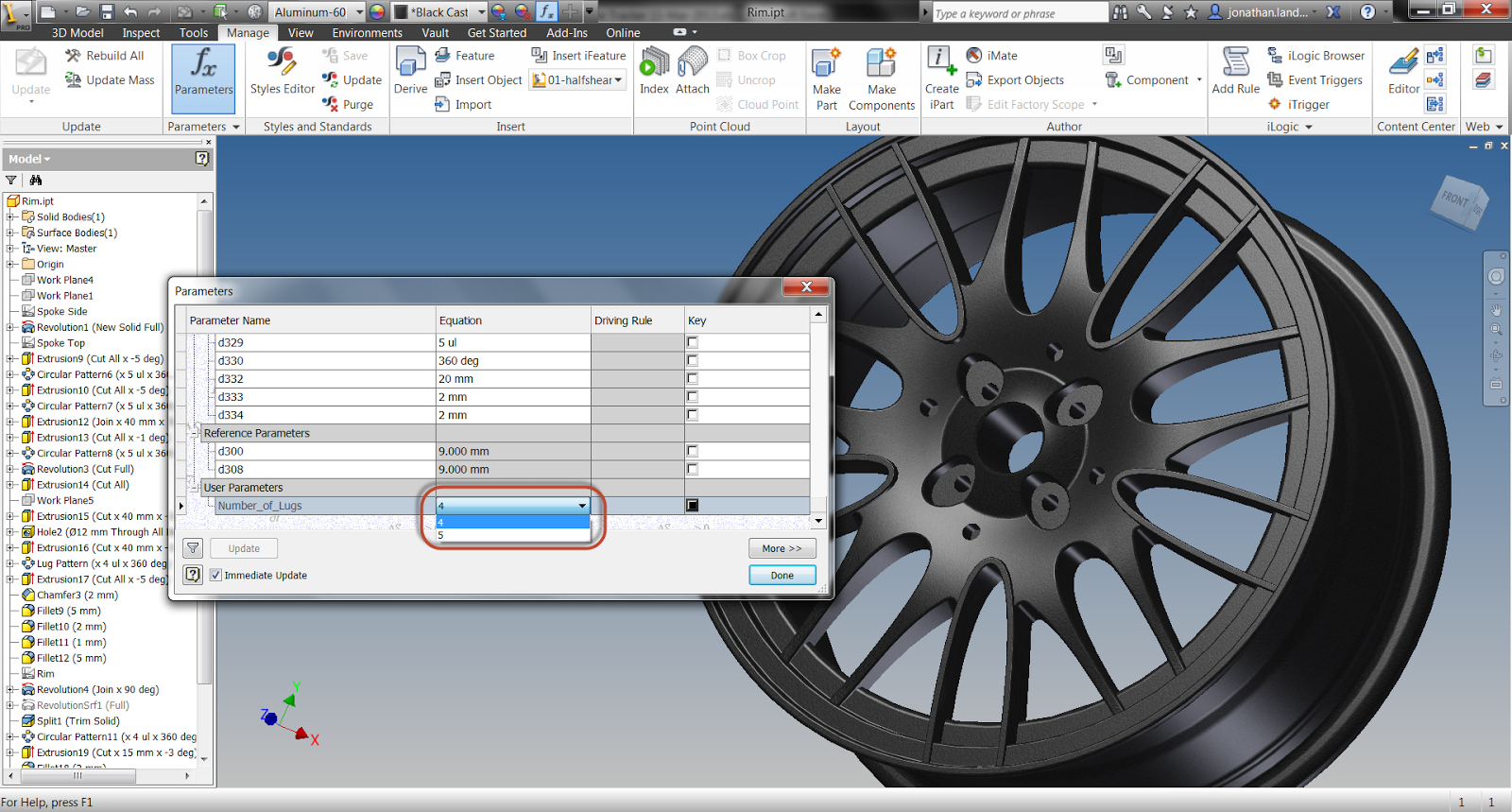
Take a look at this automotive rim (it's just a sample file I'm using). I want to control how many lug holes the rim has.
This is the rim I'll be working with
Even though I've given custom names to the pattern that controls the number of holes, as well as the parameters driving the pattern, I may not know the names off hand.
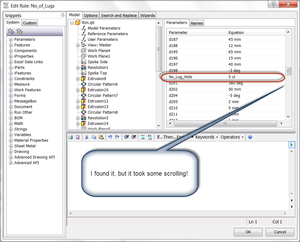
I could pull them from the browser in iLogic, but that could be very time consuming if there's a lot of parameters to sift through, and it can mean a lot of scrolling up and down until the parameter is found.
And this is only one parameter, what if there were more?
The parameter found, after a lot of scrolling up and down, though.
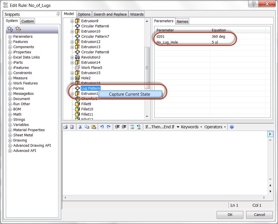
Another way I found that can be extremely helpful is to locate the feature, which even though there's a lot of them here, is easier to locate than a single parameter. Once the feature is selected, right click on it and choose "Capture Current State".
Notice that I renamed the feature too. It makes the feature I'm looking for a little easier to find.
Capturing the current state of the feature
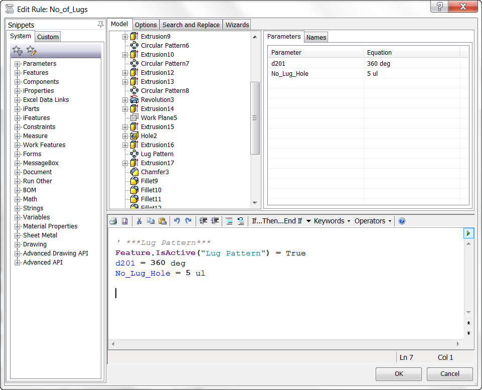
Once the state is captured, iLogic gives me information about the current suppression of the feature, as well as grabbing the parameters associated to the features.
The current state captured
The bonus of this method, is that I can use these values as the basis for creating my rules. I'll start by adding my If/Then/Elseif statements.
Now, I could turn off my pattern completely if I changed the "True" to "False", like the example below: Feature.IsActive("Lug Pattern") = False
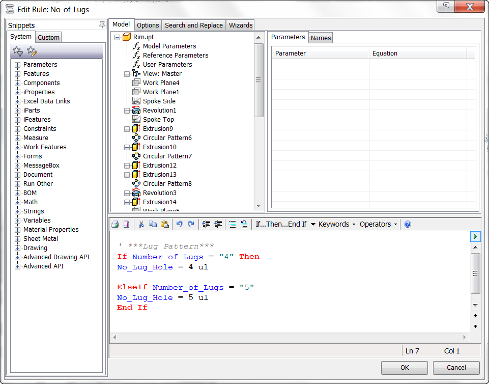
But in this case, I'm only changing the number of Lug Holes, so I'm going to remove the lines that don't pertain to the number of lugs.
The final rule is shown in the image below:
The finished rule.
Now the rule can be checked, and verified.
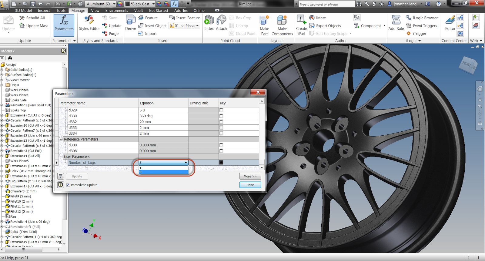
4 lugs, check!
5 lugs, check!
Now this rule can be expanded by getting other states, or by using any combination of iLogic techniques.
For more information on creating an iLogic rule. Check out my post from the archiveshere.
Over many years I've spent staring bleary eyed typing at a computer screen, two of the skills I've gotten pretty good at are typing, and the copy and paste hot keys (those are CTRL+C & CTRL+V if you're not familiar).
But there are times that I've found this doesn't help me. I use the methods I'm used to because they're comfortable.
That was what happened this morning, I was replacing a bunch of variables in iLogic and starting copying and pasting away.
Then it hit me.... Like a palm to the face it hit me!
There are Search and Replace tools in iLogic!
I've been copying and pasting a bunch of entries when I could have just used Search and Replace to get them all in one shot!
The real files I was working on are proprietary, so I can't show it here. So standing in for the proprietary files is a woodworking jig that I'm driving with iLogic.
It's a generic template I created for cutting shapes in boards. It's designed to be copied with Autodesk Vault's copy design tool. Then iLogic is used to change the dimensions of the base and positions of the handles, stop, and clamps to fit the board being cut.
The jig. iLogic drives the dimensions and positions of the components
Here's an example of the code that's driving the jig.
'These parameters drive the Base Dimensions Parameter("Cloudlift Fixture Base Test:1", "Width") = Base_Width Parameter("Cloudlift Fixture Base Test:1", "Length") = Base_Length Parameter("Cloudlift Fixture Base Test:1", "Length") = Base_Thickness
'These parameters drive the Spacing between handles. Parameter("Cloudlift Fixture Base Test:1","Handle_Spacing") = Handle_Spacing
What I really need to do is swap "Cloudlift Fixture Base Test:1"" with "Cloudlift Fixture Base dev:1", to reflect the change I made in a components name in the browser.
The component's new name in the browser
I could copy and paste this with very little trouble. But in the file I was working with (the one I can't show), I had at least fifty entries that needed to be changed.
Now that isn't nearly as easy!
Fortunately, I realized that I could Search and Replace the data before my "Copy & Paste" habit got the best of me.
The dialog box below shows the Search and Replace tab ready to go. I have the text I want to find, and the text I want to replace all setup.
Since I want to change all the appearances of "Cloudlift Fixture Base Test:1" in this rule, I chose the "Replace All in this Rule" option.
Boom! That's it, I'm done!
Search and replace has done it's job!
So what did I learn? Or rather "relearn"?
Don't get too comfortable. Every once in a while I need to take a step back and see if there's a better way to do what I'm doing.
I think if there's anything I'm grateful for this Friday, it's that I had my little epiphany before I started my "Copy and Paste" insanity. It saved me a nice little chunk of time, and a whole lot of headache!
It's been another busy weekend. I was busy catching up with family, so I'm afraid no blog was built today.
However, I have been busy putting a lot of work into KETIV's Autodesk Manufacturing Academy, so as this weeks post, I offer up a preview video for my "Automating Repetitive Designs" session.
This particular video is on the iPart portion of the session
Recall that an iPart is a "table driven part" where a component of shape can be controlled, via parameters. This makes it much easier to create different sizes, colors, and so on, without recreating the part every time. The table helps drive that geometry.
A classic example of an iPart, open up the McMaster Carr catalog, and look at any screw you can find. See that table of values? iPart!
So without further delay, here's a video. Enjoy!
I hope you enjoy, and I hope to see a few of you a the AMA event!
At long last! The final part of my little "iFeatures & Autodesk Inventor" series (at least for now)!
In this final post, I'll discuss taking and iFeature, and driving it via a table.
But first of all, why drive an iFeature with a table? What does a table do for us?
Well the single biggest reason to use a table driven iFeature is to create is to create a consistent series of choices for features that vary in predictable ways.
An Example of an iFeature Table
For example, lets say there's a mounting hole of three consistent variations. It may have two different size holes, but the holes all expand in intervals of a given increment (.125 inches for example).
An example of different holes (yes, I know the biggest one is 'too big'
If a non-table driven iFeature is used, the different diameter holes could be mixed and matched.
The 'standard' iFeature screen
In other words, a "create a combo" situation could arise, and a non-existant hole created.
If a table driven iFeature is used, then the mounting holes can be called out by a specific value, such as an "tool number", and a consistent set of holes can be placed.
Special fields can also be created, so institution specific criteria can be used for selecting an iFeature. For example, in my video, I use Tool Number.
But enough of the describing! Let's switch to the video, and see how these tables can be used!
And on a final note.... Who knows what an iFeature was called before it was named an iFeature? Hint: it's the reason an iFeature has the file extention "*.ide"!
In my last blog post on iFeatures (see that post here), I extracted and placed an iFeature, but that was all we did at that time. I did mention that dimensions could be added to the iFeature, but I stated we'd get back to that.
Well, we're back to it! In this blog (and its video), we'll add dimensions to the iFeature we used in the last blog.
The basic steps for this process are below:
Rename Parameters (okay, this isn't strictly necessary, but it makes the process easier, and I recommend it.
Parameters renamed
HINT! To rename parameters quickly, edit the feature, and type "Parameter_Name = X.XXX" to rename it in the feature. This will rename the parameter directly from the feature it drives.
Renaming the parameter in the feature
Extract the iFeatures you want. Note in the image below, the renamed features automatically are made available to the iFeature.
Extracting the iFeature
Set any ranges or lists you need
Setting a range
Setting a list
Save the iFeature, and you're ready to go!
Saving the feature
Now the feature can be placed, taking advantage of the settings used!
Placing the iFeature. Notice the list being used.
So that will place the iFeature into the parts you intend to use it in, and now you've seen the steps to create this iFeature.
But it would be an Inventor Tales blog without a video. So here it is, a video showing the process!
Have a suggestion on how you might use iFeatures? Throw a comment!
Most of us are familiar with Autodesk Inventor's Parameters. It's where Inventor stores the dimensions that it uses to create it's components.
If you've used parameters before, you might even know that you can rename the parameters to give it more meaningful names than the defaults.
The Parameters used for this part
An additional capability of the parameters is the ability to build equations using Inventor's parameters. Many of us have seen those before too.
Equations in Parameters can help make a design much more intelligent
But what many may not know, is that there are many special fuctions that can be used. For example, the "Ceiling" function can round a number up to the nearest integer, while the "Floor" function will round a value down to the nearest integer.
For example, in the equation below : Maj_Dia_Ht / 0.4375 = 4.571 without an additional function.
Using the Ceiling function to round up to then next integer
But add the "Ceiling" function: Maj_Dia_Ht / 0.4375 in = 5.0 because this function rounds up to the nearest integer.
Why did I use this function? Because I'm calculating the number of holes in the circular pattern, and this number needs to be an integer (you can't have 4.571 holes in a pattern!).
This is just a quick example of what can be done, but there are several functions available/
The Autodesk Inventor iFeature. I've described it as Inventor's version of an AutoCAD Block. When there's a repetitive feature that needs to be placed multiple times with repeatability, this is a place to look.
First, Autodesk Inventor has several iFeatures that ship with it.
Inventor ships with several iFeatures built in
You can find them by clicking on the "Insert iFeature" icon. It's found on the Manage Tab.
Placing iFeatures
But the iFeatures Inventor has may not cover all the iFeatures that might be needed. In that case, new iFeatures can be created and added to the library.
In my humble opinion, I think this is one of Inventor's tools that gets overlooked. While it may be an answer for every solution, there are definitely some places it can make a job go by a lot more easily.
The iFeature has a lot of flexibility, among these are:
The ability to add variable dimensions that can be changed by the user
The ability to limit these dimensions to a list of numbers, or a range of numbers
The ability to create table of variants for different types of placed features
So there is a quite a bit to go over. So I'm going to break this particular blog into parts. So in the first part, I'll just show how we can create an iFeature, and place it onto a part.
A couple of suggestions before the video, I like to create an "iFeature generator". That is, I create a component to build the iFeature.
I do this because if I need to adjust the iFeature, I can return to the generator and make the adjustments I need.
My iFeature Generator for this post
Trust me, I learned this one the hard way. In this case the hard way wanted to make an adjustment to my iFeature, but having to rebuild it because I didn't save it the first time!
So to see how this iFeature was used, take a look at the video!
It's back everyone! KETIV's Autodesk Manufacturing Academy returns to Lake Oswego in Oregon (October 10th), & Cerritos in California (October 25th)! Registration is now open!
I'll be there again, and so will all the techies from the KETIV team!
So if you need a reason for work to send you to Oregon, or Southern California, check out this link!
(nudge nudge) Check out the keynote speakers!
And look below for the "preview movie". If you look quickly, you can see me. It's like Where's Waldo for bald guys!
As you might have noticed, I had a long trip out of the USA to Edmonton, Canada for work. It was a great trip that I enjoyed, but I'm still playing a bit of catchup.
So this week's blog is a bit brief, but does contain a lesson that I've been wanting to share. Once I'm caught up again, I'll be looking to create some more "verbose" blog posts!
One thing I've always liked about Autodesk Inventor's project file is it's ability to set a Workspace that defines a root open and save location for all your Inventor files. It's always helped me keep things a little more organized.
The Workspace helps organize your files
It's a bit of assistance I've always been grateful for.
Although I don't use AutoCAD as much as I did back in the days of R14, I did want a way to direct AutoCAD to do something similar. Open in the directory I'd like.
Fortunately, there is a way to do it. It's a two step process.
First take the AutoCAD shortcut, right click on it, and choose "Properties".
Choosing the shortcut.
The Properties screen for the shortcut appears. Next, choose the "Shortcut" tab and change the "Start in" directory to the desired directory.
Setting the new open location
This tells AutoCAD to start in the folder you define. But there's one more step.
Open up AutoCAD and type "REMEMBERFOLDERS" at the command line. If AutoCAD is set to default, the setting will be "1". Change this to "0".
Now when you start AutoCAD and choose the open or save command, it will open in the folder you set in the shortcut.
Have any suggestions on how you've approached this challenge? Drop a comment below!
I talked about everything but how to rename the labels! By Default, the labels identifying the parameters in form take the form name. But you don't have to keep them! They can be changed!
Example of labels in an existing iLogic form.
Now, changing labels is, for the most part, pretty simple. But I'd hate to imply that it can't be done by leaving it out!
The steps are pretty simple. First, edit the form from the iLogic browser. It's on the "Forms" tab. Just right click on the rule you want to change, and choose "edit"
Choose the form to edit.
The form editor will pop up. Just double click on a label to change it. The description in the form will change.
The process of changing the form "Board Width" has been changed "Board Thickness" is in the process of being changed.
So there it is! Not difficult, but a good to know.
So go ahead and go wild on creating forms!
Have an idea or an interesting use for iLogic! Feel free to drop a comment!
In last week's blog. I created an iLogic rule that changed the length, width, and thickness of a board for the template I use in my woodworking projects. It also turned the tenon joint on and off, as well as setting the dimensions of the tenon.
But, while effective, the rule could be refined to make it more effective. This is especially true when looked at with respect to ease of use.
So in this blog post, we don't make the rule. We make the rule better.
How do we do that? We create a dialog box, or form, that makes the rule easier to interact with. It puts all the critical inputs in one simple, easy to use interface.
The board with the form open.
To create the form, right click in the iLogic Browser, and choose "Add Form"
Adding the new form
Next, drag and drop the desired parameters from left to right to create the form. That's it!
Drag from left to tight to build the form.
Labels of Parameters can also be changed, so you can make them look exactly the way you want them to.
We'll also set up two types of triggers. This will help control when the form is displayed.
The first, is an Event Trigger that will start the form when the template starts.
The second, will fire the form when the iLogic "iTrigger" icon is clicked. This will let us fire the rule, "at will".
In order to create the iTrigger functionality, add a new rule by clicking "Add Rule" from the iLogic Panel on the Manage tab.
The :"Add Rule" icon
Give the rule a name, and type the following code.
'Fires rule when "iTrigger" icon is clicked trigger = iTrigger0 'Shows form named "Board Options" iLogicForm.Show("Board Options")
Where "Board Options" is the name of the form created.
Now this rule will fire when the 'iTrigger" icon is clicked.
Next, we add an "Event Trigger" which fires the rule when the template starts.
Selecting the Event Trigger
Setting the rule to fire when the template starts.
Now of course, this blog post wouldn't be complete without a video! So here it is!
Have more ideas? Leave a comment!
P.S. If you'd like to download the part used for this blog post. It's located on the GrabCAD website here!
One of the side projects I work on semi-regularly is designing furniture in Autodesk Inventor. Mostly, that means taking designs that I find on the web or in books, and increasing the detail to the point of having full piece and assembly drawings.
I quickly learned to create templates containing "board blanks". Templates that contained a board already created, with parameters named "Length", "Width", and "Thickness".
The original template. Just a board with Named Parameters
Instead of redrawing that geometry every time, I would start a template with the geometry already created, and I was off to the races!
But soon, I found that I was using a lot of tenon joints. So I went ahead and created a second template with a tenon joint in it.
The tenon "enabled" template. With it's extra parameters
And I was proud of my ingenuity.
But now the challenge I faced was caused by my poor memory. There were many times I grabbed one of the templates, then part way through realized I should have grabbed the other template!
So I simplified my templates to one template that contained all I needed.
I created a template where I could control the suppression of the tenon using an iLogic Multi-Value List. Now I had something I could toggle on and off at will. With the flip of a switch, a "standard" board, or a "tenon" board.
The combined template. The Multi-Value List shown with it's two options
Over time, here and there, I created a better interface.
Over the years, and releases of Inventor, utilizing spurts of motivation to overcome barren planes of procrastination, I added a dialog box. Now I had something that was easier to interact with then opening parameters
A few months later, I got around to setting the dialog box greet you on file creation, saving the trouble of activating manually.
After completing that task only a few weeks ago, I decided to share this template with the world, so to speak.
This is one of those blog posts that frankly, I procrastinated on a bit. Why? It's a lot to write up.
So to ease the task I'm breaking it up into parts. So, first, let's get something functional.
How to Suppress and Unsuppress the Tenon!
For starters, name your parameters. It makes them easier to work with when creating your code.
Note the bottommost parameter "Joint Type" this is a multi-list that sets what type of joint is used.
Also, note there are a "Shoulder_Length" and an "Overall_Length" parameter. This parameters are toggled depending on whether or not a tenon is placed on the part. Ultimately, this parameter can be exported to the parts list for a cut length.
The Parameter list.
Once those parameters are created. Create an iLogic rule and use the following code to drive the rule.
'If Parameter "Joint_Type" is "Tenon Joint", then unsuppress the feature named "Tenon" If Joint_Type = "Tenon Joint"Then Feature.IsActive("Tenon") = True 'Set Value of Length equal to Parameter "LengthOL"(for eventual parts list export) Length = LengthOL
'IfParameter "Joint_Type" is "Regular Joint", then suppress Feature named "Tenon" ElseIfJoint_Type = "Regular Joint" Then Feature.IsActive("Tenon") = False 'Set Value of Length equal to Parameter "Shoulder_Length"(for eventual parts list export) Length = Shoulder_Length End If
Check out the video below for the fulls steps.
In Conclusion
This portion of the blog only gets to that "functional" part of the rule It works great, but it requires that the parameter screen be opened every time. It may not be elegant, but it is effective.
I ran it like this for quite sometime? Why? It worked, and I never got around to further tweaking.
It's that classic case where I fell victim to "good enough".
In the next post, we'll add a form and make this rule run more efficiently and more user friendly.
A new change in Autodesk Inventor 2013 is how materials and colors are handled. Instead of being a part of the Styles and Standards libraries, like in previous versions of Inventor. Now, they're stored in Appearance Libriares (for colors), and Material Libraries (for materials).
The location of the new libraries can be seen by looking at the project file.
The libraries as shown in the Project File
But what if there are old libraries that have been created over time? We wouldn't want to throw them out and start over right. So there has to be a way to migrate them, right?
Well, of course there is! (or else I wouldn't have anything to blog about).
But how are the libraries migrated?
It's fairly simple, once you know where to look, as I'm so fond of saying,
There are two places to access the Appearance and Materials Libraries.
The first is from the quick access toolbars.
The second, off the Tools Ribbon on the Materials and Appearance Panel.
On the Tools Ribbon
Choosing either icon will bring up the browser for that particular library.
Migrating to both the Material and Appearance Libraries is a matter of clicking on the "gear" icon in the lower left hand selecting "Migrate Inventor Styles".
The dialog for Materials. The Appearance dialog is nearly identical.
The source (the library to be migrated) is selected, followed by the destination library.
However, there are two destinations to send your migrated folder, one is to create a new library, the other, select an existing library.
So what to do?
There's two theories. One is to migrate your old libraries to a newly created one, and remove the old Inventor libraries. This makes sure you have "one truth" for those materials.
The other, is to merge them into the existing library. The important, custom materials will be there.
Which did I choose? Personally I used "Create New Library. For me, it was a little easier to have that "one version" of the truth. I can remove one library later if I don't want it.
Hit okay, and the migration begins.
Soon, the migrated Material Library is complete.
The best part now, migrating the Color Library to the Appearance Library. Why is it so good? It's basically the same steps! If you've done the Material Library, you can do the Appearance Library.
Naturally, it wouldn't be a blog post without a video. So here we go!
Do you have input on how you might have migrated your own libraries! Throw a comment below!


