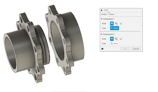
A question that was recently posed to me was; "How would you model safety wire in an assembly?"
 |
Safety wire on a fuel
divider on an
aircraft engine |
At first, I thought I'd write a post trying to summarize the standard, and how I've seen it approached in my travels over the years. But no matter how I tried to "summarize" the standard, it ended up too long, and so dry it put me to sleep. So instead, I'm going to try writing this briefly, and hopefully to the point.
First of all, Safety (aka lock-wire) is small diameter wire of various sizes that is used to prevent fasteners from loosening and ultimately falling out. It should always pull in a direction that tightens the fastener. It's usually twisted with 6-8 twists per inch.
Of course there are more details, but they're covered by standards. In my aviation maintenance travels, that standard is AC43.13-1b, issued by the Federal Aviation Administration (FAA). In my engineering travels, that standard is NASM33540. I'm sure there are other standards.
That's important. The standards tell the installer how to secure the fasteners with safety wire.
So when it comes time to show safety wire on a model or drawing, is it normal to show the twisted wire? Is it modeled exactly as shown in the
image to the right?
Heck no! That takes a lot of time and computer resources, which gets expensive fast. And having a standard to reference, there's little to be gained other than bragging rights for the designer.
Instead, I've seen, and used, on of two alternatives.
The first, is to use a sweep in the model, showing where the wire should go. This takes a little modeling time and dedication, but it will show up on the model, and propagate to the drawing when its created.
 |
Safety wire shown in the model.
I've colored it in red here to make it stand out. |
 |
The modeled sweep representing the safety wire on the drawing.
A leader references the standards in the notes. |
The other, is to use sketch geometry when the drawing is created. It takes a bit of time to sketch in the drawing, but the results do a good job of showing the desired result.
 |
Sketches on the drawing calling out the safety wire
Circles and lines represent the wire's twists. |
Which ever method is used, a note can call out the standard to be complied with. So the wire shown on on the drawing and model show where the wire should go, the note calls out the standard to reference.
If the installer has any doubts, the standard should be readily available for reference. I know in many cases, it's probably even legally required to be available.
The next logical question for a reader may be, "How does this apply to me?" After all, while safe wire isn't uncommon, there are plenty of users who live long, fulfilling lives without ever touching safety wire.
If you get anything out of this post, ponder if there's anything that can be streamlined by adding more or less detail? How detailed does the model of that purchased part need to be? Are you spending extra time showing model details that are covered by a standards that can just be shown by a note with a leader?
Perhaps take a few minutes to think it over. You might find you save hours!
Acknowledgements
McMaster Carr models used:
- Round Head Screws (wire lockable) - P/N 90350A310
- Flat Washer: P/N 92141A011
- 45 degree elbow (37 degree flare to NPT): P/N 50715K637
- 90 degree elbow (37 degree flare to NPT): P/N 50715K413
FAA Reference for Safetying: AC43.13-1b (See page 7-19)
NASM33540: This document is only available for purchase, so I've added a link to the old standard, MS33540. It's very similar to NASM33540, as well as AC43-13-1b


