Find us on Google+ 2022 ~ Inventor Tales

Tuesday, December 20, 2022

Why I chose to use Autodesk Fusion 360

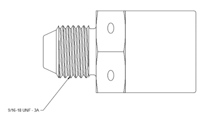
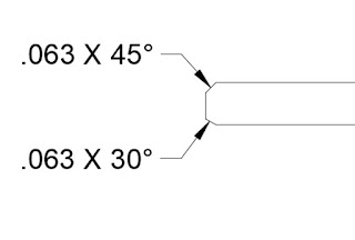
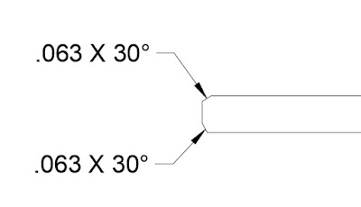
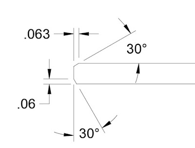
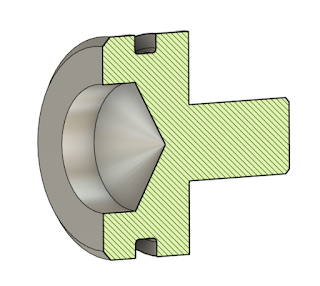
Part of a Hydraulic Valve for 
a P-51 Mustang

Recently, I was asked why I used Autodesk Fusion 360 for my side project of modeling vintage aircraft parts. Why not use Autodesk Inventor? Or Dassault Solidworks?

Sitting down one evening, I decided to take a few moments to share my thoughts. These reasons are purely my own, as one guy cranking out models on evenings and weekends. I'm not an evangelist proclaiming my choice is better than yours. It's just that, my choice. 

Also, I do pay for a Fusion 360 subscription. I chose to take advantage of one of the promotions a few years back. I know this is likely still a hot button issue for some, but in my case, I'm glad I did. I thought it was
important that I mention that, in the interests of full disclosure.

 So, why did I chose Fusion 360? 

Accessibility

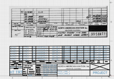
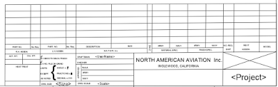
 A hydraulic housing in the
Fusion 360 mobile viewer
 The first reason I chose Fusion 360 it's easy for me to get. Yes. It's as simple as that.

Even if I chose not to subscribe, there's a free version that covers most of what I would choose to do. Sure, there's a cost associated with my subscription. But my cost for a yearly subscription is less than I'd spend on a weekend snowboarding. So for me, it's worth the expense to indulge my hobby.

Sure, there are probably ways I could get an educational copy of Inventor or Solidworks. Some are probably above board, others, more "gray market". 

At least in this case, I don't have to worry about stepping on anyone's
EULA (End User license Agreement). 

Capability

As far as bang for the buck. Fusion 360 does everything I need to do, plus more.

Most of what I do is currently limited to the parts, assemblies, and drawings. I haven't delved into the manufacturing or simulation space. But it's good to know I can do it should the time come!

I have used Fusion 360 to create *stl files for 3D printing and dxf files for a waterjet (see that post here), and overall, I've been happy with the results.

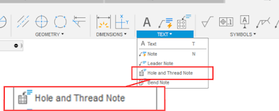
One thing I really like is the way Fusion 360 models threads. More than once I've been able to 3D print a usable thread out of Fusion 360.

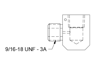
A 3D print created with Fusion 360.
The fitting is threaded into 3D printed threads.

Ease of Administration

I've configured installations for Autodesk Inventor, Autodesk Vault, and to a lesser degree, Solidworks. All these tools are incredibly powerful. But with that, comes a great deal of setup and configuation. Where are the templates placed? How are you configuring your data management system? When you upgrade, what's your migration strategy? What are you using for a server?

For Fusion 360, the server is on the cloud, so there's no data to move when it's time to update hardware. 
When I purchased a new laptop, I installed Fusion 360 on my new computer, logged into my account, and had instant access to all my designs.

There was no need to migrate files or remap file locations. It was already there. In about an hour's time, I was up and running.

In Summary

In conclusion there isn't much, really. 

My big reasons why I chose Fusion 360. It works for me! Does that mean it would work for you on whatever projects you're working on? Maybe, maybe not! That's for you to decide. And whichever way you decided to go, happy 3D modeling!

Monday, August 15, 2022

Using Fusion 360 to Create Parts for a B-17 Restoration

A portion of the original print used to 
create the model.
 For many years, I've created models in Fusion 360. On occasion, I've 3D printed a few of my Fusion 360 models as "desk ornaments". 

But a few weeks ago, I had a fantastic opportunity to create a model that would be used to make a part for the restoration of a B-17 Flying Fortress. 

The part was a "friction washer" for use in the throttle quadrant. And the team needed geometry that could be cut on a water jet.

It started with a reproduction of the original Boeing print. Having the original dimensions made the modeling easy. It was interesting to note that even though standards have changed in the nearly 80 years since that print was created, it's not too different from the prints I work with today. 

The model of the friction washer, created in 
Fusion 360

Next, was to place the view on a drawing. The first goal was to dimension the drawing as a way of verifying all the dimensions were correct. Second, the drawing is what creates the 2D DXF file for the water jet. 

Once the drawing is created, delete any information that isn't required for the waterjet. This includes borders, title blocks, dimensions, centerlines and centermarks, etc. You might even consider creating a second page in the drawing for this purpose. 

Also, make sure to save the drawing before you export. I learned the hard way when I realized that the first file I exported still had all that extra geometry. Save the file before export!

The dxf geometry sent to the waterjet

Once I recovered from my snag. I sent the files off to my colleague for cutting. 

A few days later, we had our part and it fit perfectly, making for a very satisfying little journey. 


And while this little project was well worth a victory lap, there were three minor challenges that are worth mentioning. 

1) Drawing standards have changed over the decades, and while the drawing wasn't hard to interpret, some information wasn't where I'd expect it to be. Modern 3D modelers have spoiled us. We can "slap down" a new view in seconds. For the drafters of old? Adding the simplest view would take minutes. A more complicated one? Hours. 

The number of views was kept to a minimum. A part of single thickness, such as this one, will likely have the thickness dimension called out in a note. 

2) Not only have drawing standards changed, industry standards have changed. That material specification called out in 1943? It's been long superseded by a new standard. It's even possible that the standard that superseded the 1943 standard has, in turn, been superseded itself. 

Be prepared to spend a few minutes Googling the updated standards. Thank goodness for the internet! 

3) Finally, how does one interpret the tolerances called out on the drawing? Symmetric, +/-.005 for example, is easy. Model to the nominal. But what about a tolerance such as +.010/-.000? Do you "split the difference"? Do you aim for nominal? 

In my case, I decided to aim for the dimension as it was called out on the print. I figured that was the target dimension, after all. 

And in my case. It worked! Fusion 360 gave me an excellent dxf file that the waterjet used with no issuee, and the part fit perfectly into its intended position.  

It was a wonderful opportunity to contribute to a restoration. And a wonderful learning opportunity!

Acknowledgements

Print Reproduction via my Aircorps Library Subscription

Models and drawings created in Autodesk Fusion 360

Tuesday, June 07, 2022

My Tool Won't Fit! A Design Lesson From Life.

A typical aircraft brake disk.
There's not much room for a socket!
Hands on experience is often the greatest teacher. 

And, while helping work on a friend's change tires on a light aircraft. 

In looking at the brake disk, bolted to the tire rim, I saw that there was no way one could get a socket, the ideal tool for the job, onto the bolt. 

Fortunately, my friend, having run into this case many times before, had a wrench he'd cut to fit inside the disk. So in the end, it was job that was still very easily accomplished. 

But there lies a lesson for those of who sit behind a desk and design the machines we use every day. 

Just because the fastener fits, doesn't mean the tool will! So when designing, think of ease of maintenance. 

The maintainers, who are sometimes your customers, will thank you for it! 

About the Author:

Jonathan Landeros is a degreed Mechanical Engineer and certified Aircraft Maintenance Techncian. He designs in Autodesk Inventor at work, and Autodesk Fusion 360 for home projects. 

For fun he cycles, snowboards, and turns wrenches on aircraft. 

Friday, June 03, 2022

All PLA Prints the Same, Right? WRONG!

I print a lot of Polylactic Acid (PLA) in the 3D printer at work. I've found it's a great material to work with. It prints easy, and generally gives great results. 

A sample of a different PLA print. 
Usually a great material to work with.
Sorry, the actual print is proprietary.
Almost without exception, I have great results.

At least until all of a sudden I start having problems with it! 

When printing new color, silver from Amazon the PLA started peeling off the bed. 

It didn't matter how much glue I put down on the bed, It would peel up after a few layers. 

So what to do? 

My first step was to try a few troubleshooting steps. 

First, I raised the temperature of the bed from 50 degrees Celsius to 55 degrees Celsius. No luck there. 

Next, a thorough cleaning of the bed with isopropyl alcohol. I definitely had a cleaner bed, but still, the problem persisted.

Finally, I found a trick that solved the problem. Move the nozzle .05mm closer to the bed. Success!

The Z setting adjustment in my slicer.
I moved the nozzle slightly closer to the bed.

What is it about the silver filament? I'm not sure. But during my troubleshooting, I did notice that the gray filament did appear to be laying down a thinner layer. 

My only guess is something with the dye used to color the filament. But that's just a wild guess. 

So what's the takeaway? 

Keep an eye on those layers, and remember that not all filament of the same material prints the same! 

Resources used for this post: 

3D Printer: Fusion3 F400
Slicer Software: Simplify3D

About the Author:

Jonathan Landeros is a degreed Mechanical Engineer and certified Aircraft Maintenance Techncian. He designs in Autodesk Inventor at work, and Autodesk Fusion 360 for home projects. 

For fun he cycles, snowboards, and turns wrenches on aircraft. 


Tuesday, May 10, 2022

So Solidworks Happened at Work Today - A Musing

I've spent just over 20 years working with 3D CAD programs. That experience has been nearly exclusively with the Autodesk manufacturing product line, starting with Mechanical Desktop (shortly after the earth cooled), and followed by Autodesk Inventor. 

We've all seen the ubiquitous, 3D model, floating in space.

A couple of years ago, my company decided to experiment with switching to Siemens NX.

That experiment, unfortunately, failed. Siemens NX, while a good program, wasn't the right program for the needs of my employer. 

A few months ago, my company announced that we would be going to Solidworks. 

Other than dabbling in it a few times, I've never touched Solidworks. This could be an enormous change for me. 

Or not, perhaps? 

CAD Tools - Is it just
a Virtual Toolbox?

I completed an abridged "transfer training", where we were shown where all the buttons were and how Solidworks ticks. After that, we were released upon the world. 

And what did I find? Were my eyes opened to a brand new world? Was Solidworks so much better that I wondered what I was missing? 

Did I wail and gnash my teeth because Inventor was far better and I was being forced to use this inferior product?

No. I left that training and thought, "Wow! They're really similar." 

Sure, Solidworks has an Extrude and and Extrude Cut button, while Inventor has the same options combined within one Extrude command. But they both add and remove material in the end. 

There's functions where I think Inventor has it down better, and others where I have to give it to Solidworks. 

In the end, I see it as an opportunity to learn a new skill, enrichen myself, and be more marketable in a competitive world. I think that's going to take me further in the long run. 

So I suppose the point of my writing this is to muse about how CAD programs are tools. They're not the endgame, there the means to create our designs, drawings, and help us build our products. 

And there's nothing wrong with learning a new set of tools. It can only make me a more marketable designer. 

One Final Note

If you're using Fusion 360, you can change your Pan, Zoom, Orbit shortcuts to reflect Inventor or Solidworks, among other programs? 

I've switched mine to Solidworks, it may not be the same as having Solidworks at home, but it does makes it easier when I switch from one to the other at work! 

The Pan, Zoom, and Orbit options in Fusion 360


Saturday, March 12, 2022

The Chamfer Note. Does It Say What You Mean?

Many CAD tools contain a chamfer note that I would describe as a leader style. 

You've probably seen it, probably used it even. 

It utilizes a leader to point at the chamfer, and contains both the chamfer distance, and angle in one simple note.

The advantage of this style is it's compact, easy to read, and especially easy to place when the chamfer is packed into a crowd with other nearby dimensions. 

But this dimensioning style as a subtle disadvantage. This style of dimension doesn't identify the direction of the chamfer. So if the chamfer angle is something other than 45 degrees, the angle direction is open to interpretation. 

Even though the chamfers are different, the callout is is the same. 
It's also correct in both cases.

That literally means that a chamfer in either dimension meets the print. That can cause confusion, and possibly "heated debates" when a parts acceptance or rejection hangs in the balance. 

The other option is to call out the chamfer distance and angle as separate, distinct dimensions.  This identifies the direction of the chamfer much more clearly.  


Of course everything is a trade off, and this method does take a little more room on the page than the leader style. Even on the image above, you can see that the page is a bit more cluttered, and someitmes a detail view is required to ensure all dimensions can be clearly seen. 

In the end, I find I use both. The leader style is used for 45 degree chamfers, since there isn't really an angle direction to speak of. However, when the chamfer is an angle other than 45 degrees, it's time to employ the explicit style, and make sure the direction is clearly shown. 

Ultimately, it's up to you which chamfer style you use. Perhaps you have the advantage of tribal knowledge to correctly identify these features. Or you have other means to make sure the chamfer is cut the correct way. 

If anything, this is a good practice hailing from the time when "back to the drawing board" was a much more literal statement! 

About the Author:

Jonathan Landeros is a degreed Mechanical Engineer and certified Aircraft Maintenance Techncian. He designs in Autodesk Inventor at work, and Autodesk Fusion 360 for home projects. 

For fun he cycles, snowboards, and turns wrenches on aircraft. 


Thursday, February 03, 2022

New in Fusion 360 - Improved Thread Notes

 Sometimes it's the little things that make a guy happy. 

A thread note placed
on an external thread

In this case, it's the improved thread annotation tool in the January/February Fusion 360 update. 

In short, Fusion 360 can now create an annotation for a thread note placed with the thread tool, not just the hole tool as was the case in previous updates 

That opens up the field to place thread notes onto external features. It's a capability I've personally been hoping would get added for some time. 

Admittedly, applications like Inventor have been doing this for what seems like eons, so it's hardly a "ground-breaking" feature. 

But it sure is a nice feature to have! 

All you have to do is place the note using the "Hole and Thread Note" command, and you're off and annotating. 

Locating the "Hole and Thread Note" tool

One little cool thing I noticed in my evening of poking about. 

The tool works with threads created using the "modeled' setting too! 

A modeled thread with a thread note.

I've been waiting for this enhancement for a while! I'm glad it's finally here! 


About the Author:

Jonathan Landeros is a degreed Mechanical Engineer and certified Aircraft Maintenance Techncian. He designs in Autodesk Inventor at work, and Autodesk Fusion 360 for home projects. 

For fun he cycles, snowboards, and turns wrenches on aircraft. 


Saturday, January 08, 2022

A Milestone Creating a Fusion 360 Title Block!

I have completed the task I challenged myself with in my previous post. I finished up my reproduction of a 1940s era North American Aviation title block in Autodesk Fusion 360!


The original, and Fusion 360 Title block together


It was a little tedious at times, it's a lot of repetitive sketching geometry and inserting text and properties. 

But it's completed, and ready for use. I'm sure I'll find a few more things to adjust as I test it out. 

Ultimately, I was able to recreate nearly every feature of the title block. It's not an exact match. I couldn't find a solid fill to block out the box above the part number for example. But it is close, and it will serve it's purpose just fine. 

As more features get added to Fusion 360, I'll update the title block accordingly. 

The North American Aviation tile block finished

So now, it's time to start creating drawings! From there, I'll learn more lessons and make more adjustments!

Credits:

Title Block Sourced from my Aircorps Library subscription.

About the Author:

Jonathan Landeros is a degreed Mechanical Engineer and certified Aircraft Maintenance Techncian. He designs in Autodesk Inventor, Siemens NX, at work, and Autodesk Fusion 360 for home projects. 

For fun he cycles, snowboards, and turns wrenches on aircraft. 


Sunday, January 02, 2022

A Trick - Creating Fusion 360 Title Blocks from an Image

 Happy 2022! Here's to hoping for a prosperous loop around the sun. 

One of my latest endeavors has been recreating 1940s aviation prints as 3D models in Fusion 360. The drawings are available via my Aircorps Library subscription, and they're a great look into how parts and assemblies were documented nearly 100 years ago. 

A piston for an actuator on a North American P-51 Mustang.
Model created in Autodesk Fusion 360

The models are the fun part for sure, but I also decided to recreate the drawings themselves too. 

The first part of recreating the drawing, is to recreate the title block of course. 

The title block image, ready for import into Fusion 360
\

It's still a work in progress, but I thought I'd spare a moment to document my progress.

It almost goes without saying, the process can be tedious. Since the original drawings are hand drawn, they have to be recreated from scratch. 

The thought of trying to "eyeball" the title block wasn't very appealing, but finally an idea dawned on me that made the process much less challenging. 

I imported an image of the title block, scaled it to a suitable size, and laid out the geometry on top of the image.

The title block in Fusion 360. The lines sketched in Fusion 360 are highlighted.

Overall, I felt pretty well. But there was one thing I did have to overcome

There's no image opacity setting like there are in other parts of Fusion 360. But I was able to see where my sketched lines were by highlighting them. I also extended the lines beyond the edges of the image. I can always trim them later. 

Finally, I'd also use the good old, "Delete, Inspect, Undo" trick by deleting the image, inspecting, and undoing the delete.

Overall, its working pretty well. I've found the process is much faster, accurate, and less frustrating than trying to scale by using the title block in a separate window. 

As I said earlier, it's a work in progress.  I'll share my final product when I'm done. Give me time, it might be a while! This is an "evening here and there" project! 

One Final Note

The team at Aircorps Library have done a spectacular job collecting, scanning, and sharing these vintage documents. Out of respect for their work, I won't be sharing any documents or models. Please, don't ask me to do so.

If you are really interested in their documentation, feel free to check out their site and investigate a subscription yourself! 

About the Author:

Jonathan Landeros is a degreed Mechanical Engineer and certified Aircraft Maintenance Techncian. He designs in Autodesk Inventor, Siemens NX, at work, and Autodesk Fusion 360 for home projects. 

For fun he cycles, snowboards, and turns wrenches on aircraft.