Autodesk University 2012 has been just great. I've learned a ton of new things, and met a ton of great people. It's been a pleasure to meet so many people that I've only known online until this week!
A sea of AU attendees. Dedicated, interested, at energetic AU attendees!
It's also meant running around fueled on adrenaline and coffee, so it's been hard to have a few minutes to write up a blog post.
But I can at least leave everyone with a couple of images and videos, and show what I great event it's been!
The Rally Fighter. Just a way cool car developed by a small company in only months!
Technology at its finest. The Embrace Nest helping save a premature baby's life
A description of the Embrace Nest
And also video on the ShopBot CNC Router, which has models that cost less than 10,000 USD! Sure, it's not cheap, but for technology that was tens of thousands of dollars before, this is pretty amazing!
Also, MakerBot has a 3D printer that can be obtained for 2200 USD! And while for the "Average Joe" that's not small change. This technology at one time was hundreds of thousands of dollars. It's amazing how technology like this is becoming more mainstream, and more obtainable.
Today I'm reporting in from Autodesk University 2012! I haven't been here since 2008, and now that I'm here. Just feeling the energy of the place has made me realize how much I've missed it!
Welcome to AU2012
It's going to be a great time of learning, networking, more learning, and seeing some very cool technology.
An amazing wine rack in Mandalay Bay. That's technology, right!
'I'm sure I'm going to be going like crazy as I try to assimilate all the cool things that I'm seeing, but I'm hoping to share it all here as the days tick by
Heck of a view from my room!
There's not much to report yet, but that's only because things haven't gotten started. But soon, I'll be in the thick of it.
With this description of how I built the four sided gaming die, my series is nearly coming to a close.
The completed four sided die. The yellow "spines" are the work axes used for the circular number to complete the numbers
This is a recreation of a die I created for a friend who was making a website for Dice House Games in Fullerton. Ironically, they're right next door to the KETIV office!
I had to recreate the die because I lost the model in between laptops, but I think this is a better design that the original. So here it is for everyone!
This particular die was pretty simple. The construction was nearly the same as creating half of the eight sided die. Although there were some variations with the numbers and basic construction.
The first step, was to create a triangle on an origin work plane. This becomes one base of the die.
Starting the 4 sided die
\Next came a challenge. I needed to create a point on the midpoint bisector of the triangle. For this, I had to reach back into the high school geometry I swore I'd never use! In truth, I only needed two lines, but the third helped me make sure that everything was right!
Bisecting the triangle
With this construction complete, I could now place a point on the intersection of the lines, and a line through that point, and perpendicular to the plane of the triangle.
I next made sure to make the hypotenuse of the imaginary triangle made by the line the same
length as the side of the first triangle I sketched (a screen capture
probably makes more sense here).
Creating the line perpendicular to the first sketch.
Now I lofted from the triangle, to the point I created. That's it, now I have a four sided die!
Creating the loft that creates the die.
And next I break the sharp edges with a fillet.
Breaking the sharp edges
And now the numbers! In this case, the numbers were actually a little easier. Instead of creating each number one at a time, the shape and design of the four sided die allowed me to use a work axis and utilize the "circular pattern" tool to finish out each number. This way, I only had to position each number once. The circular pattern took care of the rest!
Using a circular pattern makes it easy to create the numbers!
And viola! The four sided die!
And I'm done!
Of course it wouldn't be finished without a rendering in Autodesk Showcase.
An now a little rendering!
If you'd like, you can download the file from the pages below!
In this video Marion has created, she provides us with some great tips on using accent lighting in Autodesk Showcase.
I learned quite a few tricks by watching what she's done, and I'll definitely review this video later, as well as keep a close eye on her channel!.
Here's the video below on this tip!
And for those out there that are heading to Autodesk University next week, I'll see you there! I'm getting all my things in order to arrive Monday. If you're going, I'll see you there!
When I training Autodesk Inventor, I always take a little bit of extra time on the break out view in drawings. It's a great way of showing details for internal parts inside an assembly, and not difficult to create in Inventor.
A break out view shown created
But when creating a break out view, it's got one place that usually snags everyone as the first few times they use it. I know it got me when I first started it.
That step is, associating the sketch to the view. If the sketch isn't associated to the view, the break out view won't work, and the breakout command will error out.
This is the error seen when the sketch isn't associated
So how is the sketch associated? What is it that's so special?
I'll talk about all the steps, and specify that special step to create the sketch association.
1. Click on the view that the breakout view will be placed on. The border will highlight, indicating it's selection. This is the critical step that will create the associated sketch!
Make sure to select the view before creating the sketch!
2. Now, click the "Create Sketch" icon. The sketch is created, and it's axes will center on the view. It's this centering of the axes that tells us the sketch has associated to the view.
Creating the sketch
The centered axes tell us it's working
3. Now sketch a closed figure around the area to break out. It can be any shape, it just has to be closed. Here I use a spline. Finish the sketch when done.
Sketch the break out view boundary
4. Now click on the "Break Out" icon. Select the sketch with the view.
The break out icon
5. Define the options for the break out. One helpful tip is to point out that projected views can be used to help with the definition, not just the view that will host the breakout. In the image below, I've used a projected view to define the break out depth.
Setting the options for break out
6. Choose okay and the breakout view is created.
The break out view created
I could say "That's All Folks", but instead, here's a couple of other tips that I find helpful.
There will be times that not every component in the break out view is supposed to be sectioned, as step 6 shows above. Here's how to change that.
The first is to locate the part in the feature browser, right click on it, locate "Section Participation", and changed it's setting to "None".
Setting the section options from the browser
The other is to hold down the "Shift" key with nothing selected, and right click. Choose "Part Priority" from the menu.
Setting part priority
Now select the part on screen, right click, and the same options for "Section Participation" are available.
Setting the section participation from the right click menu
Which ever means you prefer, the sectioning for selected components can be turned off, if desired.
A completed section, with specific parts unsectioned
On a last tip, I've shown what happens when the selections are correct, but how can you tell when the view isn't associated, so a mistake can be quickly corrected before the error on view creation appears?
There are two quick ways to tell.
1. If the sketch is created, but the axes aren't centered on the view, the sketch isn't associated.
2. If the "Project Geometry" icon is grayed out, then the sketch isn't associated. This is because Inventor doesn't see any geometry to project. If the sketch is associated it will.
Two ways to tell if the sketch isn't associated
In conclusion, I hope this helps a few of you out in the "Verse" with break out view. It's a great tool, and can be a great way to add informative detail on a drawing.
This seems to have become a Friday series. The last few weeks I've placed a model of a gaming die on my blog, and talked about the process I went through making each one.
Here's the completed die as an embedded 3D dwf file. Click and drag to give it a spin!
This one is a pretty simple model to create, at least when compared to the others!
First, I sketched a square on an origin workplane. In my case, I chose the XZ workplane.
The first step that starts it all
Next, I bisected the square with a line, on a plane perpendicular to the sketch I first used. It's worth noting that I later on realized that I only needed half the line, but I left the die as I started it.
Added the perpendicular line. I later realized I didn't need the whole line
Now, it's time to create a loft from the square, to one of the line's endpoints.
Creating half of the die
With half the die completed, I used the Mirror command to create the other half of the die.
Using the Mirror command to create the other half of the die
That takes care of the heavy lifting! Now, I just add a fillet to break the sharp edges. Notice that I used the "All Round" option to select all the external edges at once.
Breaking the sharp edge
Finally, the long tedious task of adding the number. This hasn't changed, its just a matter of creating a sketch with the number, and extruding it a shallow distance. At least there are fewer now!
The process of adding the numbers
And because I can, here's the quick rendering in Autodesk Showcase.
And a rendering to make it look cool!
P.S. If you're wondering why I didn't loft from the line's endpoint, to the square, to the other endpoint, here's what happened when I tried.
Needless to say, this wouldn't have made a very good die. So I changed my approach, and used the Mirror command instead. But now you know why I created the line the way I did. It's a vestige of an aborted work process!
As of May 2013, The Augmented Reality Plugin for Autodesk Showcase has been retired. I liked this plugin, and the post does state that it may be back at a later date.
My fingers are crossed!
Shame on me for not updating this sooner, but things sometimes go into the archives, and collect dust.
******************
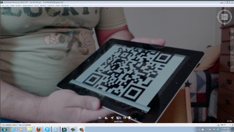
1) Instead of printing out the markers, try using a mobile device, such as an iPad or Android to host the marker
Holding the iPad with the QR code marker
2) Instead of the markers provided with the plugin, use an image created from the scene. This will make it look like the 3D model is "growing" from the 2D image.
I didn't have as much luck with this step. I was able to create a marker using the exported 2D image, but when I tried to use it as a marker, the model seemed to have a difficult time picking up the marker, it was jumpy and inconsistent.
But I did get the effect I wanted. It took some trial and error, a few more ideas, and a slightly different approach.
And here are those steps!
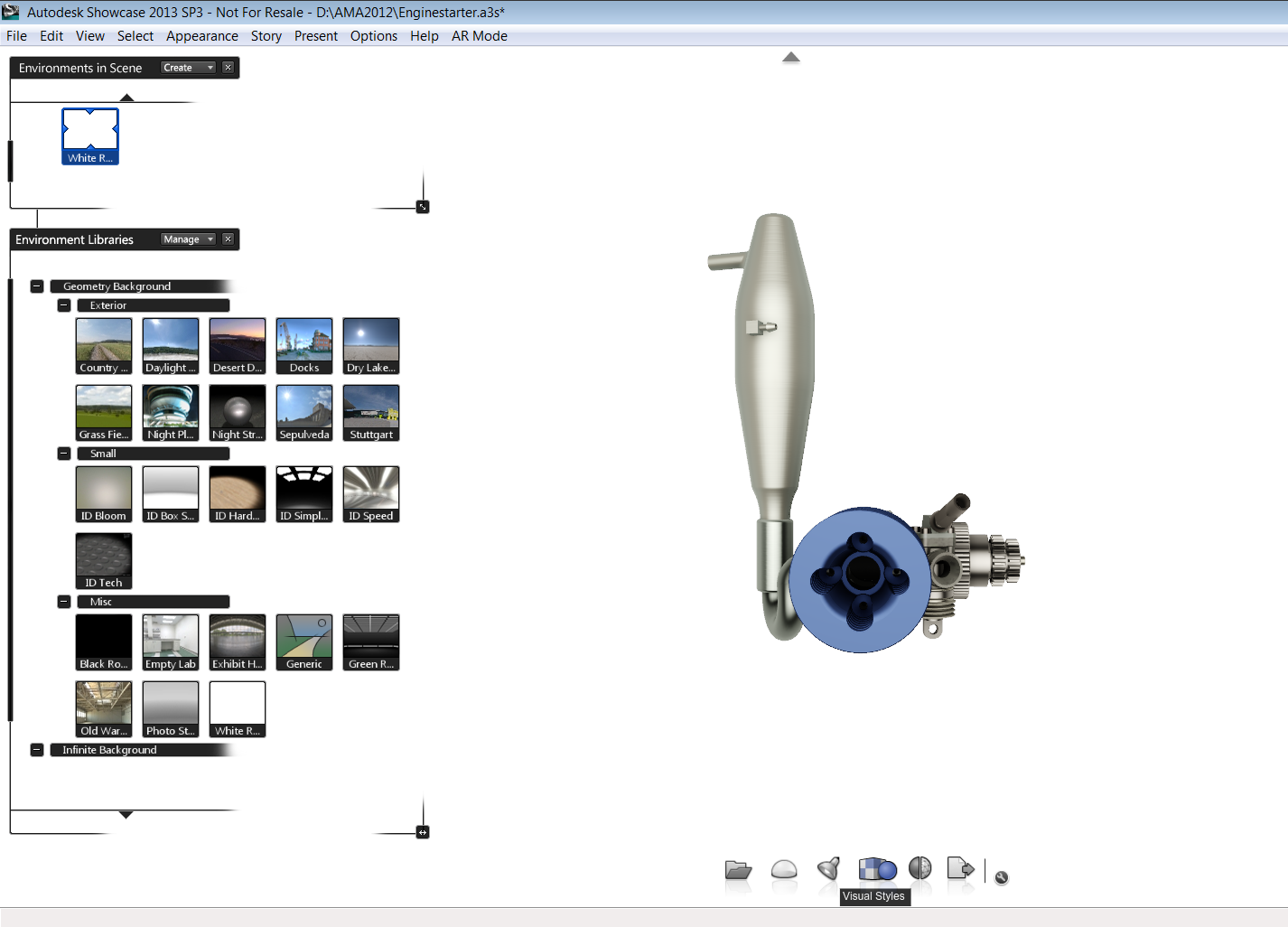
The first step was to create an image of the scene I wanted to use, and set up the angle I wanted using the "White Room" environment. I also turned off the shadows for this environment.
Using the "White Room" environment.
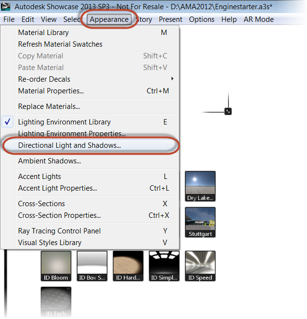
I also went to the Appearance>Directional Light and Shadows.
Locating the pulldown
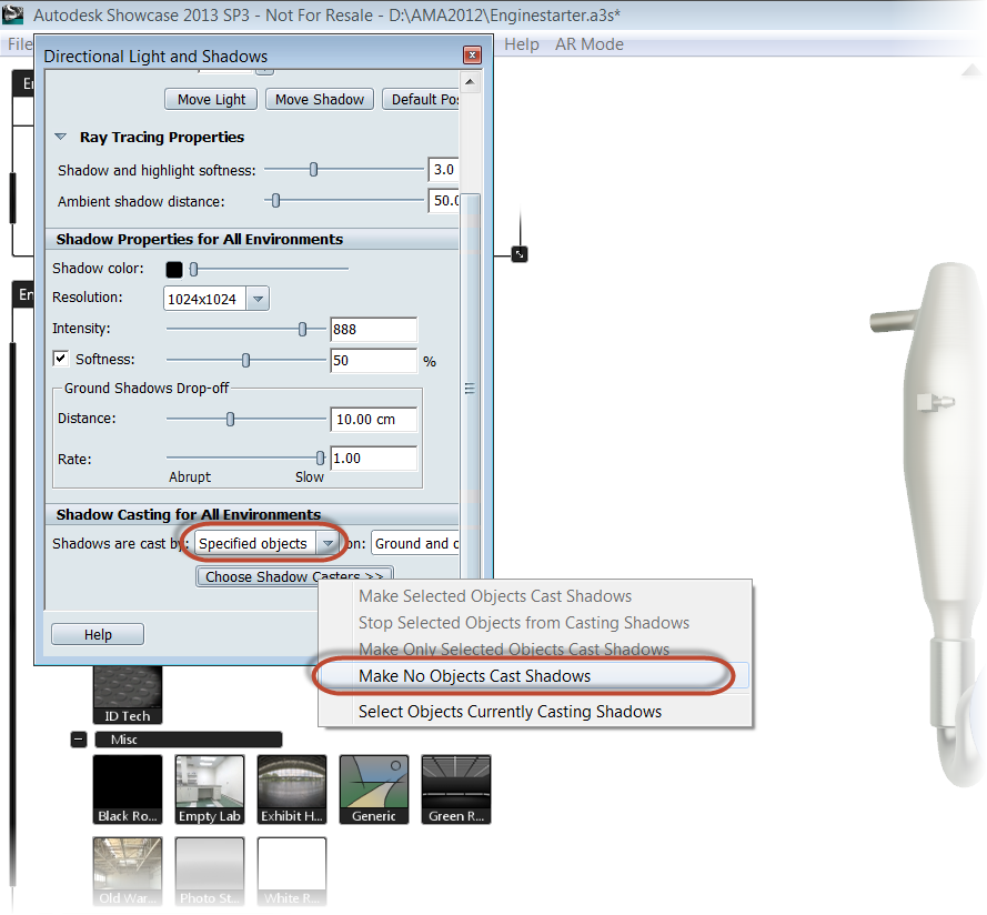
I then set the "Shadow Casting for All Objects" to "Specified Objects, and changed it's setting to "Make no Objects Cast Shadows".
Turning off Shadows
Next, I published the image to a *.jpg
Publishing the image
I then created a decal, using the jpg I just exported.
Creating the decal, with the critical settings shown
I then placed that decal on a "floor" I had created in Inventor, then imported and positioned in Showcase.
The decal placed, and being positioned
Once this is done, I setup the Augmented Reality and I was ready to go! And here's the video that goes with it!
P.S. If you're going to Autodesk University in Las Vegas this year, look for me! I'm going to be there myself!
P.S. the view below is an embedded 3D DWF that can be panned, zoomed, & rotated!
This one ended up being the most challenging so far, at least until I got the construction method down. Once I had that figured out, it wasn't hard, just time consuming.
So here are the steps I used to build it!
The first thing I did was locate directions on how to build the shape that eventually becomes the die. It's called a dodecahedron, and like the 20 sided die, I found it's construction on Wikipedia. It was composed of using a rectangle, and points placed at certain coordinates in space. The Wikipedia article gave me these coordinates.
The construction for the die
I took this information, and using a rectangle extruded as a surface, and three rectangles, created the required points. The points are the verticies of each figure.
The skeleton that starts it all
Next, comes the process of creating the faces. I used a workplane between three point on the skeleton. Created a 2D sketch, and started projecting geometry and sketching the boundaries of the face. This takes some time and patience.
Getting started with the construction
Further along in the construction. I turned off the workplane visibility to try to make the image a little more clear.
Once the skeleton was finished, I went through and created boundary patches that filled in each face of the die.
Now surfaces close up the shape
With the surfaces created, now I used the "Stitch" command to seal surfaces up, converting them to a solid.
The converted solid
My next step was to add a fillet to break all the edges.
The fillet added to the die.
Finally, the long, long process of adding 12 sets of numbers to the die. It's not difficult, but like most things creating these dies, it takes time, it's an exercise in more time, and more patience.
The sketches in the process of getting created.
Finish the text and I'm done
Finally, a drop into Showcase to give it a little flair!
So there it is, one more die out of the way. I still plan on doing the rest, 8 sided, 4 sided, and 6 sided (which is easy).
On a final note, if you want to download the models. You find them on GrabCAD and Autodesk 360.