This blog post is going in a slightly different direction than what I've historically done.
My work these days is less "CAD-Centric". I'm not teaching and supporting CAD anymore. I now use CAD as a tool to create and update designs. I/m back in the trenches, if you will.
Instead, this post is a journal on a lesson I've learned "on the job". The kind that I record in a tattered old composition book I've had for years.
I present my "Lesson from the Red Composition Book".
 |
| My battered red composition notebook. Next to an after work beer. Enjoyed responsibly of course! |
It started as an interesting challenge to modify ab design.
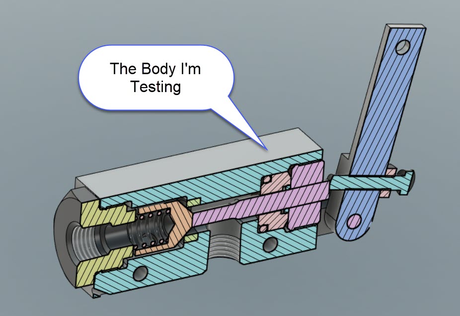
DISCLAIMER! I can't share the actual design, due to proprietary issues, so the images I'm showing are a facsimile.
 |
| My sample wear plate in its base plate |
The design was already created, and needed a hardened wear plate added to increase the product's durability.
So far? So good? Right?
But there was a challenge. The plate the wear plate wasn't very thick.

That meant the wear plate would be even thinner.

In  turn, that meant the countersunk screws required to hold the wear plate in place wouldn't have a lot of room for the countersinks required to hold the wearplate in place.

They have an 82 degree head, and in this case, it mattered.

A countersunk screw with an 82 degree head.
There isn't much wall there!
The solution? Take a cue from the aviation world, where 100 degree countersinks are more common. For those looking for the screw, you can look up MS24693.
Thank goodness for the aviation part of my experience!
 |
| A countersunk screw with a 100 degree head. Now there's room to work with! |
With a little CAD work, the models and drawings were updated, and off to review.
To conclude, I suppose there are two lessons to be learned here.
First, don't forget to use all your experience to help solve a problem.
And second? Those 100 degree fasteners can really come in handy when you're dealing with thin walls!
Finally, I think I'll add some more lessons from that battered and tattered red composition book. If only to move them from a disintegrating book to a more robust solution.
Hopefully, they help a few other designers along the way.
Acknowledgements:
Sample models built in Autodesk Fusion
Screw Models Downloaded from McMaster-Carr