Find us on Google+ July 2009 ~ Inventor Tales

Friday, July 31, 2009

Hotfix for Autodesk Design Review and PDF Printing


Home computers are being called upon to perform many new functions, including the consumption of homework formerly eaten by the dog.
Doug Larson

Something I guess you might consider from the "Public Service Announcement' desk.

The other day at KETIV, I was asked about an issue where pdfs printed from DWF files in Autodesk Design Review were taking a much longer to print out than in previous versions.


A quick check of the Autodesk website showed that there's a hotfix for this,so it should be an easy fix.

So if you're seeing this issue out of Design Review 2010, just grab the hotfix HERE, and you should be on your way with faster PDF creation!

Have a great weekend everyone! I'm off to my volunteer gig at the Planes of Fame again, so that alone is going to make it a great weekend!

Jonathan

Tuesday, July 28, 2009

Beauty and the Eye of the Beholder - Textures in Autodesk Showcase


Everything has beauty, but not everyone sees it. ~Confucius


I've blogged on bump mapping in Autodesk Showcase before, but with so many things in Showcase, it seems like it's as much art as science.

Of course you can add materials in Showcase, and in previous blogs (click here) I talked about how you can use bump maps to add 'character' to a material.

But at times, when trying to use bump maps, you end up with a ray traced image that seems to be grainy. Look at the clamp below. Everything seems fine, but the clamp definitely has that 'grainy' appearance.


(click to Enlarge)

You're first instinct might be to crank up the resolution, but it doesn't seem to help. Trust me on this: I've tried it. It eats up processor time, and doesn't improve the quality of the image. It also tends degrade the temperament of the operator.

But there is hope for both the image quality, and operator mood!

As with many things with Showcase, this is somewhat subjective, but one things that operator instinct seems to be to make a bump map far deeper than it needs to be.

Even looking at the bump map that I've used (unaltered from the Showcase material library) has a bump depth of 1.0, which is pretty high. You might think it's the highest possible setting, but I've found that typing in a higher number will let you go higher than 1.0.


(click to enlarge)

The solution that I've found? I drop the depth of the bump map down. And when I say down, I start cranking it WAY down. I usually cut it in half, then half again, and repeat that process until I get to the result I like. So if I start a 1.0, I go down to 0.5, then 0.25, etc.

You should be able to find a value that works. In this case, I found that I got to a value of .125before I was happy with the result.

So you can see how just changing that bump map can change the look of the file. Other settings you can user are the angle of a bump map, as well as the scale. (For example, I also changed the angle and scale of the wood grain to make it more appealing).

(click to enlarge)

While subtle, each of these settings play their part in
helping create a rendering that is really eye catching.

As another example, here's a box with only the bump depth changed. In the first image, the bump depth is at 1.0. I refer to this as 'having a brushed finish applied with a chainsaw). Feel free to use that, but I want the credit! :-)

(click to enlarge)

Now, setting it to .032 (with a few iterations in between), we get to something that's a little bit more subtle, and far more compelling, I think.


(click to enlarge)

Have fun trying different settings, and try something a little bit 'crazy'. You may find that it makes the rendering really 'pop'.

In which case, you get to make the transition from 'crazy' to 'visionary'.

As for the jig? Here's teh full image, I cleaned up a few things, and gave it a tilt. Here it is in all it's ray traced glory.

(click to enlarge)

Enjoy, and have a little fun trying different variations of these settings. I find it's when I'm having fun, I do my best work in Showcase.

Friday, July 24, 2009

Stranger in a Strange User Group.


Not until we are lost do we begin to understand ourselves.

Henry David Thoreau

Last night, myself, as an Inventor User, found myself in what can definitely be considered foreign territory.

I found myself in an Autodesk Revit users group.

No, I didn't get lost on the way home.

I was looking into the new AEC Exchange functionality in Inventor R2010, and how it talks to Revit.

But I'm a manufacturing guy. I change my own oil, think unburned fuel may as well be perfume, and believe that the sound of a P-51 Mustang running at full power is the the sound of angels singing.

Those who've heard, know.
(click to enlarge)

Architecture? Well, that's not my gig, let the pros take care of that, right?

But there's an undeniable fact that users of Inventor have to create files for buildings (after all, that air conditioning system is being manufactured somewhere, isn't it?)

I'm fortunate that Jay Zallan, Autodesk Revit User Extraordinaire and BIM Scholar invited me to the South Coast Revit User Group (SCRUG) to visit.

I was really impressed by the energy of the meeting, everybody was energetic, passionate, and constructive about how to best use Revit.

Door Families. The topic of the night.
(click to enlarge)

They were also very welcoming to a somewhat curious and puzzled Inventor user who had passed through the looking glass into an architectural world.

Moreover, they were more than willing to offer their help and guidance as I learned more about the things that are vital to the project they're work with on a daily basis.


Look! I library of doors! Library... We do speak the same language!
(click to enlarge)

I have to say that I left their group more excited about the possibilities than I had when I was when I arrived.

I'm really looking forward to having a chance to work with them in the future!

Look to upcoming blogs on our progress on AEC Exchange!

Happy Weekend everyone! It's about that time here in California!

For more information on AEC Exchange, here's the Autodesk video that discusses it. Note the epic 'Announcer Man' voice. :-)


Wednesday, July 22, 2009

Content: Why Reinvent the Wheel when You Can Download it?


One of the Internet's strengths is its ability to help consumers find the right needle in a digital haystack of data. ~Jared Sandberg

Not that long ago, I was talking with a friend at PARTsolutions about finding content on the internet. While much can be done with various search engines, he reminded me that sometimes more quaint forms of communication, such as putting your Blue Tooth headset in your ear and making a cell phone call in the car on the drive home, are still valuable ways of communication.

It was during this conversation that he reminded me that Autodesk has its Manufacturing Supplier Content website available.

Granted, I had heard this before, but somewhere it had fallen behind the file cabinet of my mind and gotten lost.

So I went to the website HERE and took a look.

I did have to create a login, but I went ahead and created one, and took a look.

Enter the beam of light and the choir voices singing...

The image shown in the screen capture greeted my eyes.


(click to enlarge)

So much content.... It was just so.... pretty... and contenty....

Once I shook off the initial shock. I decided to check out some content. After one aborted attempt, I double checked some settings. This will setup the default format to download.


(click to enlarge)

With those preferences saved, I went out and chose a component to download. I noticed DeStaco clamps was one of my choices, and I used a grip of DeStaco clamps when I was in industry. So that's who I went with.

(click to enlarge)

I clicked through a couple of sections, and got to the good ol' toggle clamps that were an ever present part of some of the fixtures I built. I even found a part number that I recall using, complete with preview.


(click to enlarge)

Once I found the part, I clicked on the Part Download button (which looks like a little Socket Head Cap Screw) and the site built the parts for me to download. The down loadable content will appear in the lower right hand side of the screen, and you can click on the 'disk' icon to download it.

(click to enlarge)

Once you click on the download icon, you'll be asked to save a zip file to your drive. Extracting the zip and opening the file in Inventor, here's my result.

In a few moments, I have the clamp as an assembly that I can use in a design. It's accurate, and up to date, straight from the source.


(click to enlarge)

Granted, all the parts are grounded, but I can add the constraints pretty quickly. I even changed the colors of the parts to look a little more realistic.


(click to enlarge)

If you really want to go wild, you can even add positional representations and create the open and close positions for the clamp.


(click to enlarge)

The key, I think, is the fact that the geometry (which is the heavy lifting) is already there.

However far you decide to take this. You can (and probably ought to) save it in some sort of library, be it a location on the server, or checking it into Autodesk Vault.

Now your off and running on other components of your design! I know I'll be checking back on this site quite often now!

Happy Wednesday!

Jonathan


Sunday, July 19, 2009

What's Old is New Again. Multi-Bodies and Frame Generator in Autodesk Inventor


“Invention, strictly speaking, is little more than a new combination of those images which have been previously gathered and deposited in the memory; nothing can come of nothing”

Joshua Reynolds (British Painter, 1723-1792)

Sometimes, inspiration really does hit you out of the blue.

A little while ago, I was working with the new multi-body functionality inside of Inventor (see blog post HERE).

Then the inspiration hit me. I can use solids as a skeleton in Frame Generator, what happens if I us the split tool to split the skeleton?

No way to find out but to try it, right?

So I built a frame using Frame Generator, with a solid for a skeleton. The frame members that I've placed run the entire length of the skeleton.

(click to enlarge)

I want to break them up into two sections (let's say that it's for ease of manufacture). How can I do that?

This is where that split tool can come in handy. Used the split tool to split the body into two.

I go ahead and edit the skeleton (in this case, the blue box). I'm using a workplane in this case, although I could use an extruded surface as well.

(click to enlarge)

With a workplane placed on the skelton, I can go to my Split tool, and split the solid that represents my skeleton into two pieces.

(click to enlarge)


Once I hit 'OK', and the body is split into two separate bodies.

(click to enlarge)

With the bodies split, I finish editing this part and return to the assembly level. The members will adjust to follow one of the bodies. (Note, that you may need to remove existing end treatments before they do this).

(click to enlarge)

Now you can add new members, using two lengths to fill this section. You can also add any welds or gussets you may need. Here I've added the red and green members (among others), as well as the black gusset).

(click to enlarge)


The time to alter the design was pretty small (around 15 minutes). If I zoom in closely, you can even see where I added welds to the frame using the welding environment.

(click to enlarge)

That's it! I hope this helps!

Also, for more information on Frame Generator, particularly customizing Frame Generator, check out Rob Cohee's video HERE! And check out some of his other videos too. They're entertaining and informative!

Also, check out the Tips and Tricks section on the KETIV website HERE. We at KETIV a pretty excited about it!


Tuesday, July 14, 2009

Mutiple Bodies, Multiplied Flexibilty

“Stay committed to your decisions, but stay flexible in your approach.”

Tom Robbins (American Novelist. b.1936)


I've been working with the new multi-body workflow inside of Inventor R2010, getting used to it's workflow, especially if you're an old warhorse like me who remembers tool bodies in Mechanical Desktop (how's that for a flashback!).


If you read the data on Inventor's multi-body tools, you'll see that it's a natural fit for plastic part creation. For example, here's the plastic cover for a hair dryer

(click to enlarge)

The cover has been modeled as a single part, because it's easier to create it that way than it is to create it as two parts that you're going to try to make fit at the end.


But the challenge doesn't lay in the creation of the part. It lays in the fact that when we finish creating the shape, we still have to create two separate parts. Inventor had this capability for some time (using derived components), but now it's become a much easier process.


Instead of creating new components and creating two files, the multi-body functionality in Inventor lets you create the separate bodies inside the part file. Which in the end, makes for a more efficient workflow.

In this example, we're going to use an origin workplane to split the part down the middle (where the parting line will be.


(click to enlarge)

Naturally, the tool used to split the part, will be the split tool, of course.


(click to enlarge)

Once activated, those who remember the split tool from earlier releases will notice that there's a new button in Inventor R2010.

(click to enlarge)

This function breaks the file into two distinct bodies, although they're still maintained in a single file. The bodies will show in your feature browser, and will highlight in the drawing window when you show them there.
(click to enlarge)

Note that if you right click on the solids, you can choose 'Properties' and give them more sensible names.


(click to enlarge)

Once the body is split, you can go to the 'Make Components' tool on the manage tab, which will walk you through the wizard to create new distinct parts.


(click to enlarge)

With this tool started, Inventor opens up a window that allows us to choose the bodies to export, whether or not we want to place them in an assembly, and what directory we want to place the assembly in.

(click to enlarge)

Once we have our desired settings, we can hit the 'Next' button. Here, we can choose the file names, and the directories for the parts to be created. Also notice that there's a scale factor (which comes in handy if you have shrinkage factors to account for).


(click to enlarge)

Hitting 'OK', builds the part, and (if you chose to do so) inserts them in the assembly. And Viola! Two parts from one! The files link back to the original part file that generated them.


(click to enlarge)

Of course the next question, maybe 'So what? Just because I can, doesn't mean I should, would, or ought to.'

Fair question. I can, but why would I
want to?

If you look up a few lines, I wrote 'The files link back to the original part file that generated them.'

This gives us the abilty to go back to that model, and make changes there, and have them propagate back to the components. In other words, mating features (like the bosses shown here) components can be placed in the original model.


(click to enlarge)

And those changes will show in the assembly when updated. Since we lined them up in the original model, we know they're lined up perfectly, without the use of adaptivity or constraints. That's where you really start to see this spread its proverbial wings! More to come. There's a lot more that can be done!


Jonathan

www.ketivtech.com


Monday, July 13, 2009

People are People... Importing Humans into Autodesk Showcase

There are two types of people - those who come into a room and say, "Well, here I am!" and those who come in and say, "Ah, there you are."

Frederick L. Collins


This question was posed to me about a week ago: "How do I get human forms into Autodesk Showcase?

Since Showcase doesn't build models, we need to get them from somewhere else. One of the most common places is from Charlie Bliss's site HERE. I've used 'iMike' a number of times.


(click to enlarge)

The people here are great for the concept of scale in a project, but they're not very realistic looking.

There is a way to do it, although it does take a bit of determination. But once that grunt work is done, you have something that you can place in your library, and (hopefully) never have to change it again.

Whats the big secret. Look for files 3ds files (the native Autodesk 3ds Max format). There are models of people to be found out there.

I found a decent selection on Klicker HERE. This is a great starting point.

But now we have a challenge to overcome. Showcase doens't import 3ds models. So now what?

Well, if you have AutoCAD and a will, you have your way.

In AutoCAD, you can go to the Insert Ribbon and choose Import. Also, if you're in the classic setting you can go to File>Import, or if you're an old school typist like me, just type 'import'.


(click to enlarge)

One of the options on import is a 3ds file. I'm using one of the samples I downloaded from Klicker.


(click to enlarge)

When you hit open, the import options appear. You can choose what and what not to import (such as lights for example). I click 'Add all' and hit 'OK'.


(click to enlarge)

AutoCAD will crunch a while, and you'll see a polyface mesh of the imported data (in this case a man).

(click to enlarge)

Now all you have to do is save this file as a *.dwg.

With the file saved as a dwg, you can open up Showcase and go to File>Import Models, and choose the dwg you just created as the file to import.


(click to enlarge)

Showcase will chug a bit, and you should see your import appear now!


(click to enlarge)

You're almost there. You may need to check the normals (not well adjusted people, the surface normals). There's a chance that not all of them are facing the correct direction.

You can do this by hitting 'F2' to show the normals. When they face the correct direction, they'll be blue. If they're yellow, select them, and hit 'F3' which will reverse them.

Why do we want to correct them? If we don't they may not show lighting and shadows correctly, which will make those areas look dark.

Here two surfaces face the wrong direction.


(click to enlarge)

Normals corrected.

(click to enlarge)

Now a few tweaks to materials and the addition of an enviroment, you have a much more realistic looking person. It's certainly not on the level of something you'd see out of a Hollywood special effects department, but it has more realism that iMike (not to insult him).


(click to enlarge)

Aside from the fact that he's taller, better looking, and thinner, I think he bears a striking resemblance to me.

Now just save him in a directory where you can use him over and over again if you need him.

One last thing. Will ever single model come in this slickly? In a word: No. I've had some that have been pretty tough.

I've been able to bring these into Autodesk Inventor and clean them up and bring them into Showcase, but I'm still pinning down the best way to do this. Once I get that nailed down, I'll share that too!

Happy Monday everyone!

Wednesday, July 08, 2009

A Geeks Humor..... Be Careful what you Assume


"There is always an easy solution to every human problem— neat, plausible and wrong.
"
H. L. Mencken

Learning Autodesk Inventor, Showcase, and Vault (among other things) are often exercises in learning a process as much as the product. After a frustrating evening, I've decided to share a bit of an anecdote, and out of a need to laugh. Even if must be at my own expense.

Earlier tonight, I installed Internet Explorer 8.0, plus a .Net update, among others. I'm figuring I'll go ahead and test out the new version of Internet Explorer (being a Firefox guy, I'm wary of new versions of I.E.).

I shut off my laptop, head home after a good day at the office, and do my evening drill (stop by the grocery store, make dinner etc).

After dinner, I sit down in front of my ever present laptop (me without my laptop is like a gunfighter without a six shooter), and decide to jump on my wireless network

A few mouse clicks and....... nothing. Wireless my wireless doesn't connect, no internet. I'm knocked off the grid.

I murmur to myself. It must be a wireless setting. After all, I just installed those updates. They must have done something. I dive into my wireless settings and start dissecting my system.

Nothing's wrong, and nothings working. My murmuring turns into grumbling. More clicking of mouse buttons, and gnashing of teeth. Still nothing.

My frustration level goes. Grumbling turns an incoherent conversation with my laptop using language that makes mothers blush and cover the ears of young children.

Even using this level of diplomacy, my laptop fails to offer any suggestions.

I even try uninstalling and reinstalling the updates. Still nothing! GRRRRRRRR!

Finally I grab a spare network cable and walk to my wireless router. Determined to emerge victorious, I plug directly into the router.

My laptop flashes a message that my network cable isn't plugged in. I pace the room like a caged animal. Could it be that the updates have seriously messed up my network connections?

Good grief, does that mean that I may have problems at work tomorrow? What if I have to reinstall the OS? The muscles in my back tense at the thought.

I spend a few minutes trying different combinations of cables and ports.

No luck. Absolutely nothing. I'm starting to wonder if something has seriously gone wrong with my laptop.

Then, my eyes fall upon the router itself. And I realize something that I should have noticed right way, if I'd checked.

Every single light on the router is out.

THERE'S NO POWER TO THE ROUTER! THE POWER SUPPLY WENT BAD!

I grab a spare power supply, plug it in to my router, and in a minute or two. The router lights are happily blinking away like the lights on a Christmas Tree, and my laptop blinks up the happy message 'Wireless Connection Status: Connected"

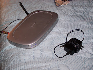
Exhibit A: The perpetrator and accomplice in tonight's little 'challenge'.

I had spent the better part of TWO HOURS trying to fix something that wasn't the problem in the first place.

And to add insult to injury, all I had to do was double check that the router had power.

That's my lesson for the evening. With my problem solved, I've had a good laugh at my own expense (I definitely earned it).

And the next time technology goes 'sproing!' on you, no matter what the technology, take a deep breath, and make sure you don't jump to any conclusions.

Sometimes the solution is really as simple as double checking to make sure the lights are on....

Joanthan Landeros


www.ketivtech.com

Monday, July 06, 2009

Autodesk Showcase - Recalling Your Past (Materials)

"I hear and I forget. I see and I remember. I do and I understand"
Confucius

In my last few posts, I've talked about creating new materials, primarily by using bump maps. But there's so much more you can start doing. I've already started toying with things like highlights, reflection blurs, and highlight colors among other things. Already I find myself thinking of all the things I can start blogging.

But before I start talking about that, I decided that I wanted to talk about how we can take the material we created, and make it available to other Showcase renderings I'm going to create in the future. For example, here's the 'Rippled Metal' I used in my previous post HERE


(Click to Enlarge)

The downside of what I've talked about so far, is that this material is only available to the file I created it in. material I've created in. In other words, I can't easily access it from another file. Some of these materials can take a while to create, and for reasons such as consistency, and a desire not to have to do the same thing over again, it's very desirable to make this material available elsewhere.

The answer: A Materials Library.

This is a way to create an external library where I can access this material I created.

So, with all that done, what are the steps

First, I bring up my materials list by going to the Materials>Materials pulldown, or just hitting 'M'.

I've already created the material, but I should give it a proper name that will help me pick it out of the library in the future.


(Click to Enlarge)

First, I right cilck on the material, and choose 'Rename'. I enter the proper name, in this case, I'm calling it 'Rippled Metal'. One word of warning. Showcase keeps the materials in alphabetical order. So if the material was named 'Steel xxx', and you rename it to 'Black Steel' (for example), it will reorder. It might make you gasp a second.

This can surprise you if it moves out of sight. Don't worry, just scroll back to where it reordered. Don't forget to start breathing again. :-)

(Click to Enlarge)

Now with the material renamed (and relocated), right click on it, and choose 'Save to Library'. Since we've not created a library yet. Our only option is to create a new library. Which we'll do.


(Click to Enlarge)

Showcase will ask us where we want to create the library. I'm using a laptop, so I put it in the 'My Documents' folder, where I've created a folder called 'My Showcase Materials'. If you're in a collaborative environment, you might want to consider a shared folder on the network. This way you can keep all the materials in a separate location where it's backed up.


(Click to Enlarge)

Now, Showcase asks me for the category to create for the file. this is another way to organize your materials (plastics, metals, fabrics, for example). Here I've just called it 'Textured Metals'


(Click to Enlarge)

That's it! You've not got a library that can be easily accessed in new files!


(Click to Enlarge)

There is one last thing. Showcase by default, names your library after the path it's located in. You might or might not want that. If you right click on the path in Showcase, you can rename the library to anything you'd like. Note, this is also where you can add, remove, and edit the library, categories, etc.


(Click to Enlarge)

Now you're ready to go!


(Click to Enlarge)

I've got some more materials blogs planned soon, check back for those a little later!

In closing, you might ask why I don't put it in the install directory, with the rest of my Showcase materials?

For me, there's a very specific reason I don't. I done that with other programs in the past, and when I've upgraded from one version to another. I sometimes forget to back up those files before I delete the directories. I've lost quite a bit of data that way (for some reason I never learn my lesson on that one). So this is how I project myself, from... well, myself.

Have a good week everyone!