Design is not making beauty, beauty emerges from selection, affinities, integration, love.
Louis Kahn
Once again Marion Landry has come through with a great post on selecting objects in Autodesk Showcase.
While selecting objects in Showcase isn't a difficult task, there are always tricks that will make it even easier.
Check out some of Marion's tricks that make selecting objects Showcase a snap!

Showing posts with label Autodesk Showcase. Show all posts
Showing posts with label Autodesk Showcase. Show all posts
Wednesday, January 08, 2014
Monday, November 04, 2013
Cannot Save File in Autodesk Showcase 2014. Try this Hotfix!
He who helps in the saving of others, Saves himself as well.
Hartmann Von Aue
Last week, I ran into a peculiar issue with Autodesk Showcase 2014. A user was running into an error that wasn't allowing them to save a particular file.
The error just stated that the scene could not be saved.
My first reaction is, "Uh oh. This file is probably hosed."
But before I began the funeral procession for a poor, corrupted file, I decided it was worth a little research to see if maybe, just maybe, there might be some why to save our lost file.
It's a good thing I took the time to do a little research. When I did, my search located a hotfix for Showcase 2014 that fixed this very issue!
It can be found at the link here!
Am I glad I took that little bit of time to research!
The service pack was installed, and the system was happily saving documents again!
So what's the moral of the story? Don't assume too much. It took me less than 10 minutes of Google searching to find the solution.
Even a few minutes search can be helpful! The file you save, may be your own!
And if you're running into this particular issue in Autodesk Showcase 2014, make sure you install this hotfix!
Hartmann Von Aue
Last week, I ran into a peculiar issue with Autodesk Showcase 2014. A user was running into an error that wasn't allowing them to save a particular file.
The error just stated that the scene could not be saved.
| Oh dear, this can't be good! |
But before I began the funeral procession for a poor, corrupted file, I decided it was worth a little research to see if maybe, just maybe, there might be some why to save our lost file.
It's a good thing I took the time to do a little research. When I did, my search located a hotfix for Showcase 2014 that fixed this very issue!
It can be found at the link here!
Am I glad I took that little bit of time to research!
The service pack was installed, and the system was happily saving documents again!
So what's the moral of the story? Don't assume too much. It took me less than 10 minutes of Google searching to find the solution.
Even a few minutes search can be helpful! The file you save, may be your own!
And if you're running into this particular issue in Autodesk Showcase 2014, make sure you install this hotfix!
Sunday, September 08, 2013
Take Your Best (Animated) Shot in Autodesk Showcase
“Cinema is a matter of what's in the frame and what's out”
Martin Scorsese
In my post last week, I talked about creating static camera shots inside of Autodesk Showcase.
But Showcase can also create animated shots too!
In these shots, different camera animations can be created that make the camera zoom, orbit, or pan across the object in the scene.
By using these effects, a compelling 'eye catching' scene can be created. One that will really grab the attention of the intended audience.
So how can a cinematic shot be created?
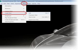
Just like in my previous post, go to Story>Create Shot. Options to create an Orbit, or "Start to End" Shot are available.
Now, the Properties dialog box shows up, and I can begin tweaking my animation to suit the needs for a shot.
There's a lot of different things that can be tweaked, so I created the image below.
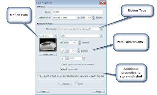
All of these settings can be adjusted to create different types of animations, all giving a different type of effect.
For example:
Motion Type switches the motion between Still, Cinematic, and Start to End. Depending on the type of motion selected, animations for Orbit, Pan, Zoom In/Out, etc. These have the added bonus of being able to capture a point along the camera path to set the view.
Motion Path controls the path for the camera, creating the desired camera effect for the animation using a point along the path.
Path Dimensions allow the camera path to be adjusted by typing in the angle, position, and duration of the camera path.
By adjusting these settings, the animation can be changed and just like before, mutliple animations can be created and animated together to create a longer presentation!
Give it a try and experiment! And check out the video below!
Martin Scorsese
In my post last week, I talked about creating static camera shots inside of Autodesk Showcase.
But Showcase can also create animated shots too!
In these shots, different camera animations can be created that make the camera zoom, orbit, or pan across the object in the scene.
By using these effects, a compelling 'eye catching' scene can be created. One that will really grab the attention of the intended audience.
So how can a cinematic shot be created?
Just like in my previous post, go to Story>Create Shot. Options to create an Orbit, or "Start to End" Shot are available.

Now, the Properties dialog box shows up, and I can begin tweaking my animation to suit the needs for a shot.
There's a lot of different things that can be tweaked, so I created the image below.

All of these settings can be adjusted to create different types of animations, all giving a different type of effect.
For example:
Motion Type switches the motion between Still, Cinematic, and Start to End. Depending on the type of motion selected, animations for Orbit, Pan, Zoom In/Out, etc. These have the added bonus of being able to capture a point along the camera path to set the view.
Motion Path controls the path for the camera, creating the desired camera effect for the animation using a point along the path.
Path Dimensions allow the camera path to be adjusted by typing in the angle, position, and duration of the camera path.
By adjusting these settings, the animation can be changed and just like before, mutliple animations can be created and animated together to create a longer presentation!
Give it a try and experiment! And check out the video below!
Thursday, September 05, 2013
An Autodesk Showcase Guest Video - Adding Bloom Effects to a Scene
“From the withered tree, a flower blooms”
Zen Proverb
As this week draws to a close, I wanted to share another great video from Marion Landry's YouTube Channel.
This one is on creating bloom effects, or the "glowing" effect that can is sometimes visible.
It's another effect that can make a scene standout, and it's definitely worth taking a look at!
Take a look at this video, and the other Autodesk Showcase videos on Marion's YouTube Channel!
Monday, September 02, 2013
Take Your Best (Still) Shot in Autodesk Showcase
“The camera can photograph thought”
Dirk Bogarde
I've done it many a time before.
I've created a series of images of a scene in Autodesk Showcase, only to realize I don't have an easy way to reproduce one at a later date. I have to carefully arrange the shot again, making sure I got all the camera angles right and then recreate it.
This isn't the fault of Showcase, it's a result of me getting anxious, and forgetting to use a tool that can save me a lot of time and trouble.
Camera shots.
Camera shots in Showcase allow camera angles to be saved and recalled, along with some built in camera effects, camera angles, and in Showcase 2014, depth of field settings.
So how are camera shots accessed?
The first place it can be found is in the Story>Camera Shot pulldown. The other is the hotkey "T" which is what I prefer to use.
Choosing Still from the Camera Shot pulldown, or using the hotkey "Ctrl+T" will take a still shot of the current camera position and camera properties.
This is how a shot can be saved for later!
But there's more that can be done! Right clicking on a shot will bring up options that allow the shot to be changed. But here, I'm just going to choose Properties.
The properties screen will allow for the changing of different settings for the shot.
These include the transition type between shots (Still, Animate, Cut to Shot), and duration, as well as Animation types, which I'll cover in my next post.
But feel free to experiment with these, and get an idea how they work!
And for a video version of this post, take a look below!
Dirk Bogarde
I've done it many a time before.
I've created a series of images of a scene in Autodesk Showcase, only to realize I don't have an easy way to reproduce one at a later date. I have to carefully arrange the shot again, making sure I got all the camera angles right and then recreate it.
 |
| I like this shot, but how do I recall it later? |
Camera shots.
Camera shots in Showcase allow camera angles to be saved and recalled, along with some built in camera effects, camera angles, and in Showcase 2014, depth of field settings.
So how are camera shots accessed?
The first place it can be found is in the Story>Camera Shot pulldown. The other is the hotkey "T" which is what I prefer to use.
 |
| Accessing the shots |
This will bring up the toolbar that shows the existing shots.
 |
| The shots panel in the upper left. |
Choosing Still from the Camera Shot pulldown, or using the hotkey "Ctrl+T" will take a still shot of the current camera position and camera properties.
This is how a shot can be saved for later!
 |
| A new shot created |
 |
| Choose properties |
These include the transition type between shots (Still, Animate, Cut to Shot), and duration, as well as Animation types, which I'll cover in my next post.
But feel free to experiment with these, and get an idea how they work!
And for a video version of this post, take a look below!
Thursday, August 01, 2013
Getting Rid of the "Black Streaks" in an Autodesk Showcase Scene
I believe in the kingdom come
Then all the colors will bleed into one
U2 - "I Still Haven't Found What I'm Looking For"
Sometimes, there really is "one magic" setting that can obtain the desired result. In Autodesk Showcase, I've found that one of these is setting the clipping plane.
Sometimes, when a model is imported into a Showcase scene, black triangular streaks will appear across the model.
They shouldn't be there, they're not right, and they're ugly.
They're actually caused by Showcase not being able to sort the faces. The back face is actually bleeding through the face in front of it.
Fortunately, they can be easily cleaned up with just one setting.
The setting is found in File>Settings>Scene Settings
Once the dialog box opens, the setting I'm after is: Distance from camera to near clipping plane:
By increasing the number, the distance to the clipping is changed and the faces can set the correct order.
In this case, increasing the setting to 2.000cm makes everything as it should be. Of course different scenes may require different settings, so if you if you're working with your own scenes, you may have to try a couple of different numbers.
But just that setting alone, can make a huge difference in how a Showcase scene appears in the end.
For a fantastic explanation of this, take a look at the video below created by Marion Landry. She's the person who originally taught me this great trick, and she's definitely got the definitive video in my opinion!
Then all the colors will bleed into one
U2 - "I Still Haven't Found What I'm Looking For"
Sometimes, there really is "one magic" setting that can obtain the desired result. In Autodesk Showcase, I've found that one of these is setting the clipping plane.
Sometimes, when a model is imported into a Showcase scene, black triangular streaks will appear across the model.
 |
| What are those? They're not supposed to be there! |
They shouldn't be there, they're not right, and they're ugly.
They're actually caused by Showcase not being able to sort the faces. The back face is actually bleeding through the face in front of it.
Fortunately, they can be easily cleaned up with just one setting.
The setting is found in File>Settings>Scene Settings
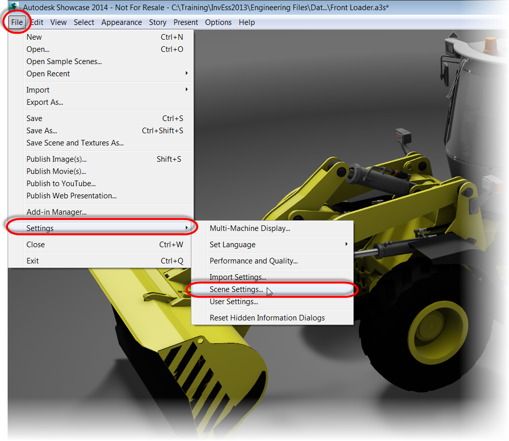 |
| Getting to the setting I need |
Once the dialog box opens, the setting I'm after is: Distance from camera to near clipping plane:
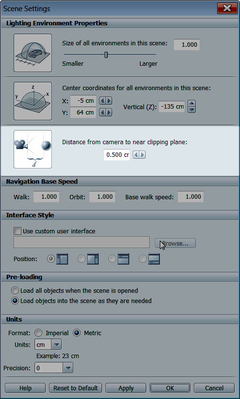 |
| The setting to change is highlighted. |
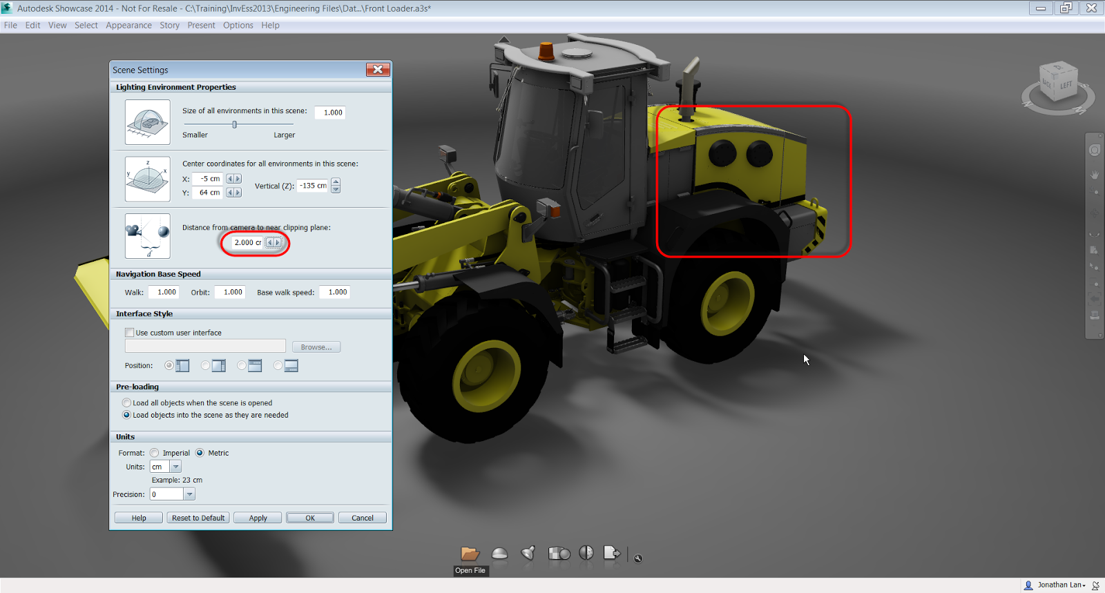 |
| Much better! |
In this case, increasing the setting to 2.000cm makes everything as it should be. Of course different scenes may require different settings, so if you if you're working with your own scenes, you may have to try a couple of different numbers.
But just that setting alone, can make a huge difference in how a Showcase scene appears in the end.
For a fantastic explanation of this, take a look at the video below created by Marion Landry. She's the person who originally taught me this great trick, and she's definitely got the definitive video in my opinion!
Tuesday, June 04, 2013
A Guest Video on Depth of Field in Autodesk Showcase 2014
It is not length of life, but depth of life.
Ralph Waldo Emerson
I wish I could say that I had I was the absolute guru in Autodesk Showcase. I wish I could be, to use the corporate buzzword, "the single point of truth".
But I'm not, and it would be foolish to presume that I am. There are always things for me to learn and make myself better.
Fortunately, there are plenty of generous Showcase users out in "the 'Verse" who are willing to share information with the rest of the user community.
For this midweek post, I'm sharing some excellent videos shared by Marion Landry on her YouTube channel.
These videos have some excellent tips on using Depth of Field in Autodesk Showcase, particularly with some workflows and tips on using Depth of Field in Ray Tracing and Hardware Rendering.
I also like her tips on using shots to save different depth of field views using both hardware rendering and ray tracing, as well as using them in animations!
Take a look at the videos! They're a great help!
Showcase Tips & Tricks: Showcase 2014 Depth of Field Part 1
Showcase Tips & Tricks: Showcase 2014 Depth of Field Part 2
Showcase Tips & Tricks: Showcase 2014 Depth of Field Part 3
Thursday, May 09, 2013
Changing Autodesk Showcase Model Orientation After Importing from Autodesk Inventor - A Guest Video
“For many people, one of the most frustrating aspects of life is not being able to understand other people's behavior.”
Anonymous
Autodesk Showcase has a lot of tricks up it's sleeve when importing models. But that leaves the challenge of knowing when to use which trick.
One challenge, I know I've always faced is importing Autodesk Inventor Constraints as Behaviors in Showcase. I don't do it often, so I find that I figure out how to use them for a scene, but then I don't use them for a while.
The next time I need to use them, I've managed to forget everything I learned, so I have to relearn it again!
But as many a teacher has reminded me over the years, "It's not about knowing information, it's about knowing where to find information".
So here is another guest video by Marion Landry on how to use import settings in Showcase to make sure you get the results you want! It gave me some more ideas on import tricks, and I'm sure others will find it helpful too!
Thank you, Marion!!
Sunday, April 28, 2013
Using the New "Depth of Field" Setting in Autodesk Showcase 2014
“There is only you and your camera. The limitations in your photography are in yourself, for what we see is what we are.”
Ernst Haas
One of the challenges in using Autodesk Showcase is getting the rendering, and particular, the focus of the rendering stand out.
Its one of the reasons that many times, I don't like putting the subject of a rendering "in it's natural environment". It looks like it belongs there, and it just disappears.
But on the other hands, there are definitely times that there's a benefit to putting a subject where it belongs, in a shop, in a lab, or on a street, for example, instead of in an "empty photo room".
One of the new tools added to Autodesk Showcase 2014 is the "Depth of Field" setting, which, like the F-Stop on a camera, controls how the scene is focus, and how objects "blur away" as they get further from the "lens" in the scene.
In the scene I'm using here, I've taken a picture of the Planes of Fame B-25 Mitchell, created a backdrop, and inserted two engines, which are models I downloaded from GrabCAD at the link here.
I'm not using any depth of field settings. I'm just using the backdrop "as is".
Everything is in focus. And while it might be easy to look at the engines in the foreground, it's also possible that the person viewing the image might not be immediately drawn to the engines
With the Depth of Field setting, the background can be blurred and the focus of the scene can quickly be places on the engine. So how does depth of field work?
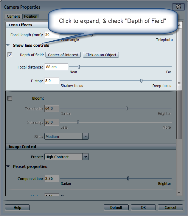
I start by going to View>Camera Properties.
Once the Camera Properties come up, click "Show More Controls" under lens effects. "Depth of Field" will appear there, check the box to enable it.
Now, I can select "Click on Object", and choose the engine closest to the foreground on my screen. This tells Showcase where I'm "aiming the camera".
Once this is done the sliders for Focal Distance and F-Stop can be used to change the focus of the scene, and bring one object into focus, and blurring the others to bring out the desired effect.
Once the desired effect is achieved, select OK to accept the new result!
So go ahead and give these settings a try. Like so many settings in Showcase, there's not a right or wrong way, just what you like!
And for the steps in a video form, look below!
Ernst Haas
One of the challenges in using Autodesk Showcase is getting the rendering, and particular, the focus of the rendering stand out.
Its one of the reasons that many times, I don't like putting the subject of a rendering "in it's natural environment". It looks like it belongs there, and it just disappears.
But on the other hands, there are definitely times that there's a benefit to putting a subject where it belongs, in a shop, in a lab, or on a street, for example, instead of in an "empty photo room".
One of the new tools added to Autodesk Showcase 2014 is the "Depth of Field" setting, which, like the F-Stop on a camera, controls how the scene is focus, and how objects "blur away" as they get further from the "lens" in the scene.
In the scene I'm using here, I've taken a picture of the Planes of Fame B-25 Mitchell, created a backdrop, and inserted two engines, which are models I downloaded from GrabCAD at the link here.
I'm not using any depth of field settings. I'm just using the backdrop "as is".
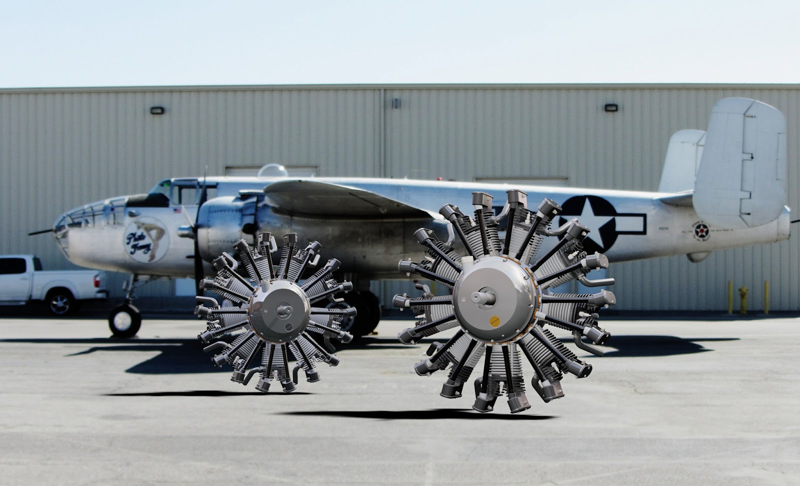 |
| The two engines place in the scene with the B-25 |
Everything is in focus. And while it might be easy to look at the engines in the foreground, it's also possible that the person viewing the image might not be immediately drawn to the engines
With the Depth of Field setting, the background can be blurred and the focus of the scene can quickly be places on the engine. So how does depth of field work?
I start by going to View>Camera Properties.
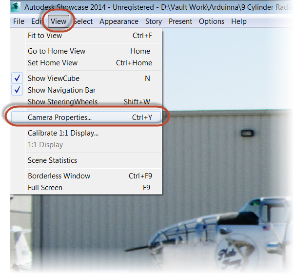 |
| Choosing Camera properties. |
 |
| Choosing depth of field. |
Now, I can select "Click on Object", and choose the engine closest to the foreground on my screen. This tells Showcase where I'm "aiming the camera".
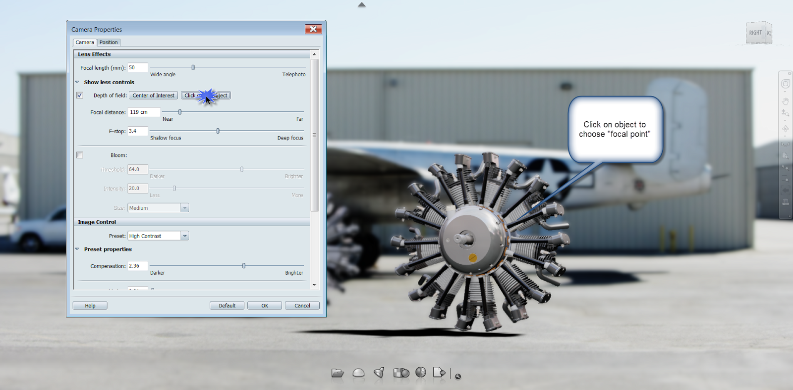 |
| Choosing the object of focus |
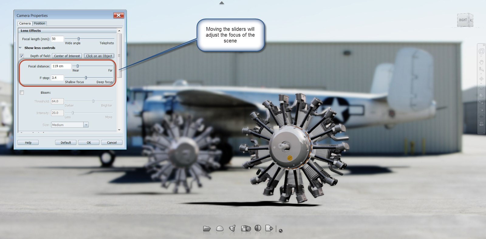 |
| Changing the Depth of Field settings |
Once the desired effect is achieved, select OK to accept the new result!
 | |
| The completed result |
So go ahead and give these settings a try. Like so many settings in Showcase, there's not a right or wrong way, just what you like!
And for the steps in a video form, look below!
Thursday, March 28, 2013
Keeping up with the Power Curve - 2014 System Requirements for Autodesk Design Suites
I have the power!
He-Man
It looks like Autodesk's 2014 based products are on the horizon.
And while I haven't seen any dates indicating when that's going to be, I've noticed that the system requirements are up on Autodesk's website.
I've noticed that it looks like Windows 8 is getting support, which is good news for many, I'm sure!
So if you're thinking of going to the 2014 based products, and you're interested in seeing if your hardware is up to snuff, check out the link HERE and see if how your hardware stacks up!
He-Man
It looks like Autodesk's 2014 based products are on the horizon.
And while I haven't seen any dates indicating when that's going to be, I've noticed that the system requirements are up on Autodesk's website.
I've noticed that it looks like Windows 8 is getting support, which is good news for many, I'm sure!
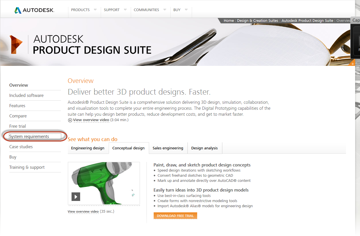 |
| The Product Design Suite Page |
So if you're thinking of going to the 2014 based products, and you're interested in seeing if your hardware is up to snuff, check out the link HERE and see if how your hardware stacks up!
Wednesday, March 13, 2013
Changing Model Orientation in Autodesk Showcase AFTER it's Imported
“Every orientation presupposes a disorientation.”
Hans Magnus Enzensberger
Last week, my post showed how the orientation of a model could be changed as it was being imported into Autodesk Showcase. (You can check out that post here)
But what if the file has already been imported? Marion Landry of Autodesk shared a tip via the video comments that pointed it's possible after import too! It's definitely a valuable little jem of a tool I didn't know was there!
I'm starting out with my model already imported sideways. So there's no chance for me to fix it using the methods I used in my previous post.
But to fix it afterward, all I have to do is go to the File>Import>Import Status Window menu, or just hit the "I" key.
Once the Import Status window appears, I'm going to right click on the name of the imported model under "Source Files". Choose "3D Model Properites.
It's important to right click on the imported , or 3D Model Properties won't appear!

Now, I get the "Original 3D Model Properties" dialog, where I can change the units, and the "Original Up Axis". Choosing "+Z", the model is reoriented!

So there it is, a quick way of changing orientation after a model is imported. Thanks to Marion for taking a few minutes to show this valuable tip!
Hans Magnus Enzensberger
Last week, my post showed how the orientation of a model could be changed as it was being imported into Autodesk Showcase. (You can check out that post here)
But what if the file has already been imported? Marion Landry of Autodesk shared a tip via the video comments that pointed it's possible after import too! It's definitely a valuable little jem of a tool I didn't know was there!
I'm starting out with my model already imported sideways. So there's no chance for me to fix it using the methods I used in my previous post.
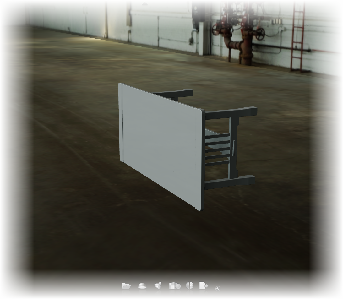 |
| It's in sideways, and now how to fix it? |
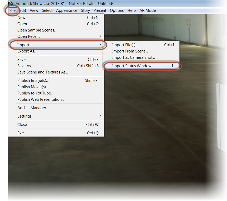 |
| Locating the import status window |
Once the Import Status window appears, I'm going to right click on the name of the imported model under "Source Files". Choose "3D Model Properites.
It's important to right click on the imported , or 3D Model Properties won't appear!
Now, I get the "Original 3D Model Properties" dialog, where I can change the units, and the "Original Up Axis". Choosing "+Z", the model is reoriented!
So there it is, a quick way of changing orientation after a model is imported. Thanks to Marion for taking a few minutes to show this valuable tip!
Sunday, March 10, 2013
Righting the World - Changing Import Settings for Autodesk Showcase
“In the time of my life, I need more time just to make things right.”
Sometimes a that clanking sound I hear is a wrench hitting hitting my proverbial works.
And when importing files into Autodesk Showcase from another system, the import orientation (or disorientation), can be that wrench.
Take this for example. Sometimes a file imports, and instead of being right side up, it's completely on its side.
The easy way to fix it is to use the Transform Handles in Autodesk Showcase to correct the problem. But what if there are positional alternatives that need to be preserved? Rotating with Transform handles can sometimes mean rebuilding the alternatives.
Fortunately, there is another option when importing files.
First, when in Showcase, choose File>Import>Import Files
When the import dialog box opens, choose the "Settings" button.
Once the import settings dialog box appears, the setting for "Original up axis" can be seen. This is where I can tell Showcase "which way is up".
Note that you can also see the "Import Representations" checkbox in this dialog box. So Inventor representations can be imported in as well.
If I take a quick look at the file in Inventor, I can see the +Z-axis corresponds to the top of the table.

Seeing this, I'll choose the +Z radio button, and import the files.
The file will import, and the orientation will correspond to the "up axis" I selected.
And if you're looking for the usual video that accompanies my blog posts, here you go!
Sometimes a that clanking sound I hear is a wrench hitting hitting my proverbial works.
And when importing files into Autodesk Showcase from another system, the import orientation (or disorientation), can be that wrench.
Take this for example. Sometimes a file imports, and instead of being right side up, it's completely on its side.
 |
| Blast it! |
| Rotating with Transform Handles is sometimes an option |
First, when in Showcase, choose File>Import>Import Files
 |
| Preparing to import a file. |
 |
| Choosing the import settings |
Once the import settings dialog box appears, the setting for "Original up axis" can be seen. This is where I can tell Showcase "which way is up".
Note that you can also see the "Import Representations" checkbox in this dialog box. So Inventor representations can be imported in as well.
 |
| Changing the orientation |
If I take a quick look at the file in Inventor, I can see the +Z-axis corresponds to the top of the table.
Seeing this, I'll choose the +Z radio button, and import the files.
 |
| Selecting the +Z option |
 |
| Oriented with representations created as alternatives! |
And if you're looking for the usual video that accompanies my blog posts, here you go!
Tuesday, March 05, 2013
Bring Autodesk Inventor's Positional Representation into Autodesk Showcase
William Shakespeare
When designing, there are times that alternate positions for components must be shown to ensure the design will perform as intended.
This might be an arm extended and retracted, or a door or drawer opened, and closed.
There are also times those alternate positions need to be shown in a rendered view to properly convey the design intent outside of the design product.
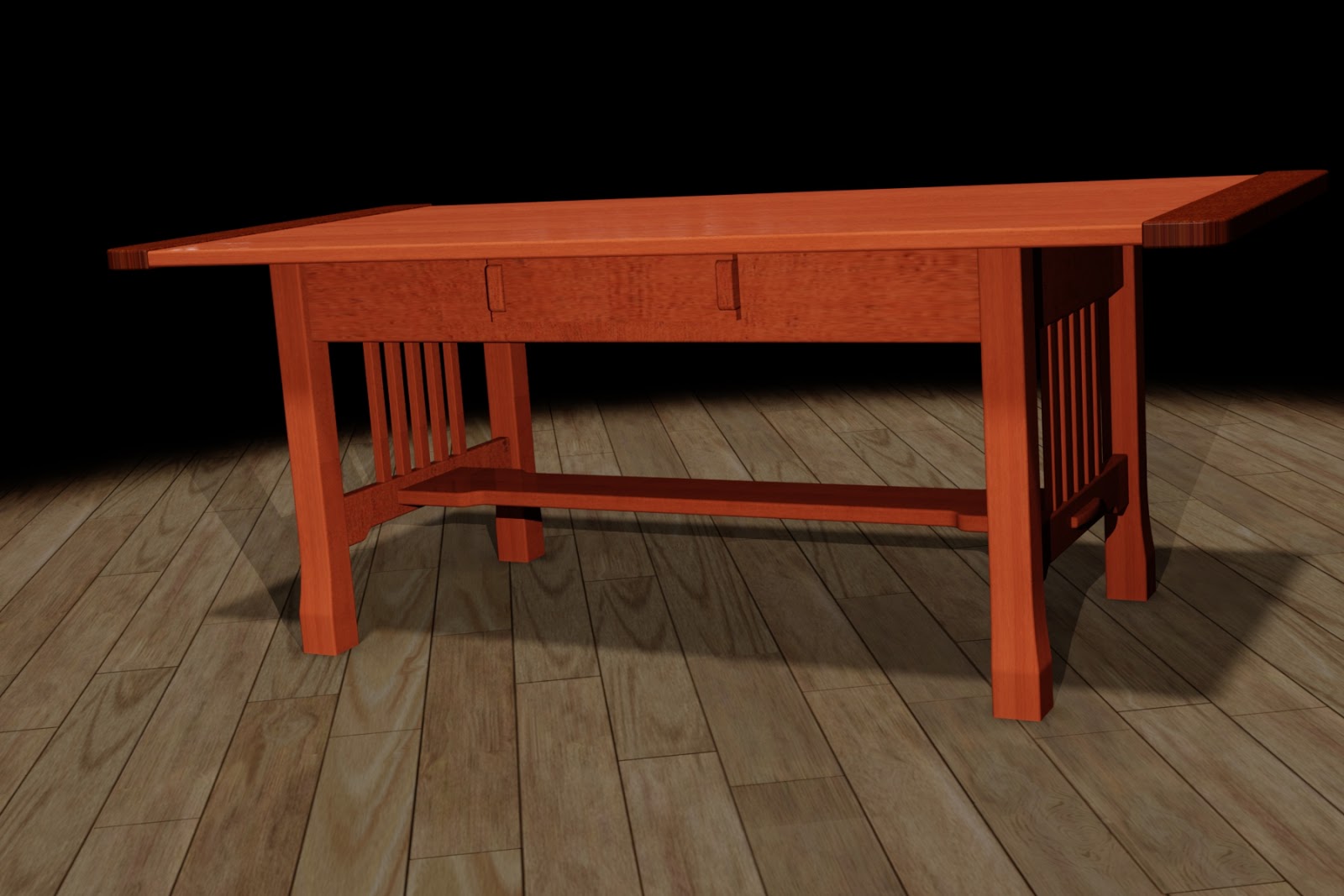
When using Autodesk Inventor, Positional Representations are used to accomplish this task in design. For example, here I'm showing a coffee table with drawer open, and drawer closed positional representation. (For instructions on how to create a positional representation, check out my previous post here)
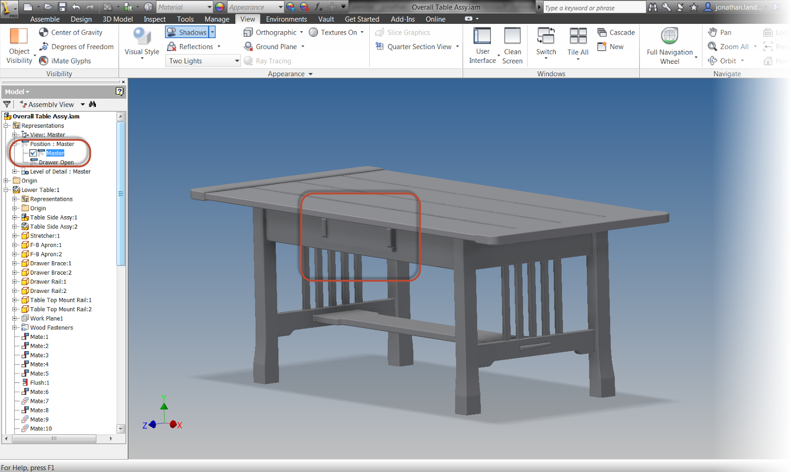 |
| A positional representation showing a drawer closed |
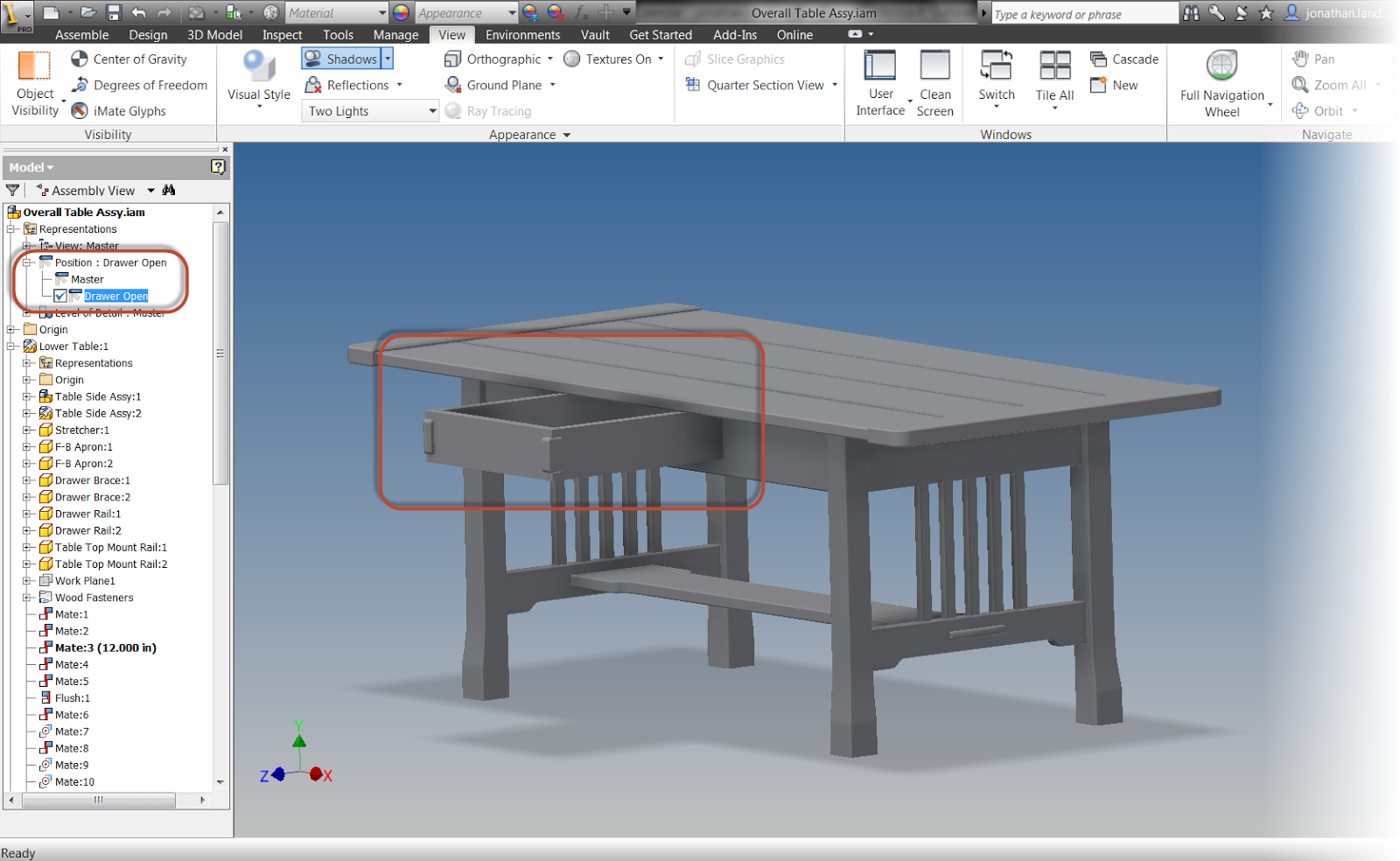
Autodesk Showcase uses Alternatives to create alternate positions for the renderings. Here is the same table shown with alternatives in Showcase
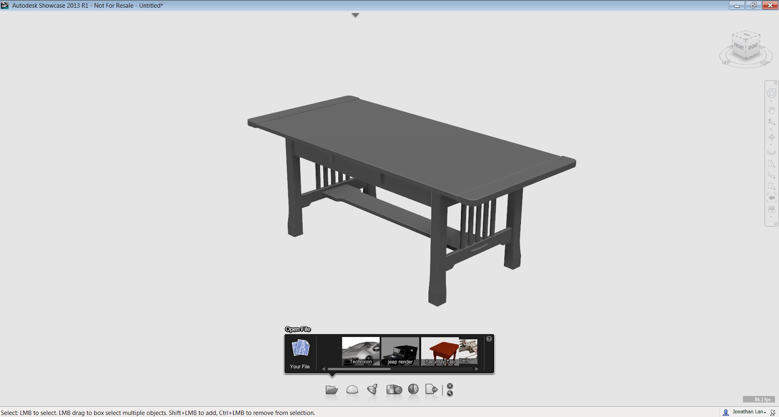 |
| The model is imported and ready with the drawer closed |
 |
| The alternative with the drawer open is already created. |
Fortunately, Inventor and Showcase has a "Suite Workflow" that allows the representations created in Inventor, to create alternatives in Showcase.
I'm going to begin with my coffee table open in inventor, then I'll click on the Application Icon (The big "I"), I choose the "Suite Workflows", then choose, "Showcase Realistic Presentation".
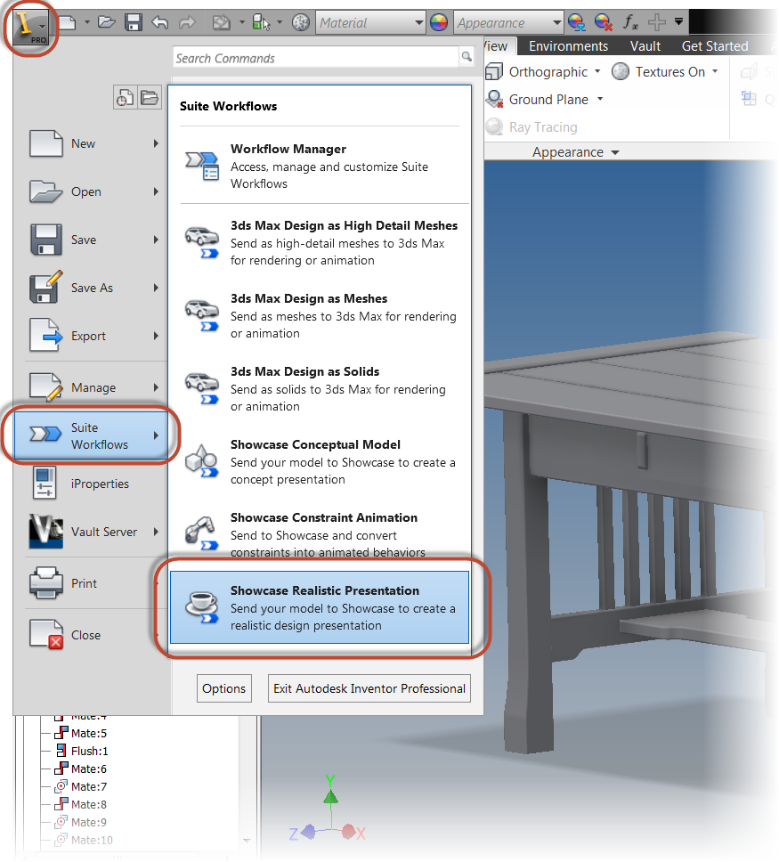 |
| Starting the representation |
A dialog box appears that describes what this setting will do. I'm going to choose the "Settings" button to make changes to how the model appears on import.
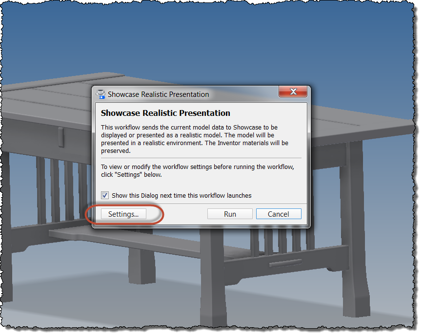 |
| Selecting the settings for import |
I do like to set the "Environment... Plane Level" setting to "At bottom of the model". While your settings may vary, this setting is works best for the models that I create.
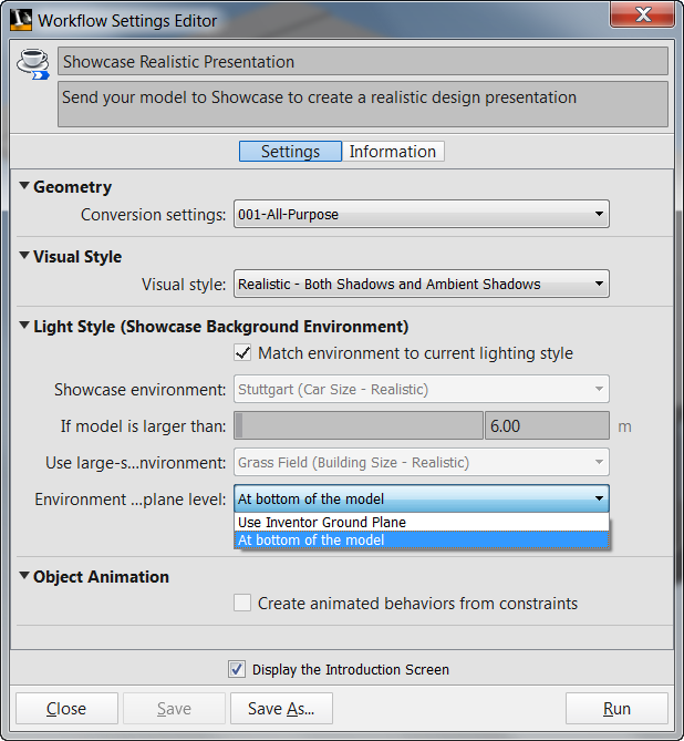 |
| Workflow Settings |
Now I go ahead and click "Run".
 |
| Pulling the trigger and running! |
The model will process, and will open in Showcase. Both alternatives are created by the positional representations
Now all I have to do is apply the desired materials and lights in Showcase, and finish creating my model in Showcase. No recreation of the drawer open, or drawer closed. Just use what Inventor provided to Showcase!
 |
| A quick rendering in Showcase with the drawer close |
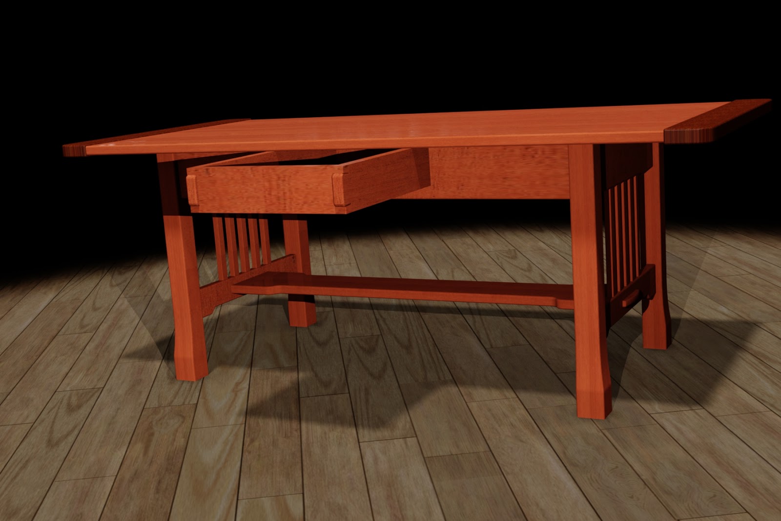 |
| The same scene with the drawer open via the alternative. |
And to see the steps in a video format, just take a look below!
Wednesday, February 27, 2013
A Guest Video - Creating Environments in Autodesk Showcase
“Find the good. It's all around you. Find it, showcase it and you'll start believing in it.”
Jesse Owens
I wish I could say I had the wherewithal to find every last tip and trick there was to find in Autodesk Showcase. But alas, I just can't quite do it.
One of those items that has always been on my "I'll get to that some day" list is the creation of custom environments. I've always known that there are a couple of tricks to it that I needed to learn, but with so many things, I never got around to it.
Thankfully, while searching one of my favorite Autodesk Showcase channels on YouTube, run by Marion Landry, I found a great video on creating custom environments.
Not only did it answer a lot of the questions I never got around to looking into myself, it also had links to Openfootage.net, which has some great hdr images that can be downloaded and used to create custom environments. And the best part is they're all free (although donations are accepted).
So here is Marion's video. Take a look and enjoy. This is one of the best videos I've seen for those of us who want to know how to create custom environments in Showcase.
Jesse Owens
I wish I could say I had the wherewithal to find every last tip and trick there was to find in Autodesk Showcase. But alas, I just can't quite do it.
One of those items that has always been on my "I'll get to that some day" list is the creation of custom environments. I've always known that there are a couple of tricks to it that I needed to learn, but with so many things, I never got around to it.
Thankfully, while searching one of my favorite Autodesk Showcase channels on YouTube, run by Marion Landry, I found a great video on creating custom environments.
Not only did it answer a lot of the questions I never got around to looking into myself, it also had links to Openfootage.net, which has some great hdr images that can be downloaded and used to create custom environments. And the best part is they're all free (although donations are accepted).
 |
| My own environment created from an image on Openfootage.net |
So here is Marion's video. Take a look and enjoy. This is one of the best videos I've seen for those of us who want to know how to create custom environments in Showcase.
Wednesday, February 20, 2013
A Guest Video on Adjusting Shadow Cutoff Settings in Autodesk Showcase
“Hopefully my experience can help a little bit. I'm just a small piece of the puzzle."
Ed Jovanovski
Over the years that I've strolled this earth, I've come to learn that just as important as knowing something, is knowing where to find something.
One of my favorite places for finding information that help improve my skills in Autodesk Showcase is Marion Landry's YouTube Channel.
Marion has some fantastic Showcase tips and I've learned many a new trick that have helped make my renderings better.
In this video, she shows how to adjust shadows for the best appearance, and prevent them from getting "cut off" and just not looking right.
Have a look at her video below! Thank you Marion for sharing!
Sunday, December 16, 2012
Matching Colors in Autodesk Showcase
“Don't miss all the beautiful colors of the rainbow looking for that pot of gold.”
Unknown
If you want to know how important getting the proper color of a logo can be. Get it wrong and see how quickly the Marketing Department comes looking for you.
The truth is it can be very important. For things such as color schemes and logos, it can be critical. Company "red" is not just "red". It's a specific red, or blue, or yellow.
When working in Autodesk Showcase, there have been a few times where I've needed to use a specific color. And if it really is that important, I'll ask for the RGB (Red, Green, Blue) values of the color.
Many times, the Marketing Department has those values, and can provide them for you.
But I recently I ran into a case where I needed to match the color of a logo as closely as possible, and and I didn't have the RGB values to work with. So what did I do?
I could have played with the color until I matched it by eye, but that can be time consuming to do, and I wanted to get as close as I could, as quickly as I could.
Fortunately, when editing a color, showcase has an "eye dropper" icon that lets you select and existing object, and "paint" it with that color.
I was able to use it to select the object I needed to match the logo with the eyedropper, and "paint" the object with that color. It worked like a charm!
Of course this isn't as accurate as having the RGB values. But when I couldn't get the RGB values, this was more than adequate to get me what I needed! It also saved me a huge amount of time because now I didn't have to finesse the color into play.
So for that, Here's a quick video on how I used this nice little trick
Unknown
If you want to know how important getting the proper color of a logo can be. Get it wrong and see how quickly the Marketing Department comes looking for you.
The truth is it can be very important. For things such as color schemes and logos, it can be critical. Company "red" is not just "red". It's a specific red, or blue, or yellow.
| The KETIV logo. It's not just "red". It's got a specific RGB value. |
When working in Autodesk Showcase, there have been a few times where I've needed to use a specific color. And if it really is that important, I'll ask for the RGB (Red, Green, Blue) values of the color.
Many times, the Marketing Department has those values, and can provide them for you.
But I recently I ran into a case where I needed to match the color of a logo as closely as possible, and and I didn't have the RGB values to work with. So what did I do?
I could have played with the color until I matched it by eye, but that can be time consuming to do, and I wanted to get as close as I could, as quickly as I could.
Fortunately, when editing a color, showcase has an "eye dropper" icon that lets you select and existing object, and "paint" it with that color.
 |
| Edit the color by right clicking on it, and choose the eyedropper |
Of course this isn't as accurate as having the RGB values. But when I couldn't get the RGB values, this was more than adequate to get me what I needed! It also saved me a huge amount of time because now I didn't have to finesse the color into play.
So for that, Here's a quick video on how I used this nice little trick
Wednesday, November 21, 2012
Accent Lights - An Autodesk Showcase Guest Video
“He has suffused the entire design with a light and transparency that is truly extraordinary.”
Charles Pierce
I know I've been featuring a lot of videos on Autodesk Showcase from Marion Landry's YouTube Channel, but the fact is she's keeps putting out fantastic material.
In this video Marion has created, she provides us with some great tips on using accent lighting in Autodesk Showcase.
I learned quite a few tricks by watching what she's done, and I'll definitely review this video later, as well as keep a close eye on her channel!.
Here's the video below on this tip!
And for those out there that are heading to Autodesk University next week, I'll see you there! I'm getting all my things in order to arrive Monday. If you're going, I'll see you there!
Thursday, November 15, 2012
And Yet Again, All for Fun - The 8 Sided Die
"DIE, n. The singular of "dice." We seldom hear the word, because there is a prohibitory proverb, "Never say die.""
Ambrose Bierce
This seems to have become a Friday series. The last few weeks I've placed a model of a gaming die on my blog, and talked about the process I went through making each one.
It stared out as a project for a website (they're the banner on the Dicehouse Games website).
Then I stated being asked if I would supply the models. So I started making them available for download and describing the steps I used here.
So far, I've created posts for the 20 sided die, the 10 sided die, and the 12 sided die. Now, I add the 8 sided die.
Here's the completed die as an embedded 3D dwf file. Click and drag to give it a spin!
This one is a pretty simple model to create, at least when compared to the others!
Next, I bisected the square with a line, on a plane perpendicular to the sketch I first used. It's worth noting that I later on realized that I only needed half the line, but I left the die as I started it.
Now, it's time to create a loft from the square, to one of the line's endpoints.
With half the die completed, I used the Mirror command to create the other half of the die.
That takes care of the heavy lifting! Now, I just add a fillet to break the sharp edges. Notice that I used the "All Round" option to select all the external edges at once.
Finally, the long tedious task of adding the number. This hasn't changed, its just a matter of creating a sketch with the number, and extruding it a shallow distance. At least there are fewer now!
And because I can, here's the quick rendering in Autodesk Showcase.
P.S. If you're wondering why I didn't loft from the line's endpoint, to the square, to the other endpoint, here's what happened when I tried.
Needless to say, this wouldn't have made a very good die. So I changed my approach, and used the Mirror command instead. But now you know why I created the line the way I did. It's a vestige of an aborted work process!
And of course, here are the links to download the files.
Click here for the Autodesk 360 link
Click here for the GrabCAD link
Enjoy! I hope to see some of you at Autodesk University 2012!
Ambrose Bierce
This seems to have become a Friday series. The last few weeks I've placed a model of a gaming die on my blog, and talked about the process I went through making each one.
It stared out as a project for a website (they're the banner on the Dicehouse Games website).
Then I stated being asked if I would supply the models. So I started making them available for download and describing the steps I used here.
So far, I've created posts for the 20 sided die, the 10 sided die, and the 12 sided die. Now, I add the 8 sided die.
 |
| The completed die |
Here's the completed die as an embedded 3D dwf file. Click and drag to give it a spin!
This one is a pretty simple model to create, at least when compared to the others!
- First, I sketched a square on an origin workplane. In my case, I chose the XZ workplane.
 |
| The first step that starts it all |
Next, I bisected the square with a line, on a plane perpendicular to the sketch I first used. It's worth noting that I later on realized that I only needed half the line, but I left the die as I started it.
 |
| Added the perpendicular line. I later realized I didn't need the whole line |
Now, it's time to create a loft from the square, to one of the line's endpoints.
 |
| Creating half of the die |
With half the die completed, I used the Mirror command to create the other half of the die.
 |
| Using the Mirror command to create the other half of the die |
That takes care of the heavy lifting! Now, I just add a fillet to break the sharp edges. Notice that I used the "All Round" option to select all the external edges at once.
 |
| Breaking the sharp edge |
Finally, the long tedious task of adding the number. This hasn't changed, its just a matter of creating a sketch with the number, and extruding it a shallow distance. At least there are fewer now!
 |
| The process of adding the numbers |
And because I can, here's the quick rendering in Autodesk Showcase.
 |
| And a rendering to make it look cool! |
P.S. If you're wondering why I didn't loft from the line's endpoint, to the square, to the other endpoint, here's what happened when I tried.
Needless to say, this wouldn't have made a very good die. So I changed my approach, and used the Mirror command instead. But now you know why I created the line the way I did. It's a vestige of an aborted work process!
 |
| Doh! Not what I wanted! |
And of course, here are the links to download the files.
Click here for the Autodesk 360 link
Click here for the GrabCAD link
Enjoy! I hope to see some of you at Autodesk University 2012!
Subscribe to:
Posts (Atom)