Find us on Google+ Inventor Tales: Inventor Sheet Metal
Showing posts with label Inventor Sheet Metal. Show all posts

Sunday, October 22, 2017

Using Fusion 360's "Paste New" to create Similar Parts

Before diving into my next post, I wanted to say that I'm glad the solution I shared to fix the broken threads issue in Autodesk Inventor helped so many.  When it first occurred earlier this week, I thought it was just me.  Little did I know that so many others would run into it!

I originally found the issue on the Autodesk Community, so credit where credit is due.  The link to the post where I found the information is in the original post, as well as linked here.

Now, I'm back to a little Fusion 360 work I've been doing.

As part of an ongoing project, I've been slowly building different parts here and there, mostly off of vintage prints from AirCorps Library

One of the challenges I ran into was building a model of a continuous, or piano hinge.  It's based on the AN951 standard, which has since been superseded by the MS20257 standard,

One hinge leaf.  A little examination shows how it's mate has to
vary to mesh correctly.

Modeling the hinge isn't a difficult task, building the individual hinge leaves is easy, but they need to be made to mesh correctly.   That means the hinge knuckles have to be offset, and that's where the knuckles have to be different.


But other than that, everything is the same only the hinge knuckles vary.  So it would be ideal to be able to create a new copy of the existing hinge leaf, and make the appropriate changes. 

It turns out that Fusion 360 has a functionality known as "Paste New", and it's exactly what I needed.  It will create a new, independent copy of first hinge leaf, while leaving the original alone.  That means being able to reuse as much of the design as possible, while only changing what has to be changed.

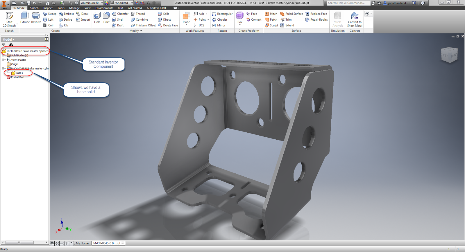
I started with an assembly with one of the leaves modeled as its own component.  You can see that in the browser..  Now it's time to make the other side of the hinge so it can be changed so it can mesh with its mating hinge leaf.
The browser with the new part modeled
 All that needs to be done is to right click on the existing component and choose "Copy".  It's just a good old Windows Copy.

Copying the part is where it all starts. 
Now move the cursor onto the modeling canvas, right click, and choose "Paste New".  A new, independent, hinge leaf can be placed and positioned. 

Pasting the new copy using the Paste New command
I'd suggest getting the part as positioned in it's "nearly" correct position.  Then you'll be able to make changes to key features, the hinge knuckles in this case.

Positioning the part. You can use the handles, or dialog box.
Now all that's left to do is activate the new copy, modify it so it meshes with the original, and assemble.  And we're off to the races!

There it is!  All done! 

So keep this in mind when you have similar components to build, and modify it for your needs.  It can really help in not recreating extra work!

Sunday, September 17, 2017

Creating a Part by Projecting Geometry from Another Part in Fusion 360

One of the goals I set  for myself is to try to spend some time every week to build something in Fusion 360.  Sometimes, all I can do is create a patter of holes, or build a few sheet metal flanges.

But I always tell myself I'll try something new in Fusion 360.  

So far, so good!

One thing I've been trying is making different parts, some of which have been sheet metal.

I've got ribs that will support a sheet metal.  The component is an aircraft trim tab.  There are two ribs at each end of the tab.

The sheet metal forming the tab will wrap around the ribs and attached via rivets.  That means that the sheet metal will be following the ribs, so why not reuse that geometry instead of trying to recreating with a lot of "measuring and calculating".

The first thing to do is to assemble the ribs in their final position and orientation.

The ribs place and oriented, ready for sheet metal.
The next step is to create a new component in the Fusion assembly and activate it.  Select it as a sheet metal part and set your sheet metal rules.

If your not sure about creating sheet metal rules, my previous post here may help.


Create a new component

Now, create a sketch, and being projecting geometry from the existing parts.  


Now project the geometry that will be used to help define the new part.  I'd recommend making it construction geometry to make sure it doesn't accidentally add itself to your part. 

Creating construction geometry to build a part.
Now sketch out the profile required.  In this case, it's the shape of the sheet metal part. 

Projected geometry to form the sheet metal profile.

Now it's a matter of creating the sheet metal flanges to the distance needed to define the part.

The sheet metal part extruded.
Now continue the process of defining the part.  This includes other features, such as extrusions and holes.

Additional features can be created by projecting from another part.
Give it a try, it can make creating another part much easier than transitioning measurements! 

Bonus tip! 

Change your part opacity by right clicking on a component and choosing "Opacity Control".  You can make the part semi-transparent and make it easier to see underlying geometry! 

Try changing Opacity to make selecting through parts easier.
Acknowledgements: 

Trim tab created from drawings accessed via my subscription to Air Corps Library.

Wednesday, August 23, 2017

A Few Minutes with Unfold & Refold in Fusion 360

The part for this blog.

My adventures with Fusion 360 continue.  Mostly, my tasks have been composed of taking 2D prints, and turning them into 3D Fusion models.  

These prints all hail from the 1940s, and it's fun, and educational to see how these prints adapt to new design tools that were beyond the science fiction of the day.

Naturally, with Fusion 360 introducing sheet metal, I've been jumping on the sheet metal portion of my self imposed task.

In creating the latest sheet metal part, I found a reason to try out the unfold/refold functions in Fusion 360.  It was exactly the right tool for what I needed.

The portion of the model in question is located on the end of the flange.  The channel is cut at an angle, and at first glance, that might not seem like much.  

But inspect the flange a little closer, and it can be seen that the angle was cut in the flat and then folded.  As a result, it follows around the bend of the flange.  

Thinking about it, that would seem to make sense from a "keep it simple, stupid" approach to manufacturing. 

But in Fusion, we design the finished sheet metal part.  The flat pattern is, in a sense, the result of the folded part we've designed.  

And the way I chose to design this part, was to create a C-Channel, and even though I tried to create the angle initially, it doesn't take long to see that I didn't get the result I wanted. 

The end of the incomplete channel.
That angle is all wrong
This is where the unfold and refold tools come into play.  Working in conjunction, they allow the part to be unfolded, a cut to be made, and then the part to be reloaded.

To get things started, choose the unfold tool from the sheet metal workspace.

Locating the Unfold Tool


This will bring up the unfold dialog box.  To unfold, choose the face that will remain stationary, then select the bends to unfold.  Alternately, the Unfold All Bends checkbox will unfold all the bends in the sheet metal part. I

In the case of my part, I'll need to unfold everything.

The Unfold tool in progress.  The bend in the lower part
of the image has already been selected to unfold, and is previewed.
The part will flatten out.  At this point, any features that need to be added can be added the part, in my case, I added the proper shape I wanted.


Once the cut is completed, it's a matter of refolding the part. All that's required is clicking the Refold Faces tool, and the part will be refolded

The Refold Faces Tool


Once refolded, you're free to continue working on your part! 


So give the Unfold and Refold tools a shot!  I've had pretty good luck so far, although admittedly my "seat time" isn't vast. 

But I have a lot more drawings to convert to 3D, so I expect I'll be testing it out quite a bit in the next few weeks! 

Tuesday, August 15, 2017

Using Sheet Metal Styles - Fusion 360 Style

So I've had a little more time to work with Fusion 360's sheet metal, and things are beginning to run a lot smoother. as I'm getting more familiar with the tool.

One of the things I've put a little of time into is sheet metal styles.  While making parts is the goal, and my favorite part of using any CAD system.  A solid foundation of sheet metal styles can go a long way to making sure your sheet metal parts are accurate and consistent.

Most of all, a good set of styles can eliminate a lot of repetitive work and make sure you spend most of your time modeling, instead of creating the same sheet metal for the umpteenth time!

To set up a sheet metal style, the first trick is to locate the style.  In Fusion, you'll find that in the Sheet Metal Workspace, on the Modify menu.

Finding your Sheet Metal Styles
Opening up the Sheet Metal Styles dialog box, you'll see two sections, In this design, and Library.   The styles located in the design are stored inside the current document.  But the library, those styles are available to any documents you want.


The Sheet Metal Styles dialog box

Fusion provided some defaults, but they didn't match what I needed, which in the case of this part was .032 ALCLAD Aluminum.

While Fusion doesn't provide us with this as an option, I do have a Aluminum (in), a generic aluminum, which I can copy to create my material.

You may have noticed that I've also got .051 and .040 ALCLAD already created.  I could have easily copied those as well.  But let's, for a moment, pretend they don't exist, and we'll start like I did from scratch, without any ALCLAD.

All you have to do is right click on the material you want to start from, in this case, Aluminum (in).  Choose "New Rule".

Creating a new rule

A new dialog box will appear where the parameters for the new rule can be entered.

The sheet metal styles dialog box.
Save the style, and congratulations!  A new Sheet Metal Style in Fusion 360.

The new rule is added to the library! 
Notice that since the rule I started from was located in the library, the new rule was also created in the library.  It's already a part of my library, and available to other parts.

But What if I Copied a Material That's Only Local in the Design? 

If you copied a material that's local to the design, just right click on it, and there's an option to Copy to Library, and the material can quickly be placed in the library so it can be available to other designs.

Copying from the local cache to the library

That's Wonderful!  But Now I Need to Change Styles! 

I poked around Fusion a little bit before I found this, mostly because I refused to resort to reading the instructions!  But to switch to a different sheet metal style, locate the Sheet Metal Style in Fusion's browser, and locate the Switch Rule option.

Switching Sheet Metal Styles


By choosing this you can select a rule located in your document, or in your library!

So have at it, and keep learning!

Tuesday, November 17, 2015

A Mid-Week PSA - A Wealth of Information from the Stainless Steel Information Center!

In my post earlier this week, I blogged about learning how the orientation of the sheet metal flat pattern in Autodesk Inventor can affect the finish of the part that comes out of a machine, and how to flip the base face to make sure that the desired side was unblemished by the laser mill bed.

In my case, the finish being applied was a #4 finish to a stainless steel sheet.  That was the nice finish that had to be protected.

Another view of a laser mill, and that finish destroying bed.
Now, this is the point where I confess something to all of you out there.

When I first heard #4 finish used in conversation, I was the guy nodding my head as if I knew of the #4 finish they spoke.

In reality, I had no idea what a #4 finish was, aside that it was special.  While I was nodding knowingly, I was tilting my head like a curious dog on the inside. I endeavored to make a few Google searches when I got back to my desk.

Admit it! We've all looked like this at one point or another! 

And Google paid off in spades.  I found the website for the Stainless Steel Information Center.

Not only did I find exactly what I needed to know about #4 finish, I found a wealth of information on stainless steel, I found definitions, information on composition, applications, corrosion properties. The list goes on and on.

I haven't even gone through the entire site yet!  But I know that I will eventually.  I'll refer to this site often!

I've already started downloading some of the handbooks for myself.

But if you're using stainless steel, thinking about using stainless steel, or you're a student wanting to learn about stainless steel, then this is a resource well worth considering.

And if you know any other great engineering materials, or anything at all, feel free to share with a comment!

And by the way!  A #4 stainless finish is what you'd find on appliances, architectural wall panels, and tank trailers, among other things.

But now you have the resources to read that yourself!

Photo Credits

Laser Mill by: By Metaveld BV [CC BY-SA 3.0 or GFDL], via Wikimedia Commons

photo credit: DSC08200.jpg via photopin (license)

Sunday, November 15, 2015

For a Good Finish - Flipping a Flat Pattern Base Face in Inventor

Laser mills can be fascinating machines to watch.  Even thought they've been around for years, watching them still feels like a little bit of science fiction.

Just watch this video from Wikipedia and try not to imagine something sci fi!


But no matter how sophisticated the tool, there are always "tricks of the trade" to get a little more out of the tool. 

One thing I've learned is the care of keeping the "good side up".  

The material in a laser mill rests on a grid of pointed steel plates I've taken to calling the "bed of nails".  

Looking at the image below, you an see pretty easily how that could mark up a surface you'd be hoping to keep free from marks.  

The laser mill bed. Certainly not the place to get a good night's sleep.
Because of that, you may have guessed it, it becomes important to keep the "good side up".  This keeps the visible side of the sheet metal off the "bed of nails", making sure it's got a clean finish. 

In Inventor, this means making sure that when clicking the flat pattern icon, the face that Inventor shows you is the "up" side.  

But how to you make sure the good side is out?

The obvious way, is to choose the "A" side right away, either by using the "A Side" tool, or by selecting that as your face when you create the flat pattern. 

But what if you need to change it after the fact?  In spite of the best efforts of the best designer, it's always possible one flat pattern is going to be reversed. 

An easy way to fix an incorrectly oriented flat pattern is just to delete it and replace it.  This might work great if a drawing using the flat pattern hasn't been created yet, but what if it has?

If a flat pattern view is created, deleting the flat pattern means recreating the view in the drawing. 

This is a fairly simple flat pattern.
But do you want to recreate it if you don't have to?


In other words?  It means more work. 

So here's an alternative that I think you might like. I'll flip the "A" side of the sample below.  I've colored one face red to make the change a little easier to follow.

Getting started with a sample part.

First, while in your sheet metal part's flat pattern, right click on the flat pattern icon and choose Edit Flat Pattern Definition.  

Accessing the flat pattern definition.

Now, a dialog box appears that allows the option to change, create, and save orientations if you'd like. In this case, it's the Flip option under the Base Face section we're interested in. 


Clicking this face flips the sheet metal face over like a pancake on the griddle.  In the flat pattern sample used here, the silver face is now visible. 

The face is flipped over

Now, switching to the drawing, the flat pattern also shows the silver side, Careful inspection will also show that the bend directions have all changed too! (Careful, the view is rotated 180 degrees).


The flipped, can completed, view.
You may noticed that the dimensions need some rearranging, but at least speaking for myself, I'd rather rearrange annotations than recreate a set of annotations.  In other words, this is a small trade off for the time saved when facing recreating entire views. 

So if you're facing flipping a sheet metal pattern over for any reason at all, I suggest considering flipping the base face.  It can be a real time saver. 

Tuesday, April 21, 2015

Automatic Material Thickness Detection in Sheet Metal - New in Autodesk Inventor 2016

Having returned from a trip to Arizona, I felt it was time to walk a bit more deeply into one of Inventor 2016's new features.

And I'm going to choose the automatic thickness detection in sheet metal.

In short, when converting a model to sheet metal, Inventor 2016 automatically detects the material thickness, versus the "measure and copy" method of previous Inventor versions.

The process starts out with a part in the Inventor part modeling environment.  In my test, I used a base solid, as you might see in an imported file.  It's currently a "standard" Inventor part, and hasn't been turned into a sheet metal component.

Starting with a model that needs to be converted to sheet metal
First, it's converted to sheet metal with the Convert to Sheet Metal icon.

Now, convert to sheet metal.
After selecting this icon, Inventor is going to ask you to select a base face. This face represents the face that Inventor is going to unfold around.   This is what will help Inventor find the sheet metal thickness for you.

Select the base face for unfolding


Once you select the base face, Inventor will open the Sheet Metal Defaults dialog box, and display the thickness as measured in the Thickness field.

The Sheet Metal Defaults screen confirming the sheet metal thickness
Beyond that, there's not much left to do but carry on!  The sheet metal thickness is measured, and now you can begin using your sheet metal tools!

Time to start modeling! 

Give it a try!  It's worked pretty well for me so far.  I've downloaded two models from GrabCAD, and both worked just fine!

And if you see this post in video form, here it is below!


Friday, April 17, 2015

What's New in Inventor 2016 - Sheet Metal

Sheet metal has had some nice improvements in Inventor.  Speaking for myself, I think there are some pretty exciting features.

So what are some of these new features?

1) Multi-body is now supported in sheet metal.  Now you can create multiple sheet metal bodies in a single part file.  This gives an opportunity for whole new ways of laying out components in Inventor!  Create geometry in both solids, then create separate components from the solids!

Notice the two bodies in the browser

2) Zero bend radius.  I've heard this one requested from time to time, and when I say "time to time", I mean "all the time". Quite simply, it's the ability to create a bend with zero radius.  No more red in the bend radius field when you want to make that sharp corner!

No red text in the Bend Radius field


3) Auto detect material thickness.  When using imported components into the sheet metal environment, Inventor now has the ability to detect the material thickness.  One manual step saved!

Thickness is automatically detected on import


4) Punch tool shows number of instances. The punch tool will show the number of instances in the dialog box when placing them.  It's a simple thing, but a nice thing to know before you commit the command.


So there are four quick bullet points on what's new in Autodesk Inventor 2016 sheet metal.  I'm planning on creating some more posts that will go into a little more detail on how to use these tools, and I'm hoping to do that soon.

Stay tuned!