Happy new years from Inventor Tales! I'm taking the weekend off this
time, but Inventor Tales will be back with new posts for 2013!
I'll see you all in 2013!

Monday, December 31, 2012
Thursday, December 27, 2012
Splitting Tables in Autodesk Inventor
“Let the gentle bush dig its root deep and spread upward to split the boulder.”
Carl Sandburg
As I'm waiting for 2013 to arrive, I came across a little tip in Autodesk Inventor that it could be said falls into the "I never noticed that" section.
Splitting a hole table.
Once upon a time, when I was designing stamping dies, there were many a time that the hole table describing all the holes in a die plate would run off the page.
Back at that time, I was using AutoCAD, so breaking was a matter of inserting and manually populating blocks.
But what happens if the same thing needs to be done with Inventor? Below is an example of a hole table I want to split. I know the table isn't that long, and probably doesn't need to be split in this case, but bear with me, it's just an example! Besides, I didn't feel like modeling a part that did run off the page!
Let's say I want to split the table at the row 'C1'. All I have to do is right click inside one of the fields, and choose "Table>Split Table".
After choosing the "Split Table" option, the table will split at that cell. Click and drag on the tables to reposition them. The hole table can then be split again, and again, as needed!
That's all there is to it! But there's a couple of other tips worth knowing.
1) If the table needs to be "recombined", right click on the table, and choose Table>Un-Split Table
2) This is very important! Don't click on the border of the cell! The "Split Table" option will gray out if the border of the cell is clicked on!
So that is today's short little tip. A few tricks that I hope are helpful.
Have a few thoughts you want to share? Feel free to drop a comment or two!
Carl Sandburg
As I'm waiting for 2013 to arrive, I came across a little tip in Autodesk Inventor that it could be said falls into the "I never noticed that" section.
Splitting a hole table.
Once upon a time, when I was designing stamping dies, there were many a time that the hole table describing all the holes in a die plate would run off the page.
Back at that time, I was using AutoCAD, so breaking was a matter of inserting and manually populating blocks.
But what happens if the same thing needs to be done with Inventor? Below is an example of a hole table I want to split. I know the table isn't that long, and probably doesn't need to be split in this case, but bear with me, it's just an example! Besides, I didn't feel like modeling a part that did run off the page!
 |
| A table in need of splitting |
Let's say I want to split the table at the row 'C1'. All I have to do is right click inside one of the fields, and choose "Table>Split Table".
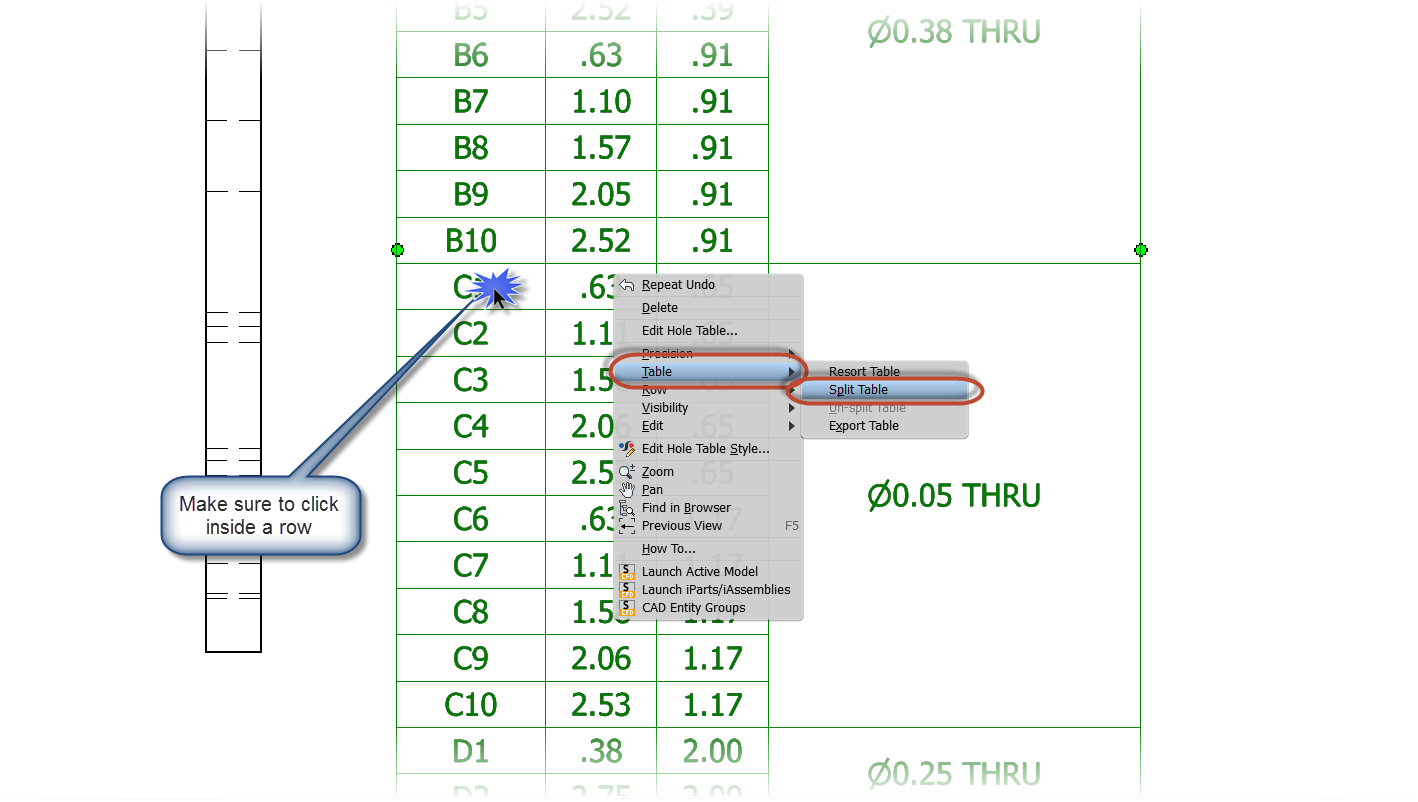 |
| Splitting the table. Make sure to click inside one of the fields |
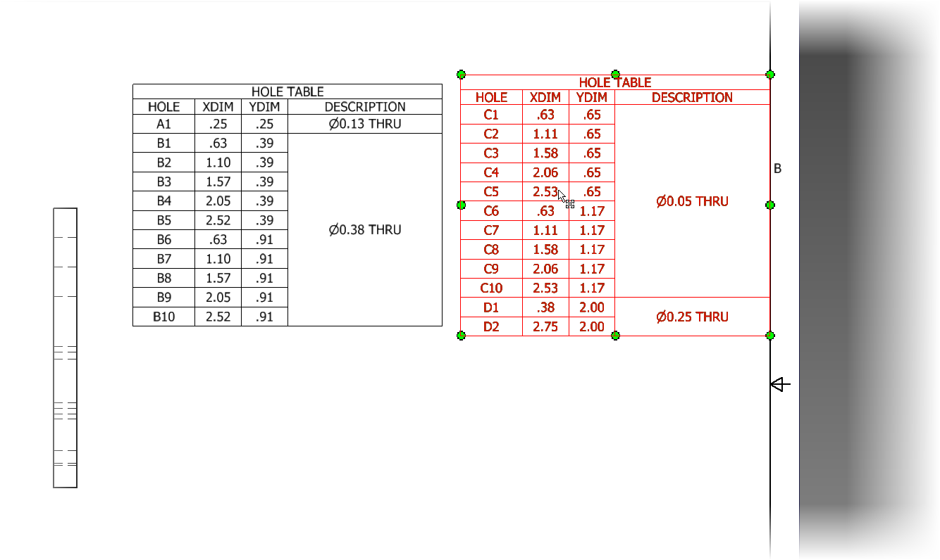 |
| Repositioning the newly split table. |
That's all there is to it! But there's a couple of other tips worth knowing.
1) If the table needs to be "recombined", right click on the table, and choose Table>Un-Split Table
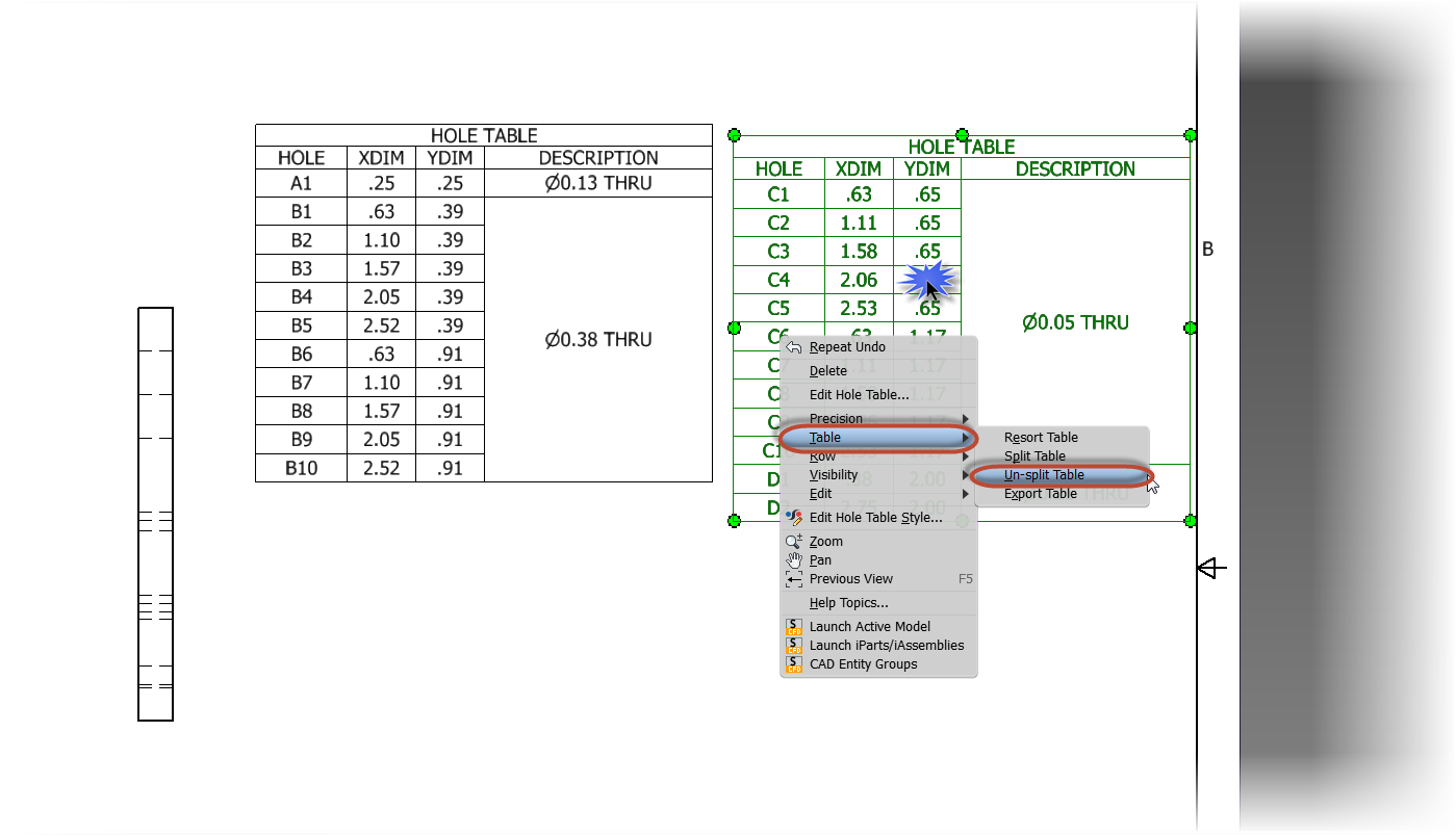 |
| Combining a "un-splitting" a split table. |
2) This is very important! Don't click on the border of the cell! The "Split Table" option will gray out if the border of the cell is clicked on!
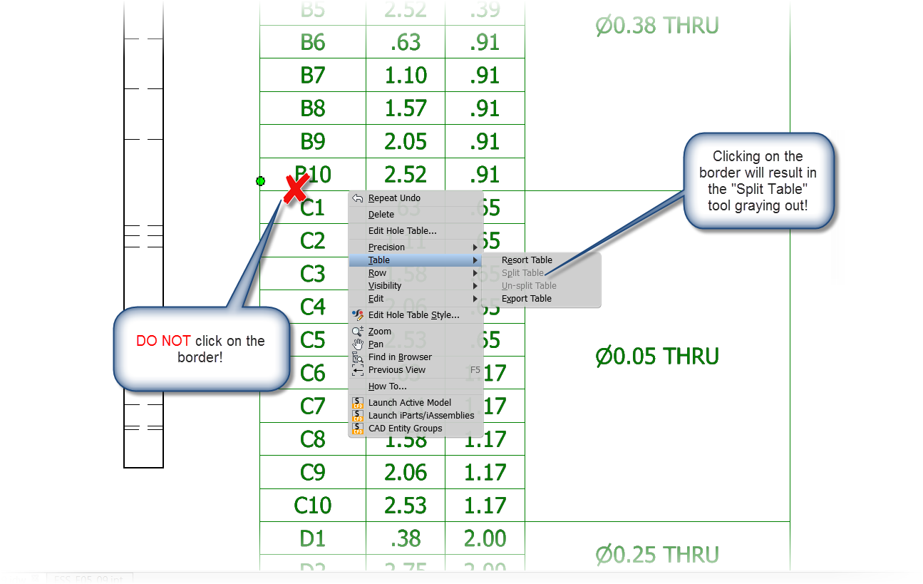 |
| This is what happens when clicking on the border of a cell! |
Have a few thoughts you want to share? Feel free to drop a comment or two!
Wednesday, December 26, 2012
A Holiday with Autodesk Force Effect Motion
"Never mistake motion for action.”
Ernest Hemingway
As the holidays approached, I found myself finally taking a look at something I had told myself to look at, and "never got around to it".
It was Autodesk's Force Effect Motion.
If you're not familiar with Force Effect Motion, it's a mobile app that works on Apple and Android devices, and allows for the laying out of mechanical mechanisms on a mobile device, instead of using paper and pencil, or even firing up a CAD package like Autodesk Inventor or AutoCAD.
So to satisfy my geeky curiosity, I imported two images to try out as backgrounds. The first was a picture of the landing gear for a Douglas DC-3, the second, the extended and retracted positions for a Boeing B-17 Flying Fortress.
I had a lot of fun playing with these two mechanisms. It allowed me to sit on my couch, and analyze the landing gear mechanisms and better understand how they worked!
I can see how using this application can help get a mechanism conceptualized before firing up a CAD application and creating models that may have to be thrown away because part way through the process, it's realized that I've gone down the wrong design road.
It's like creating a napkin sketch, but with the added benefits of being able to modify the diagram, and avoid getting food on your engineering designs!
In conclusion, I have to say I wish I had tried this app out sooner, but now that I have, I'm glad I did. The next time I'm at Planes of Fame, I'll definitely be getting a few more pictures of landing gear mechanisms to try out!
So here are a few videos. First, a video from the AutodeskMFG YouTube channel, showing how to use Force Effect Motion.
\
And next, the videos I created, showing the DC-3 and B-17 landing gear mechanisms. \
Ernest Hemingway
As the holidays approached, I found myself finally taking a look at something I had told myself to look at, and "never got around to it".
It was Autodesk's Force Effect Motion.
If you're not familiar with Force Effect Motion, it's a mobile app that works on Apple and Android devices, and allows for the laying out of mechanical mechanisms on a mobile device, instead of using paper and pencil, or even firing up a CAD package like Autodesk Inventor or AutoCAD.
 |
| A Force Effect Motion diagram - Courtesy of the Autodesk Force Effect Facebook Page. |
So to satisfy my geeky curiosity, I imported two images to try out as backgrounds. The first was a picture of the landing gear for a Douglas DC-3, the second, the extended and retracted positions for a Boeing B-17 Flying Fortress.
I had a lot of fun playing with these two mechanisms. It allowed me to sit on my couch, and analyze the landing gear mechanisms and better understand how they worked!
I can see how using this application can help get a mechanism conceptualized before firing up a CAD application and creating models that may have to be thrown away because part way through the process, it's realized that I've gone down the wrong design road.
It's like creating a napkin sketch, but with the added benefits of being able to modify the diagram, and avoid getting food on your engineering designs!
In conclusion, I have to say I wish I had tried this app out sooner, but now that I have, I'm glad I did. The next time I'm at Planes of Fame, I'll definitely be getting a few more pictures of landing gear mechanisms to try out!
So here are a few videos. First, a video from the AutodeskMFG YouTube channel, showing how to use Force Effect Motion.
\
And next, the videos I created, showing the DC-3 and B-17 landing gear mechanisms. \
Monday, December 24, 2012
Happy Holidays from Inventor Tales.
“A good holiday is one spent among people whose notions of time are vaguer than yours.”
John B. Priestly
It's Christmas Eve today, so I'm taking a break from a post this week.
This weekend has been a wonderful snowboarding holiday with friends in Mammoth, followed by Christmas with the family.
So it's time for a few days off of tech stuff.
Happy Holidays to everyone out there! Enjoy your Holiday!
~Jon Landeros
John B. Priestly
It's Christmas Eve today, so I'm taking a break from a post this week.
This weekend has been a wonderful snowboarding holiday with friends in Mammoth, followed by Christmas with the family.
 |
| A gorgeous view off of Chair 5 at Mammoth |
So it's time for a few days off of tech stuff.
Happy Holidays to everyone out there! Enjoy your Holiday!
~Jon Landeros
Sunday, December 16, 2012
Matching Colors in Autodesk Showcase
“Don't miss all the beautiful colors of the rainbow looking for that pot of gold.”
Unknown
If you want to know how important getting the proper color of a logo can be. Get it wrong and see how quickly the Marketing Department comes looking for you.
The truth is it can be very important. For things such as color schemes and logos, it can be critical. Company "red" is not just "red". It's a specific red, or blue, or yellow.
When working in Autodesk Showcase, there have been a few times where I've needed to use a specific color. And if it really is that important, I'll ask for the RGB (Red, Green, Blue) values of the color.
Many times, the Marketing Department has those values, and can provide them for you.
But I recently I ran into a case where I needed to match the color of a logo as closely as possible, and and I didn't have the RGB values to work with. So what did I do?
I could have played with the color until I matched it by eye, but that can be time consuming to do, and I wanted to get as close as I could, as quickly as I could.
Fortunately, when editing a color, showcase has an "eye dropper" icon that lets you select and existing object, and "paint" it with that color.
I was able to use it to select the object I needed to match the logo with the eyedropper, and "paint" the object with that color. It worked like a charm!
Of course this isn't as accurate as having the RGB values. But when I couldn't get the RGB values, this was more than adequate to get me what I needed! It also saved me a huge amount of time because now I didn't have to finesse the color into play.
So for that, Here's a quick video on how I used this nice little trick
Unknown
If you want to know how important getting the proper color of a logo can be. Get it wrong and see how quickly the Marketing Department comes looking for you.
The truth is it can be very important. For things such as color schemes and logos, it can be critical. Company "red" is not just "red". It's a specific red, or blue, or yellow.
| The KETIV logo. It's not just "red". It's got a specific RGB value. |
When working in Autodesk Showcase, there have been a few times where I've needed to use a specific color. And if it really is that important, I'll ask for the RGB (Red, Green, Blue) values of the color.
Many times, the Marketing Department has those values, and can provide them for you.
But I recently I ran into a case where I needed to match the color of a logo as closely as possible, and and I didn't have the RGB values to work with. So what did I do?
I could have played with the color until I matched it by eye, but that can be time consuming to do, and I wanted to get as close as I could, as quickly as I could.
Fortunately, when editing a color, showcase has an "eye dropper" icon that lets you select and existing object, and "paint" it with that color.
 |
| Edit the color by right clicking on it, and choose the eyedropper |
Of course this isn't as accurate as having the RGB values. But when I couldn't get the RGB values, this was more than adequate to get me what I needed! It also saved me a huge amount of time because now I didn't have to finesse the color into play.
So for that, Here's a quick video on how I used this nice little trick
Tuesday, December 11, 2012
A Couple of Success (and Hopefully Inspirational) Videos
“Have great hopes and dare to go all out for them. Have great dreams and dare to live them. Have tremendous expectations and believe in them.”
Norman Vincent Peale
Technology marches a long at a staggering pace. As a matter of fact, I'm not even sure it's marching. It's sprinting like a jackrabbit hopped up on Red Bull.
Is it stressful? Sure! Trying to keep up with all this change isn't easy.
Is it difficult? It can be. Knowing what to implement is as tricky as knowing what's available to you!
But is it amazing to see how technology is changing things? Yes it is! It's exciting to see the evolution, and even revolution, in technology.
To that end, I'm sharing a some videos that I hope offer some inspiration.
The first is from the General Session at Autodesk University 2012, where the CEO of Autodesk, Carl Bass talks about "What if?" and how technology, particularly Autodesk technology, is fueling the answers to that question. (Thank you CADRelations for the video)
And to show a company that came up with creative answers to "What if?" Here's a story on GK Machine is using Autodesk products to improve their products and processes.
But how about this story of using technology to answer the "What if?" question, as cool as it would be to say it is. The video and story are worth checking out. It's about a group of five high school kids built a flight simulator for a Colonial Viper from Battlestar Galactica! Autodesk Inventor played it's part as the tool that enabled it, but imagine where these kids are going with technology!
First. Here's the Gizmodo story on how they got started!
How cool is that!
Norman Vincent Peale
Technology marches a long at a staggering pace. As a matter of fact, I'm not even sure it's marching. It's sprinting like a jackrabbit hopped up on Red Bull.
Is it stressful? Sure! Trying to keep up with all this change isn't easy.
Is it difficult? It can be. Knowing what to implement is as tricky as knowing what's available to you!
But is it amazing to see how technology is changing things? Yes it is! It's exciting to see the evolution, and even revolution, in technology.
To that end, I'm sharing a some videos that I hope offer some inspiration.
The first is from the General Session at Autodesk University 2012, where the CEO of Autodesk, Carl Bass talks about "What if?" and how technology, particularly Autodesk technology, is fueling the answers to that question. (Thank you CADRelations for the video)
And to show a company that came up with creative answers to "What if?" Here's a story on GK Machine is using Autodesk products to improve their products and processes.
But how about this story of using technology to answer the "What if?" question, as cool as it would be to say it is. The video and story are worth checking out. It's about a group of five high school kids built a flight simulator for a Colonial Viper from Battlestar Galactica! Autodesk Inventor played it's part as the tool that enabled it, but imagine where these kids are going with technology!
First. Here's the Gizmodo story on how they got started!
But they followed through with it, and got it done!
Here's the completed nearly product and accompanying story from Gizmodo!
***Edit 11-Dec-2011***
I found the link to the "The Viper" Webpage!. Check out their team site here!
***End edit****
***Edit 11-Dec-2011***
I found the link to the "The Viper" Webpage!. Check out their team site here!
***End edit****
How cool is that!
Sunday, December 09, 2012
A Quick Tip on Positioning Section Lines in Autodesk Inventor
“I went to a bookstore and asked the saleswoman, "Where's the self-help section?" She said if she told me, it would defeat the purpose”
George Carlin
Creating section views with Autodesk Inventor. It's not a difficult thing. But there is a trick I sometimes use that I think is worth sharing on how to position the section line.
The most common way, is to choose one of the projected construction elements. This will grab things like the center or quadrant of a circle, a midpoint of a line, or a vertex where two lines meet. This probably covers nearly all cases of what most users need to do.
But what if there's a case where a section line needs to be placed a certain distance from the edge, and no convenient point exists?
First, place a section line on the view, but don't let it constrain to anything. I like to place the section line completely off the view geometry to make good and sure I don't pick a point by mistake.
Now with the view placed (it looks like a projected view right now), right click on the section line, and choose "Edit".
'
Now the sketch the section line lives on becomes active, and it can be positioned using constraints and dimensions, just like any sketch. One important thing to note. Make sure to use the "Project Geometry" tool to project geometry off the view. Otherwise it can't be picked.
Once the geometry is projected, it can be constrained and dimensioned like any sketch!
Do you have a place this might be helpful! Drop a comment!
And naturally, here is the accompanying video!
George Carlin
Creating section views with Autodesk Inventor. It's not a difficult thing. But there is a trick I sometimes use that I think is worth sharing on how to position the section line.
The most common way, is to choose one of the projected construction elements. This will grab things like the center or quadrant of a circle, a midpoint of a line, or a vertex where two lines meet. This probably covers nearly all cases of what most users need to do.
 |
| The construction element |
But what if there's a case where a section line needs to be placed a certain distance from the edge, and no convenient point exists?
First, place a section line on the view, but don't let it constrain to anything. I like to place the section line completely off the view geometry to make good and sure I don't pick a point by mistake.
 |
| Placing the section line "off the geometry". |
Now with the view placed (it looks like a projected view right now), right click on the section line, and choose "Edit".
'
 |
| The section view completed off the geometry |
 |
| Now to edit the placed view |
Now the sketch the section line lives on becomes active, and it can be positioned using constraints and dimensions, just like any sketch. One important thing to note. Make sure to use the "Project Geometry" tool to project geometry off the view. Otherwise it can't be picked.
 |
| Use project, constrain, and dimension to position the section line. |
Once the geometry is projected, it can be constrained and dimensioned like any sketch!
 |
| The completed section view |
Do you have a place this might be helpful! Drop a comment!
And naturally, here is the accompanying video!
Friday, December 07, 2012
Autodesk Vault 2013 and Microsoft .Net 4.5 - Not Cool Together
“Never, never, never, never, never! Pray you, undo this button.”
William Shakespeare
Earlier this week, after attending Autodesk University 2012, I decided to install Visual Studio Express, so I could go ahead and try my hand at the Autodesk Inventor API.
The download went fine, and soon I was installing away.
As the progress bar cruised along, I noticed one message, "Installing Microsoft .NET Framework 4.5".
I wonder if that's a good idea? I thought. But I dismissed it. I was going to lunch, and my mind was elsewhere. Like food.
When I returned to the office. Visual Studio was merrily installed. All was good in the Kingdom of Laptop.
I wasn't going to be able to work with Visual Studio, so I moved on and worked on other projects.
Eventually, that other project led me to look for some files out of my installation of Autodesk Vault 2013.
I open up the folder where I know the files are, and......... Nothing. No files appear. NOTHING!
Imagine the camera panning away from me as I scream: "NOOOOOOO!"
I have that sinking feeling. Did the files get deleted? This my personal Vault. Nobody else accesses it. And I didn't delete them.
On a hunch, I change from Detail to Icon view. My files appear! They're still there!

But why won't they show in the Detail View?
Suddenly I remember. .NET Framework 4.5..... The tingle in the back of my neck was trying to tell me something. I remember it's not a good idea to install it with Vault!
All is NOT well in the Kingdom of Laptop.
Fortunately, I had a restore point and was able to "hit the eject button" and return to a state before Visual Studio.
Needless to say, if you're running Autodesk Vault 2013. Stay away from .Microsoft .NET 4.5.
I don't know that .NET 4.5 is bad. As a matter of fact I doubt it. All I know is that it doesn't play well with Autodesk Vault 2013. I wouldn't expect it's going to play well with earlier versions either.
So until Vault supports .NET 4.5, stay safe, stay away.
Don't do what I did!
****EDIT 2-August-2013 ****
I'm a bit late in updating this, I'm afraid it slipped by me. But Service Pack 1 for Autodesk Vault 2013 addes support for .Net 4.5! So if you're seeing this issue, make sure Service Pack 1 is installed.
It a can be downloaded at the link here!
William Shakespeare
Earlier this week, after attending Autodesk University 2012, I decided to install Visual Studio Express, so I could go ahead and try my hand at the Autodesk Inventor API.
The download went fine, and soon I was installing away.
As the progress bar cruised along, I noticed one message, "Installing Microsoft .NET Framework 4.5".
I wonder if that's a good idea? I thought. But I dismissed it. I was going to lunch, and my mind was elsewhere. Like food.
When I returned to the office. Visual Studio was merrily installed. All was good in the Kingdom of Laptop.
I wasn't going to be able to work with Visual Studio, so I moved on and worked on other projects.
Eventually, that other project led me to look for some files out of my installation of Autodesk Vault 2013.
 |
| These are my files, as last left. |
Imagine the camera panning away from me as I scream: "NOOOOOOO!"
 |
| Now all I see is this! |
I have that sinking feeling. Did the files get deleted? This my personal Vault. Nobody else accesses it. And I didn't delete them.
On a hunch, I change from Detail to Icon view. My files appear! They're still there!
But why won't they show in the Detail View?
Suddenly I remember. .NET Framework 4.5..... The tingle in the back of my neck was trying to tell me something. I remember it's not a good idea to install it with Vault!
All is NOT well in the Kingdom of Laptop.
Fortunately, I had a restore point and was able to "hit the eject button" and return to a state before Visual Studio.
Needless to say, if you're running Autodesk Vault 2013. Stay away from .Microsoft .NET 4.5.
I don't know that .NET 4.5 is bad. As a matter of fact I doubt it. All I know is that it doesn't play well with Autodesk Vault 2013. I wouldn't expect it's going to play well with earlier versions either.
So until Vault supports .NET 4.5, stay safe, stay away.
Don't do what I did!
****EDIT 2-August-2013 ****
I'm a bit late in updating this, I'm afraid it slipped by me. But Service Pack 1 for Autodesk Vault 2013 addes support for .Net 4.5! So if you're seeing this issue, make sure Service Pack 1 is installed.
It a can be downloaded at the link here!
Tuesday, December 04, 2012
Wrapping up a Little Fun - Modeling the Six Sided Die
"It means that I, like God, do not play with dice and do not believe in coincidence."
"V" From V for Vendetta
Afrer modeling nearly all of the gaming dice, (20 sided, 12 sided, 10 sided, 8 sided, and 4 sided), I decided to complete the set with the 6 sided.
Originally, I was going to post this particular die as a bit of a joke. Draw a square, extrude it into a cube, break the edges and slap some numbers on it. How hard could it be?
Could you believe I found a way to complicate it? And find a use for a new trick in the process?
I'll share the trick at the end of the blog. First, I'll start out with the steps I used. Which let's face it, aren't that difficult. But there might still be a trick or two to use.
1) First, I created the cube. Since I used Autodesk Inventor 2013, I used the "Box" primitive that was added in this release.
2) Next, I added fillets to break the sharp edges. I used the "All Rounds" option to get every edge.
3) Finally, I added the numbers to each side of the die.
And that's it. The die is finished.
But there's an epilogue to this exercise. Looking at the die, I didn't like the way it looked. The edges were too crisp and clean. It didn't look like a real die would. I decided I wanted the vertices of the die to look more rounded than the rest of the die.
So how did I go about changing that? I edited the fillet, created in step 2, and on the "setbacks" tab, I chose each corner of the die, and changed the setback until I liked the result (I used .1875 in my case).
I found it gave a much more eye pleasing result than the tight corners I initially had.
Ironically, I can't think of another time I've really used the setback setting. It's possible that I might have used it somehwhere, but I can't recall one.
I guess it just goes to show that one should never say "I'll never use that tool!"
And naturally, I have to add a rendering from Autodesk Showcase, just because!
And if you want do download the model here you go!
Click here to download from Autodesk 360 (no login required)
Click here to download from GrabCAD (login required)
I hope you find this model an interesting diversion!
"V" From V for Vendetta
Afrer modeling nearly all of the gaming dice, (20 sided, 12 sided, 10 sided, 8 sided, and 4 sided), I decided to complete the set with the 6 sided.
Originally, I was going to post this particular die as a bit of a joke. Draw a square, extrude it into a cube, break the edges and slap some numbers on it. How hard could it be?
 |
| Examples of 6 sided die (courtesy Wikipedia) |
Could you believe I found a way to complicate it? And find a use for a new trick in the process?
I'll share the trick at the end of the blog. First, I'll start out with the steps I used. Which let's face it, aren't that difficult. But there might still be a trick or two to use.
1) First, I created the cube. Since I used Autodesk Inventor 2013, I used the "Box" primitive that was added in this release.
 | |
| Using the "Box" primitive to create the cube for the die. |
2) Next, I added fillets to break the sharp edges. I used the "All Rounds" option to get every edge.
 |
| Adding fillets to break the edges |
3) Finally, I added the numbers to each side of the die.
 |
| Finally, adding the numbers! |
And that's it. The die is finished.
But there's an epilogue to this exercise. Looking at the die, I didn't like the way it looked. The edges were too crisp and clean. It didn't look like a real die would. I decided I wanted the vertices of the die to look more rounded than the rest of the die.
 |
| Looking carefully the rounded corners can be seen (image courtesy Wikpedia) |
 |
| Thg "too crisp" corner shown. I'm using the "shaded with edges" setting to show the corner more clearly. |
So how did I go about changing that? I edited the fillet, created in step 2, and on the "setbacks" tab, I chose each corner of the die, and changed the setback until I liked the result (I used .1875 in my case).
I found it gave a much more eye pleasing result than the tight corners I initially had.
 |
| Changing the setback |
 |
| The completed die with setback |
I guess it just goes to show that one should never say "I'll never use that tool!"
And naturally, I have to add a rendering from Autodesk Showcase, just because!
 |
| And one for the show! |
And if you want do download the model here you go!
Click here to download from Autodesk 360 (no login required)
Click here to download from GrabCAD (login required)
I hope you find this model an interesting diversion!
Sunday, December 02, 2012
Creating Arcs without Exiting the Line Tool in Autodesk Inventor
“Force never moves in a straight line, but always in a curve vast as the universe, and therefore eventually returns whence it issued forth, but upon a higher arc, for the universe has progressed since it started.”
Proverb
Autodesk University 2012 is over! And frankly, it was fantastic! I had a great time, met some wonderful people, and learned a ton of new things!
But a consequence of getting all that information is.... I'm beat! So as I play catchup on sleep, and life, this blog post remains quite brief.
Has anyone out in the verse, while sketching, tried to create an arc from a line in Autodesk Inventor? It can be done by using the "arc" tool, but it's going to likely remain returning to the sketch, and adding sketch constraints.
This tip comes from the "bucket of little things" that are simple, but make sketching easier. This is how to create a tangent, or perpendicular arc without exiting the line tool.
1) Start drawing the lines required for the sketch
2) Stay in the line tool when ready to create the arc.
3) Click on the start of the arc, and while holding the left mouse button down (this is important!), imaging drawing the arc with a pencil. Make sure to hold the left mouse button down until ready to create the arc.
4) Draw the arc (either perpendicular or tangent) while holding the left mouse button down. When ready, lift the left mouse button. Now you have created an arc!
Granted, there is a trick to it, and it takes practice. The single biggest tip I can offer is to draw a little more slowly, and definitely more deliberately! Rushing the task usually means making mistakes and redoing things.
But with a little practice, I think this is a great tool. I encourage giving it a try!
For a little added info, here's a video to go with it.
Proverb
Autodesk University 2012 is over! And frankly, it was fantastic! I had a great time, met some wonderful people, and learned a ton of new things!
But a consequence of getting all that information is.... I'm beat! So as I play catchup on sleep, and life, this blog post remains quite brief.
Has anyone out in the verse, while sketching, tried to create an arc from a line in Autodesk Inventor? It can be done by using the "arc" tool, but it's going to likely remain returning to the sketch, and adding sketch constraints.
This tip comes from the "bucket of little things" that are simple, but make sketching easier. This is how to create a tangent, or perpendicular arc without exiting the line tool.
1) Start drawing the lines required for the sketch
 |
| Start with the line tool. |
2) Stay in the line tool when ready to create the arc.
 |
| Don't exit, stay in the line tool! |
3) Click on the start of the arc, and while holding the left mouse button down (this is important!), imaging drawing the arc with a pencil. Make sure to hold the left mouse button down until ready to create the arc.
 |
| Getting ready to create the arc |
4) Draw the arc (either perpendicular or tangent) while holding the left mouse button down. When ready, lift the left mouse button. Now you have created an arc!
 |
| When ready to create the arc, lift the left mouse button. |
Granted, there is a trick to it, and it takes practice. The single biggest tip I can offer is to draw a little more slowly, and definitely more deliberately! Rushing the task usually means making mistakes and redoing things.
But with a little practice, I think this is a great tool. I encourage giving it a try!
For a little added info, here's a video to go with it.
Do you have a few thoughts or suggestions? Add a comment below!
Subscribe to:
Posts (Atom)