Find us on Google+ 2017 ~ Inventor Tales

Sunday, December 24, 2017

A Quick Post for the Holidays! - Improvising a Hole Gauge

It's been busy for me getting ready for the holidays, but I did have one little tip when your practicing the future of making things.

I found myself needing to double check a hole size.  All I needed to do was to check to see if I #6, or a #8 screw would fit in a hole in a simple bracket.

Normally, I would check it with calipers.  I'm used to being able to do that.  I almost always have them available.  Almost...

Dial Calipers, similar to my set.  These are perfect for measuring small holes,
but not when you don't have them with you!
Image Credit: Wikipedia
But today, I didn't have calipers my calipers.  They were at home, and I wasn't.  So what to do? 

I realized what I did have, was a full drill index (fractional, letter, and number drills!).  In other words, a full set of improvised hole gages!

My set of hole gages!  They can also be used to drill holes! 
I just placed a few drills in the hole I was checking until I got one that told me what I needed to know.  The hole was too small for a #8 screw.  I had to get some #6 screws to do the job. 

It's not a perfect fit, but it's enough to tell me only a #6 screw will fit.
A #8 is too big. 
So as your working in your own shop, remember that while you may not have the perfect tool for the job, with a little improvisation, you may have a perfectly acceptable substitute! 

Sunday, December 10, 2017

Lessons from the Real World - The Folly of Ignoring the 7Ps

There's an old saying about the "7 Ps".  To put it bluntly, the 7 Ps are: " Proper, Prior, Planning, Prevents, Piss, Poor, Performance".  I remember my Father mention mentioning it in reference to his old U.S. Navy days.

But last week, I made the mistake of ignoring the "7 Ps".  I allowed myself to fall victim to the perfect storm of laziness and complacency.  The true frustration of the situation was that I was left with nobody to blame but myself. 

Unfortunately, there's no pony to blame this time.
It was simply: My. Own. Damn. Fault.

It started with my girlfriend's car due for an oil change.  It's automotive maintenance that I've done for about 30 years.  I can do it in my sleep.  Which introduces the first demon to the equation.  Complacency.

I had the oil, I had the filter, all I had to do was get my girlfriend to leave me her car so I could change the oil.  I can do it in about 20-30 minutes, and that's taking my time to make sure I do it right.

No problem, right?  Well, remember that demon of complacency I welcomed into my world?

My girlfriend takes my truck to work so I can work on her car, easy money, as they say.  So I grab  the oil, and grab a few tools out of my toolbox, and get started.

Sure, I grab the drain pan, and the required tools, I have the oil drained in no time.  Then I realize I left the oil in the house, so I go inside to get that.  While I'm at it , I grab a few extra paper towels, I don't have enough in the garage.

The second demon of laziness has joined the party, I was too lazy to gather up everything I needed ahead of time.

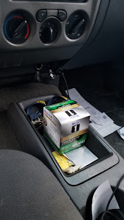
The oil filter, safe on the center
console of my truck
So I move on and remove the oil filter, and realize I need to go the the oil filter too.

And that's when it dawns on me, the oil filter is in the truck.  The truck that my girlfriend took to work!

So with the oil now drained out of my girlfriend's car, I ended up taking a lovely stroll to the nearby parts store to purchase another filter.   It was on that stroll through my fine town that I was able to contemplate my mistake.

Thankfully, it wasn't long before I had completed the job.  I had to take a moment to sit down and have a laugh at my own expense. 

So what was the lesson, and the point of writing this out?  What did I learn on my Hobbit like unexpected journey to the parts store?

I realized that I had become so intent on executing my plan, I didn't actually have a plan.  It was really more of a goal of changing oil, with the execution limited to "I'm going to do some "mechanic" stuff!" in the middle.

Normally, I lay everything out before I get started, should it be a tool, a filter, or fresh oil, it's right there when I needed it.

But this time, I broke that routine.  I still had oil in the house, not all the paper towels I needed, and fatefully, the filter in a car that wasn't there.  I found myself making extra trips to get supplies that I didn't have laid out.

Had I laid everything out like I normally do, I would have realized I didn't have the filter and could have easily fixed the problem before getting started.

But I didn't, I started before I had everything laid out, and paid the price.

I think that happens to many of us in our endeavors.  We want to see action and measurable progress, so we jump to the execution stage, neglecting the planning, or "laying out your tools and supplies".

And we end up seeing action alright!  We end up acting, and then we end up reacting as we redo our efforts and end up having to adapt to challenges that a little extra planning may have foreseen.  We "take that walk to the parts store".

I'll be sure not to let this mistake be made in vain.  The next oil change, I'll have everything right where I need it, like I have in the past.  It will be a final "sanity check" to make sure I'm truly ready to execute.

And I'll be taking that lessons to other projects in my life, making sure to put the extra effort into minding those "7Ps" next time!

Please learn from my mistake, don't fall into the trap I fell into!


Don't confuse action with progress!

Wednesday, December 06, 2017

Lesson's From LIfe's Workbench - Working with Helical Inserts

Ahh. The helical insert.   If you've run into a mangled thread, there's a good chance you've had to use one.  Most likely it's come in the form of a tightly wound, diamond shaped wire which forms the insert.

The common helical-insert.
By The original uploader was Boellhoff at German Wikipedia - Transferred from de.wikipedia to Commons by MichaelFrey using CommonsHelper., Attribution, https://commons.wikimedia.org/w/index.php?curid=7363606


You may also know them as "Heli-Coil" inserts.  Heli-Coil is actually the name of a specific brand of helical inserts, but the names have become interchangeable, much like Teflon (PTFE), Kleelex (facial tissue), and Inconel 718 (Nickel 718).

Many of us have used them to repair stripped threads, they can also be used in softer materials, such as aluminum, to create a more durable thread.

A helical- insert used to repair a thread.
But like any fastener, they need to be placed into a threaded hole, which requires drills to tap holes, and depths for threads

Luckily, I found a great website that has the recommended taps, and hole diameters for helical inserts.

Our friends at Noble Aerospace have provided a recommended drill size chart, and a tap chart for both Imperial and Metric threads.

It's a nice resource if you're using helical inserts in your next design!

How Noble of them indeed! 

Additional photo credits:

photo credit: rustyheaps Repairing exhaust manifold, XK engine via photopin (license)

Monday, December 04, 2017

A 3D "Doodle" with Simulation in Fusion 360

A few days ago, an experienced engineer was explaining to us how changing the geometry of a component could affect the loads that it could have on how a part could handle the forces placed upon it.


Where the conversation started.
The representation of the mounting foot.

He explained that adding ribs to a mounting foot could greatly change how the mounting foot absorbed the loads, making for a more durable part. 

The modified part with ribs encompassing
the mounting hole.
So on this night I decided to build two parts pictured above,  and applied the same load of 1500 psi to them using Fusion 360.  I thought it would be a good exercise, and an opportunity to validate what I had learned.

The hole diameters and positions are the same, as well as the face bearing the load. 

After fixing the parts in the same place, I ran a simulation to see what would happen.

And the results of these quick tests was pretty interesting!

The ribbed foot had a much higher safety factor than the non-ribbed part.

The two parts next to each other.
The difference 
It was a nice exercise and validation of a concept.  And it was nice to have Fusion 360's simulation capabilities to be able to quickly test out an idea and quantify it.

Best part is now I have these parts for reference later!

It's just like a 3D note!

And finally, if you'd like to download the parts I created, you can find them here and here!

Wednesday, November 29, 2017

Lessons From Life's Workbench - The Blind Rivet

Over the last few weeks, I've mentioned how solid rivets are sized by part number and selected for diameter and length.

Solid rivets joining two pieces of
aluminum together. 
Solid rivets are amazing little pieces of metal.  They've been used in aircraft for decades, and if you've flown on an airplane, the odds are you've been depending on these little pieces of metal to ensure your safe flight.

And while these pieces are amazing in both their simplicity and effectiveness, like anything, they are not without their drawbacks.

They're inexpensive, but they require a certain amount of skill to properly set.  Proper riveting takes practice, and I found if I don't do it for a while, I have to shoot a few practice rivets to get "back into the groove." 

The other problem is access to both sides of the part are required.  The rivet has to be "shot" with a tool from one side of the part, and "bucked" or set, from the other.

If you're curious about seeing how solid rivets are set, the Experimental Aircraft Association has a great video explaining that here!

Moreso, it's likely that one person won't be able to reach both sides of the parts to be joined.  That means that two people are needed to set the rivet, a "bucker" and a "shooter".

Two workers setting solid rivets.
If you take a couple of moments to think about that, what you have is a rivet that maybe inexpensive, the workers required to place will be where the expenses will be found.

The blind rivet, also known as a "pop" rivet or "Cherry-Max" rivet solves both of these issues.  'For trivia's sake, the name "Cherry-Max" is derived from Cherry Aerospace, a prominent maker of  blind fasteners.

These rivets have a metal stem (mandrel) that is drawn through the rivet by a special tool.  The metal stem expands the rivet as it's pulled expanding the rivet and setting it in place.  The stem breaks off inside the rivet, adding to the rivets strength.

A blind rivet diagram.  Image from FAA Advisory Circular
AC43.13-1Bhttps://www.faa.gov/documentLibrary/media/Advisory_Circular/AC43.13-1b.pdf


The advantage of these rivets is they don't require the skill that a solid rivet requires. They also don't require that the part be accessible from both sides.   The drawback of these rivets is they are much more expensive than their solid counterparts.

A blind rivet tool, with unset blind rivets under the
"Design Differently" sticker on my laptop.
So like in so many cases in design and manufacturing, a benefit isn't seen without making a concession somewhere else.  So when all is said and done, you can still find both types of rivets in widespread use.

If you're curious about how to set blind rivets, here's a link to a great video here.

For more information on selecting blind rivets, check out the process guide  provided by Cherry Aerospace at the link here.

I  leave it to them to provide the info for you!   Mostly because I have to review it myself to refresh in my own memory!

But there you have a few of the "wheres and whys" of rivets.  I hope the info I've compiled here helps you out!

Photo Acknowledgements:

photo credit: The Library of Congress Riveting team working on the cockpit shell of a B-25 [i.e. C-47] bomber at the plant of North American Aviation, Inc., Inglewood [i.e. Douglas Aircraft Company, Long Beach], Calif.   (LOC) via photopin (license)

Sunday, November 26, 2017

A Quick Tip on Creating a New Drawing in Fusion 360

The Thanksgiving Holiday here in the United States and some studying for a class have been keeping me busy, but I've been starting to get a little seat time creating drawings in Fusion 360 for a wooden rack I've been working on.  
The Fabric Rack in it's current state.
There's still some adjusting to be done! 
The tip I'll share is a simple one, but one that not everyone may realize is there.  

I know I haven't been using this tool nearly as much as I should have! 

If you right click on a component in the model tree, you can create a drawing for that component by choosing Create Drawing

Creating a drawing from the model.


Choosing that option, a dialog box appears that gives the following options. 

1. Create a drawing of the full assembly found in the model, or just selected components in the model. 
The first step to creating a drawing

2. Create a new drawing from the selected component(s), or add a component to an existing drawing. 

3. Choose a template drawing or start from scratch. 

4. Choose to use the ASME or ISO drawing standard.

5. Choose the default units for the drawing.

6. And finally, choose the sheet size for the drawing.  

Once you hit OK, the drawing will generate and you'll the opportunity to place the views on the darwing.  These options include

1. View Orientation

2. View Style, such as Visible Edges, Visible and Hidden Edges, Shaded, or Shaded with Hidden Edges.

3. Scale so you can size the view to the page.

4. Tangent Style, which include Full Length, Foreshortened, and Off. 

5. Toggle Interference Edges on or off. 

6. Toggle thread display on or off.

I found it can be a slick way of creating a view, some of which I'm still testing out!  But I think it's well worth taking a deeper look!  

I'll keep you posted! 


Thursday, November 23, 2017

Lessons from Life's Workbench - Penetrant Inspection

Happy Thanksgiving to those in the United States.  Enjoy the holiday!  Here's a quick post on penetrant inspection for your consideration! 

In my aircraft maintenance classes, I've been able to try my hand at dye penetrant inspection.  
An example of cracks in a part.  This is actually from
magnetic particle inspection test.  But the tests are similar,
and it's the best picture I have! 

There are a few variations of the process, but the one I performed soaked the part in an light oil containing a phosphorescent dye.  

The dye soaks into cracks and voids in the material.  After soaking, the part is rinsed to remove penetrant on the surface of the part, and finally, it's sprayed with a powder like developer to draw some of the remaining penetrant out of the flaws so they can be seen with a UV light.  

After inspection, the part is thoroughly cleaned and returned to service, assuming it passed inspection of course.  

It's a quick, fairly easy to perform test, and can be a great to find surface flaws on a part.  

It's also messy, at least where I learned how to do it!  But a little mess never hurt anyone. 

But my experience, isn't vast by any means.  It's something I've tried enough to gain some familiarity with.  

For a little more information, check out these resources.  


Wednesday, November 15, 2017

Lessons From Life's Workbench - Intergranular Corrosion

One of the most insidious types of corrosion I learned about in my classes is intergranular corrosion.  Aluminum alloys containing copper, such as 2024 aluminum, particularly if it's been improperly heat treated.  

The copper in the alloy comes out of the solution, and creates tiny galvanic cells that begin corroding the metal. 

The sneaky part of this type of corrosion is that it can happen deep inside the material, and may not become visible until the corrosion breaks the surface of the material in a process called exfoliation. 

 
Here are some pictures of aluminum that has some serious exfoliation.
The metal has completely disintegrated.
Another angle of the same extrusion.
You can see how the material has flaked away.
It goes without saying that intergranular corrosion is bad.  But if it can start in the interior of a material, where it can't be seen,, how can it be found?

That's where nondestructive tests (NDT) such as ultrasonic inspection or eddy current inspection can be employed to locate and eliminate this type of corrosion before it affects the strength of the structure. 

That's it for this weeks tip!  Have a great week! 


Monday, November 13, 2017

Using Your Resources to Design in Fusion 360

I've had a mental idea to build a simple rack to hold bolts of fabric in Fusion 360. 

It would look similar to this mobile pipe rack found on the McMaster Carr Website

But naturally, the store bought version doesn't quite meet my needs.  Murphy's Law wouldn't allow that!  So that leaves me in the position of designing and building one. 

Here's one side of the rack, mostly done,

And seeing how I don't want to work on it evening upon evening, that means I have to take advantage of every step I can to increase the efficiency my design time.

Now I should mention that many of these steps I've shared before, so this will be a link back to these posts.  But I think it's a good example of how these processes can come together and become greater than the sum of their parts. 

Here are the tips!

1) Don't Create a Model if You Don't Have to!

The rack needs to be mobile, so it needs to rest on casters.  Fortunately, Fusion 360 has a link to the McMaster Carr website that lets you insert models from their website into your design.  The part number is included, so you can always order the part from McMaster Car if you like.

Downloading these casters was more accurate and less time
consuming than trying to build my own versions

Here's the link to a previous post if you want to read more!

2) If you have to build it, reuse it! 


Every wooden piece pictured here was built and resized from
one source model.

The frame is going to be made primarily of 2x4s.  And while this isn't a complicated part, why keep drawing rectangles over and over again if you can just Copy and Paste New?  This tool allows you to copy a part, paste a new, independent version, then resize and reposition it where needed.

You can find a link to more details there. 

3) Don't rebuild what you don't have to! Redux!

I couldn't find the joist hangar on the McMaster Carr website.  It might be their, but I couldn't find it.  So instead I tried GrabCAD and found it here.

The joist hanger inserted into the model.


The download wasn't quite as slick as the one on the McMaster Carr website, but it was still a lot quicker than building the model myself. 

In Conclusion!

The design still has a long way to go.  It's not even complete, and I can already see a few changes I'll probably want to make.  But being able to reuse and download parts got me a lot further down the road in a couple of hours than I otherwise would have been.

So I hope these ideas inspire you to try a few things, and get a little further down the road yourself!

Friday, November 10, 2017

A Life Lesson - My Inspiration from a Little Black Cat

Foreword

This post is far off my usual topics.  It's a reflection on a little inspiration coming from the strangest places.

But who doesn't need that once in a while!

*******

This week has been one of those weeks.  You've probably had them, where nothing seems to go right.

In work and play, I've had projects go sideways, problems big and small plague me.  Like zombies from the grave, rookie mistakes I made months, or even years ago came back to bite me.

It was one of those weeks that leaves you asking yourself "Why am I doing this?"  (Looks at bank statement).  "Oh yeah, that's why.'

But even in this week of frustration, a ray of inspiration came to me.  And strangely enough, that inspiration came in a form I would have never expected.

A couple of nights ago I saw two of my cats, who are brothers and littermates, get into a little playful "rough and tumble". It's not uncommon, they like to roughhouse with each other.

The contenders were...

"Runtley" earned his name because he's the runt of the litter, he was born a little guy, and now, fully grown, he's small and slight of build.

This is "Runtley the Runtling"
His brother, "Scar", earned his name because he was missing a chunk of fur under his eye when we adopted him, a product of an unknown kitten misadventure. The wound has since healed, but the name remains. Scar is bigger, bolder, and stronger that his smaller brother.

This is Scar.  He's the bigger and bolder one.
The two cats wrestled on our hardwood floors, rolling about and pawing at each other as they played.

Naturally, I expected the bigger, tougher Scar to come out on top.  He had every reason to.  He has a size advantage, he had a weight advantage, he's even the more confident of the two cats.

Scar as a kitten. Bearing the mark that named him
But to my surprise, the Runt twisted and rolled, wrapped his front legs around his bigger brother, and with a heave from his back legs, rolled Scar and threw him to the floor.

The Runt's "baby picture". You can see how tiny he was.

My mind's voice shouted in it's best UFC tone: THERE'S THE TAKEDOWN

Scar got up and ran off, the fight knocked out of him for now, the round going to the undercat.

The victorious Runtling gave chase, as if to say "How 'bout another round!"

I instantly thought of the Mark Twain quote, "It's not the size of the dog in the fight, it's the size of the fight in the dog."

Perhaps in this case, it was a cat instead of a dog.

But in a few minutes, a runt of a black cat taught me that we all have disadvantages.  We've made mistakes, and we've all suffered setbacks.  Some of us were given a disadvantage from the very start. 

It's easy to give up and make excuses, but if you stick with it, you might just beat the odds.

Sometimes you have to be the scrappy little runt in the room, who isn't the biggest, strongest, or most confident.

Sometimes you just have to be too stubborn to quit.

Scar (left) and the Runtling.  In spite of their wrestling matches, they get along!

Tuesday, November 07, 2017

Lessons from Life's Workbench - Selecting a Solid Rivet

In my last Wednesday, I talked briefly about how rivets are sized.  But what about how to choose a rivet for a given application?

There are requirements for how to select a solid rivet, and while they may vary slightly from application from application, the FAA publication AC43-13-1B is a good guideline for selecting a solid rivet.

The pages referenced are 4-20 and 4-21, and can be downloaded at this link.

So what do those instructions tell us?

For my example, I'm going say I'm riveting one sheet of .032 thick material to .040 thick material, using a MS20470 "universal", or button head rivet.   
The Sheet Metal Thicknesses shown
in red and cyan.  The rivet is in gold
The first step to choosing a rivet is to select a rivet diameter.  By referencing the document, you can see that it states that we should use a rivet with a diameter 3 times the thickness of the thickest sheet.  

So if the material is .040 thick, then 3 times that thickness is .120, which is close enough to a 1/8th (.125) inch rivet.  

So there we go!  The diameter is selected!  But now, how long of a rivet do we need?

The dimensions of the rivet needed for this application.
AC43.13-1B states that we should use a rivet that extends 1.5 times its diameter beyond the underside of the material.  

Adding .032 and .040 we end up with a total material thickness of 0.072.  Extending 1.5 rivet diameters beyond that we get a total length of .2595 inches,
which is close enough to 1/4 (.250) inches.

So this application calls for using a MS20470-4-4 for this particular application.

Now the rivet can be driven with a rivet gun and bucking bar, and the parts can be fastened! 

A typical rivet gun and bucking bar set.


I hope you find this tip helpful!  

A sample of the approximate dimensions of the set head.
One final note, the documentation I've used is an "Advisory Circular".  If you have engineering documentation, such as a manufacturer drawing or a maintenance manual, do what it says!  The manufacturer's data always wins in this case!

Wednesday, November 01, 2017

Lessons from Life's Workbench - Finding Rivet Diameter and Length from the Part Number

A few counter sunk rivets corralled
on my laptop
One thing I've learned about aircraft fasteners is that their part numbering system is like speaking another language.  But if you can understand the language, it all begins to make sense.   

Although I admit, it might take a little while!  But if you work with it, the patterns begin to emerge.  

For my sample, I'm going to use solid aircraft rivets.  It's the first fastener I learned the part numbering system for, and it gave me a basis to become familiar with other fasteners as I encountered them.  

So let's say we're given the part number MS20426-AD4-5.  You're first reaction might be: That means absolutely nothing!!

But in reality, it does mean something, once you learn to speak the language.  

Here's how to begin to break down the seemingly cryptic system.

I'll start by separating the part into it's key components. Each group of the number means something, although some mean more than others.

MS20 * 426 * AD * 4 * 5

MS20 - This part of the number tells us it's part of the Military (MS) standard

426 - This designates the head style for the rivet.  In this case, 426 tell us this is a countersunk rivet. The other common rivet style is designated by the number 470, for a universal (domed) head

AD - This designates the material of the rivet.  AD is 2117 aluminum.  Other examples of material and designations are: 
          A - 1100 or 3003 Aluminum
          DD - 2024 aluminum

4 -    This designates the diameter of the rivet in 32nds of an inch.  In other words, this example has a diameter of 4/32nds of an inch.  In other words, 1/8th (.125) inches.

5 -     This final number represents the length of the rivet in 16ths.  For our example this rivet is 5/16ths (.3125) inches long

A sample of  universal (MS20470) rivets
on the left, and countersunk (MS20426)
rivets on the right. 

So that's a quick example of a rivet part number.  Granted, not all of the numbers are intuitive.  Why 426 and 470 to designate head styles?  I have no idea.


And while there will be differences from fastener to fastener, the diameter and length can be derived from the part number.

So bear it in mind!  I hope that helps you out when you're thumbing through another catalog! 

Acknowledgments and Additional Resources

Aircraft Spruce - I've gotten a few tools and supplies here.  I've linked to their page on rivets not because you can buy them here, but because their page breaks down the part numbers clearly. 

Aviation Maintenance Technician Handbook - Right off the FAA website.  Check Chapter 4, Page 4-31 for more information on the rivets I touched on here. 

World Fasteners - Another site I like because they have a visual guide of different fasteners and their root part number.  You can see their visual catalog here:


Sunday, October 29, 2017

Placing an Assembly into a New Design in Fusion 360

Last week I talked about how I used the Paste New functionality in Fusion 360 to quickly create a continuous hinge. 

A close up of the continuous hinge as it was finished in my previous post. 
My goal in creating this hinge, was to use it as a template so I can reuse it later.  However the thing with continuous hinges is that they're cut to size.  So even though the original hinge stock starts out 36 inches long, it can, it is often cut down to a much shorter length.

So what I'd like to do is insert the hinge into an assembly and cut the hinge to the length needed for that particular application.

The finished hinge placed into position.

I started out with my target assembly opened and saved.  For the sake of keeping the example simple, I'm going to use an empty file for the target assembly, but the steps are the same if there are other components already placed.

Now, I locate the hinge I intend to use in my data pane, right click on it, and choose "Insert into Current Design".

That will insert the file into the current design. 


The next thing I have to do is cut the assembly to size.  This required me to break the link with the template, so I can make the part independent from its parent. 

I can do this by right clicking on the part in the browser and choosing "Break Link". 

Breaking the link to the original hinge.
Now it comes time to cut the part down to size.  Naturally, this may vary for different parts.  In the case of the hinge, I used an offset work plane to split the solid bodies that make up each hinge leaf.

Splitting the hinge leaves using the split tool and a workplane.  The workplane is
off screen (it's why the background is blue). 
Now each hinge leaf is split into two bodies, which can be removed from the model using the "Remove" tool.  You'll have to locate the bodies underneath each component.  I've numbered them in the image below.


Hint!  Don't use the delete tool!  It can cause your features to blow up!

But now, with the hinge sized, it can be positioned as needed in its new home!

The hinge is completed!
In conclusion!

Personally, I like how this workflow allowed me to take an assembly, place it, and modify it quickly.  I can cut the hinge down, add holes, all without harming the original. 

I'm particularly pleased with how I can contain the hinge in a single design, and not create three separate files (two parts and an assembly).

I do feel a few pangs of guilt about breaking the link to the parent, since if the parent changes, the hinge derived into this assembly won't be updated.  But for the most part, standard parts such as this don't change often, so I think I can live with that possibility. 

All in all, I think there is much more to be gained with this flexibility!


Wednesday, October 25, 2017

Galvanic Corrosion - Lesson's from Life's Workbench

In the last few months, I've been spending a lot of time reading for my aircraft maintenance class.  I've been through my General text, and I'm halfway through my Electricity book.

These two books are well worn from reading. 
Naturally, that takes away from my time working on things like Inventor and Fusion 360.  So I thought to myself, why not share a few of the lessons from my studies?  It'll help me study, and maybe help out someone else who's trying to learn themselves.

Consider it paying forward!  So every Wednesday, I intend to post a tip on a little something I've learned about design in my studies.

Without further delay, here's a lesson that had faded into the archives of my mind, only to be relearned.

A Life Lesson on Galvanic Corrosion

When two different metals are attached to each other, there can be an electrical potential between the two metals.  One metal will act as an anode, the other will act as a cathode.  If an electrolyte, such as water is added, a chemical reaction known as galvanic (or dissimilar metal) corrosion will occur.

When that happens the anodic material will be eaten away by the cathodic material.  For my tests, I remembered it as the "cat" the one that does the eating.

Galvanic Corrosion between Copper (Cathode) and Iron (Anode)
By Ricardo Maçãs - Own work, CC BY-SA 3.0,
https://commons.wikimedia.org/w/index.php?curid=17645877
Galvanic corrosion can be mitigated by isolating the two materials from each other.  Another solution is to use materials that have similar galvanic potential.  Several charts can be found in textbooks and on the web.  Here's a basic one from Wikipedia.

Just remember to keep the two materials as close as possible!

Yet one more is to attach a third, more anodic material to the assembly.  This sacrificial material will corrode away first, saving the other two.   You can see some good pictures of sacrificial anodes on a ship hull here.

No matter which method is chosen, designing for corrosion is something that can make a difference between a product having a long life, or a painfully short one.

I hope this first little tip is one that helps you out! I'm hoping to post some more soon!