
O-ring seals are hard to avoid as a mechanical designer of any type. They can be found just about anywhere that fluid, gases, or debris needs to be kept in or out of something.
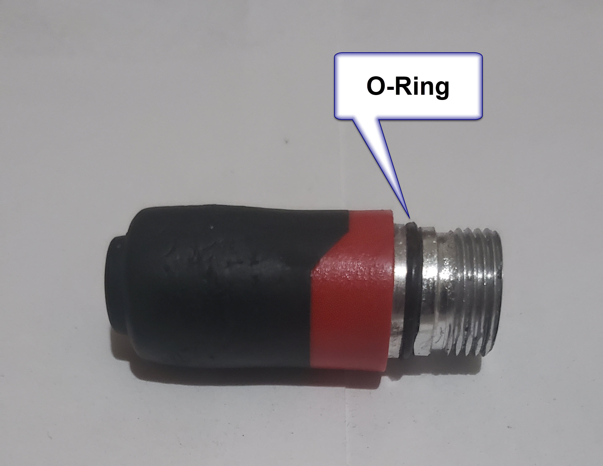 |
| An O-Ring on the end of a flashlight |
As simple as they appear, there's enormous amounts of research invested in that simple, pliable polymer ring.
How does this affect the designer? Typically by the pages and pages (real or virtual), containing tables and tables of o-ring groove dimensions.
 |
| O-Rings from a different flashlight. |
When it comes time to apply that to a 3D modeler, that means creating the o-ring grooves, including some tight tolerances. The process can be extremely tedious, especially when there are multiple o-rings of different sizes involved.
So how can a user create these o-ring glands as painlessly as possible? Sure, many of us have placed the same feature so many times we have the dimensions memorized. But why do that, unless you like that sort of pain?
While I can't speak for every CAD tool, many tools have wizards that will help create o-ring glands, as well as other common design features. Autodesk Inventor has iFeatures, Solidworks has Library Features.
Fusion 360 doesn't have a library feature as such, at least that I've found at this point. But, there is a way to create such a thing and make life a little easier.
Preparing the O-Ring Gland
The first step, is acquire the documentation with the necessary dimensions. Lately I've become partial to the Parker O-Ring Handbook myself, seeing how they know a thing or two about sealing.
For this example, I'll use a -018 o-ring. It's a static (non moving) seal, and I'll use the male gland as an example (stop snickering, that's Parker's terminology).
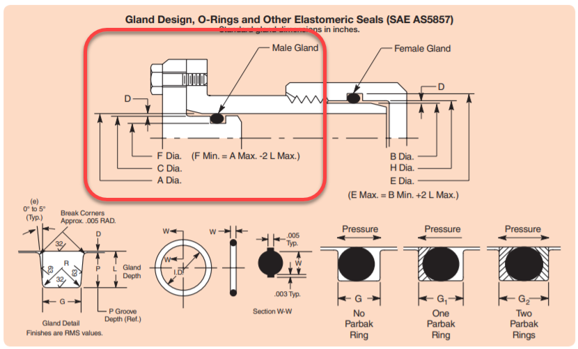 |
| Gland Schematic from Parker O-Ring Handbook |
Here are the dimensions pulled from the design tables
From Table 4-1
C=.860/.861
F = .750/.754
Corner break = .005

From Table 4-1A
W = .105/.110

From Table 4-2
R = .005/.015
 |
| O-Ring Groove Radius |
Modeling the O-Ring Gland
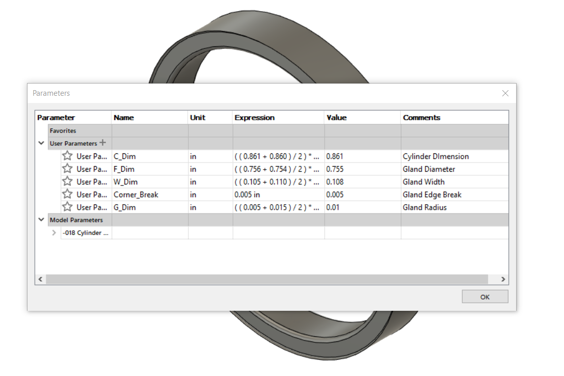
Before creating any models in Fusion 360, enter the relevant values into the parameters dialog box. This seems like extra work, but I think it makes creating models with new sizes easier.
 |
| The Fusion 360 Parameters screen with the o-ring parameters started |
Now, draw the profile of the o-ring gland, using the values from the parameters table.
 |
| The gland profile sketched and dimensioned. |
Next revolve the profile into a solid. Now, we have a solid representing the shape of the groove.
 |
| The o-ring groove revolved as a solid. |
Believe or not, that's it for creating the gland. Saving it will make it available for other components to use.
Inserting the O-Ring Gland
What's needed next is a component in need of an o-ring. In this case, I've modeled a simple plug in Fusion 360. It's similar to the threaded plugs found here on the McMaster Carr site. I've just moved the gland location to make things a little more clear.
 |
| A threaded plug |
To place the o-ring gland, right click on the file in the Data Panel and choose "Insert into Current Design". This places the gland into the model

This inserts the gland into the plug. Now it can be positioned by using the Move/Copy command, or assembled using the Joints command.
 |
| Placing the o-ring gland. The Move\Copy command is shown. |
After positioning the gland, use the combine command to subtract the gland volume from the plug.

Once the Combine Command has been committed, the plug is finished. And you also have a -018 gland ready to use in your next design!
 |
| The finished plug. (Don't forget to hide the original solid!) |
But undoubtedly, other o-ring sizes will be needed. That's where using the parameters can come in handy. Just copy the existing gland and rename it, then enter new values in the chart.
Summing it Up
I only used static o-ring grooves for this post. There's also dynamic (moving) seals, face seals, glands that use backup rings (for higher pressures), and probably something else I'm not mentioning. I just can't get into them all, but the data is out there. It's just a matter of looking and asking questions.
As for desigining the gland, the steps I've shown here are for Fusion 360. But if you've made it this far, I hope it's the process you take away. I hope that you can find it helpful, and perhaps can apply it to what ever product you use for your design.
At the very least, I hope you walk away with resources that you can use when the time comes to design for o-rings.
And lastly, here's the list of resources I used in this post.
Parker O-Ring Handbook - PDF Download
McMaster Carr - Website
Milwaukee Penlight - From the Home Depot Website
Mag Instruments Maglite - Mag Instruments Website
Autodesk Fusion 360 - Autodesk Website