Find us on Google+ May 2013 ~ Inventor Tales

Wednesday, May 29, 2013

Autodesk Vault Ribbon Disappears when Starting a Component in Autodesk Inventor 2014 & a Fix

“You're darn right you're picking up the tab!”
Tony Stewart

A little while ago I ran into an issue with my installation of Autodesk Inventor 2014 that, while not a showstopper, was a little annoying.

Every time I started a new component.  My Vault ribbon would disappear.  That's right, just like Nightcrawler from X-Men, it would Bamf! out of existence.

Image courtesy of Wikipedia

I wasn't doing much work in Inventor 2014 at the time, so I would just unload and reload the addin to temporarily fix the issue. 

Finally, I got off my lazy duff and searched for a real solution. 

And out on the Autodesk Discussion Group.  I found it!

I went a head and moved on.  It quickly began collecting dust in the mental archives. 

But low and behold, a comment on a previous blog brought this back into the light.  So I decided to share it before it slipped into the archives yet again.   

It turns out the solution is pretty simple.   The issue is caused by two instances of the EDM Addin running,


Here's the fix:

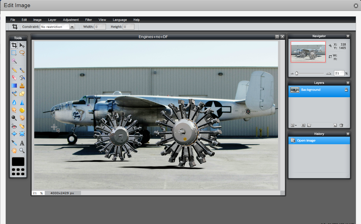
1) In Inventor, go to Tools> Addins
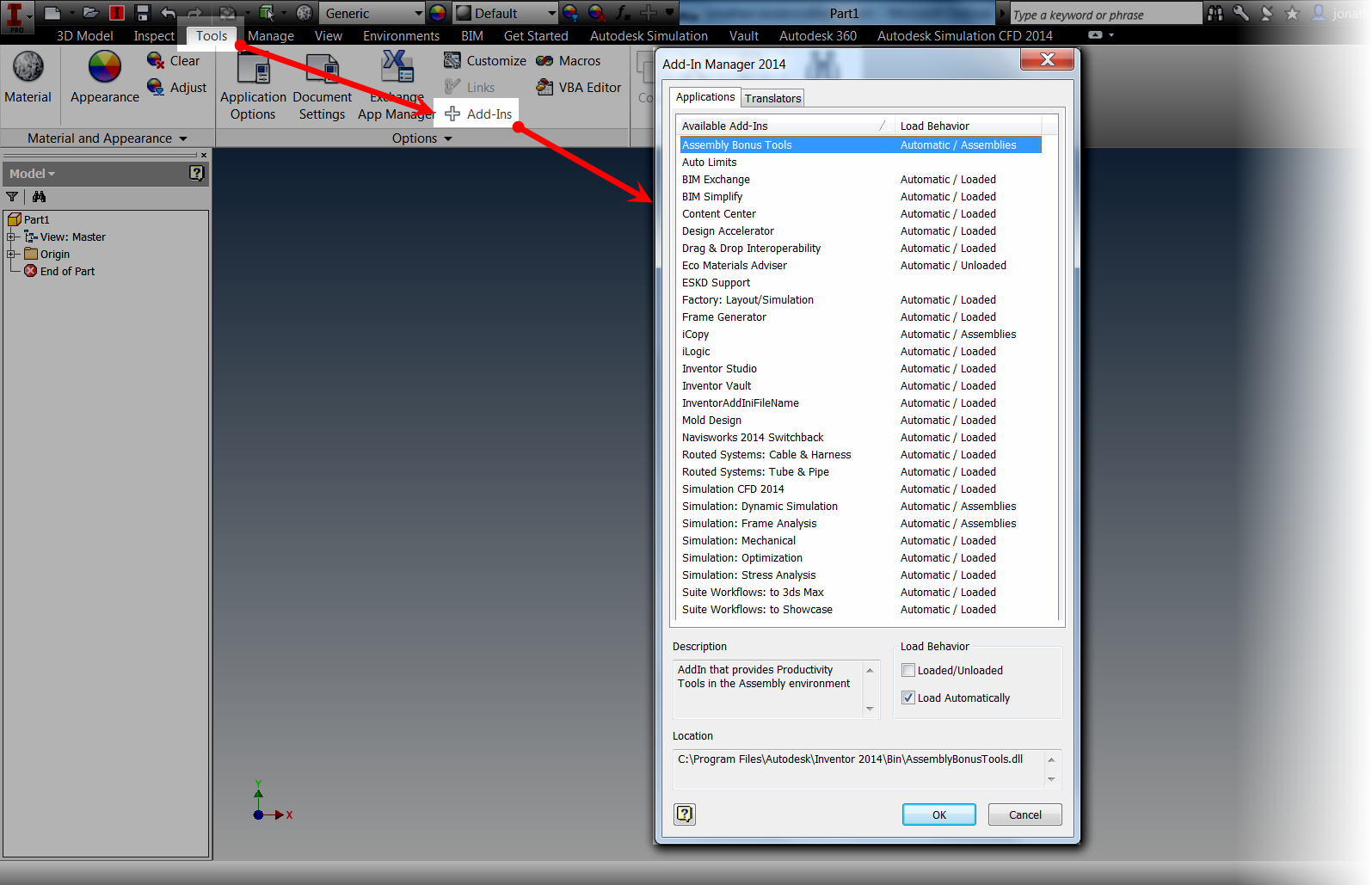


Finding the Addin


2) The EDM Addin is a hidden addin.  To display it, right click in the Available Addins window and choose Show Hidden Members.


Show hidden member

3) Now check to see if there are two EDM Addins.  Left clicking on the Available Addins will sort them and make it easier to find them.


Checking to see if there are two addins

4) Now that the two addins are located, find the one with the location mscoree.dll. Then uncheck "Load Automatically".


5)  Close the dialog box by clicking "OK", and all is done.  The next time Inventor opens, the Vault tab should appear just fine!


All is good!

Acknowledgements

While I would love to say that I found this solution on my own, and "stake my intellectual flag" on it.  I did not.  I found it off the Autodesk Discussion Group at the link HERE

Thanks to the users who shared what they have found, their assistance is far reaching indeed!


Sunday, May 26, 2013

A Tour of Constraint Relationships in Autodesk Inventor 2014

“Let's think of new opportunities, not past constraints, as we visualize the future of the state that we call home.”
Kathleen Sebelius

Sitting in my hotel room on a business trip to Dallas, Texas, I found myself taking a look at a new feature in Autodesk Inventor 2014, and thought I would go ahead and create a short post on it.

This new feature is "Show Relationship" in an assembly. 

Activating this feature shows the relationships between constraints in the modeling window, in a graphical format.

For this example, I'll use the Craftsman style coffee table I've used dozens of time before.


The constraint relationship glyphs showing on the Craftsman Style Table


By using a graphical representation, the constraint can be easier to visualize, modify, and delete.

The first step to using the relationship is to show them.  This is located on the Assemble Tab by clicking the Show icon.

The Show Relationships tool


Once the icon is selected, I can choose the components I want to show the relationships for.  In this case, I'm just going to look at the table top.

Glyphs will appear where the constraints between the table top and the lower table it's connected to.

The Constraint Relationship glyphs

Right clicking on the constraint glyphs provides the operations that can be performed on this constraint, such as, Edit, Delete, and Suppress, among more.

Right clicking on a glyph will show the editing tools


If the component is moved using the Free Move command, "bands" appear that connect the constraint to its mating components while the command is active.  After this I can right click and choose "OK" to complete the move.

Using the Free Move command to separate components


Clicking on the constraint will also highlight the geometry that the constraint is attached to, giving a quick graphical way of seeing how the constraint is being used to constrain the geometry.  Just like before, right clicking on a constraint will show the options for that constraint

The components move apart, showing the right click options

Updating the assembly will update the constraints and return the component to its original position.


Updating the assembly will restore the constraints

But before I say "take this tool for a spin", there is on other place this tool can help out.

If there are "sick" constraints, such as conflicting constraints, can be graphically diagnosed using the Show Sick Relationships tool.


Showing Sick Constraint Relationship for diagnostic purposes.

With this ability, the Show tool can be used for editing, and for diagnostics!

So on that note, take this tool for a spin!  And in addition, here's a video on the subject!


Sunday, May 19, 2013

Updating to a New Release of Autodesk Inventor - Refresh from Content Center

“You do not destroy an idea by killing people; you replace it with a better one.”
Edward Keating

This weekend's blog post, by nature, has to be a short one, and without video.  This weekend I'm between trips out of state, so I've been busily trying to get caught up, and prepare to leave town again.

Much off this consists of unpacking into the washing machine and directly packing it again! 

But in the spirit of "unpacking and cleaning up", here's a little tip that can help in making the Content Center fasteners in Autodesk Inventor's Assemblies are "cleaned up" as they are moved to 2014

I'm going to start with a Craftsman Style coffee table that I've had in my archives for several years now.


This table uses No 8 x 1.0 inch wood screw that I placed from content center.


But now, these files are old, created from a 2013 library, and not a 2014 library.  So what's one way to make sure that those files are made current.

1) If Autodesk Vault is being used, make sure to check out all the files from Vault.


2) One the Manage Tab, choose the "Refresh Standard Content" Icon.


3) Inventor will display which content is in need of refreshing.  If several different components are being used from Content Center, then multiple components can be selected (or not) in this dialog box.


4) Click the Refresh icon to update the content from the Content Center Libraries.


5) Now all that's left to do is save the assembly, and, if Vault is being used, check the file in.


For some more info on updating the libraries, including migrating custom content libaries from an earlier release of Autodesk Inventor, check out the link on Autodesk Support here!

Sunday, May 12, 2013

Placing an iFeature from Autodesk Vault 2014 - New for 2014!

“Burglars know there's more than one way to skin a vault.”
James Chiles

Early this week, I had a chance to play with an intriguing new feature of Autodesk Vault 2014. 

It's the ability to add iFeatures to, and place iFeatures using Vault.

I'm going to definitely use this tool in my personal projects.  I've created plenty of features in my day, and many times, I recreate them because I'm careless and lose them, forget to migrate them, etc.  I can get creative when losing iFeatures.

Trust me!  No matter how many times I tell myself I'll be more careful, I've sent many an iFeature to the "Land of Lost Files"!  Vaulting iFeatures will definitely reduce lost iFeatures in the future.

But, is it set up to work with Vault? 

I don't claim to have all the tricks figure out.  I'm still trying some things out, but here's what I've discovered so far.  Take my ideas, modify them, tweak them, and use them for inspiration. 

The first thing I did, was choose a folder in my Vault Workspace to store my iFeatures.   I also copied my default iFeatures here, so I can use them if I want.


Why?  This will prevent this error, when trying to check in iFeatures from the default Inventor location!  This error is caused because the default iFeature location isn't located in the Vault Workgroup path.

This is an error.  Years of experience have taught me that errors are bad.
I'm also going to change Inventor's default iFeature location to match the workspace.  This will make sure that I'm always using the same iFeatures I've Vaulted, even if I don't place the iFeature directly from Vault.

First, I change the default iFeature location in Tools>Application Options>iFeature Tab.  Note that sheet metal punches are a special class of iFeature, so I'm going to change that location too.

The new locations specified in Inventor's application options
 Now, an iFeature can be checked in and out of Vault, and enjoy all the benefits of being stored in Vault!

Checking into Vault

Once it's checked into Vault, now it can be placed from Vault onto a part that needs it.

Placing an iFeature from Vault
And after that, it's just like an iFeature has been place for years!

And it's placed
And here's the video version of the process!


One thing I have noticed, is that this tool doesn't work with sheet metal punches.  So I've decided that I'll have punches Vaulted but keep them in my local workspace, using the settings I created above.  Maybe we'll see that one come in the next release!

Thursday, May 09, 2013

Changing Autodesk Showcase Model Orientation After Importing from Autodesk Inventor - A Guest Video

“For many people, one of the most frustrating aspects of life is not being able to understand other people's behavior.”
Anonymous

Autodesk Showcase has a lot of tricks up it's sleeve when importing models.  But that leaves the challenge of knowing when to use which trick. 

One challenge, I know I've always faced is importing Autodesk Inventor Constraints as Behaviors in Showcase.  I don't do it often, so I find that I figure out how to use them for a scene, but then I don't use them for a while.


The next time I need to use them, I've managed to forget everything I learned, so I have to relearn it again! 

But as many a teacher has reminded me over the years, "It's not about knowing information, it's about knowing where to find information".

So here is another guest video by Marion Landry on how to use import settings in Showcase to make sure you get the results you want!  It gave me some more ideas on import tricks, and I'm sure others will find it helpful too!

Thank you, Marion!!


Wednesday, May 08, 2013

Controlling the Visibility of Multiple Sketches on an Autodesk Inventor Drawing

“I do a bale of sketches, one eye, a piece of hair. A pound of observation, then an ounce of painting.”
Gardner Cox

In a blog post a "few moons ago", I discussed how to get model sketches and show them on a drawing in my post: "Using Model Sketches on a Drawing in Autodesk Inventor". 

In that post, there was a comment that stated once the sketches were made visible, the option to "Get Model Sketches" was grayed out.  Which is true. 

Get Model Sketches is now grayed out


So how can the visibility of sketches if they're added to the model after the "Get Model Sketches" option is used.

Here, I've added a second, distinct sketch in Autodesk Inventor 2014.

Note the sketches are separate

When I switch to the drawing, the sketch will automatically appear on the drawing, with no further interaction.
The second sketch appears

But what if I don't want to show both sketches.  Perhaps one sketch represents a spot weld, and the other is just there for construction or a model only reference?

All that I have to do is right click on the sketch in the browser, and uncheck the "Visibility" option.  The sketch will disappear and will no longer be shown.  Showing the sketch will make the sketch visible again.


Now you see it!

Now you don't!

 Being able to control the sketches individually adds more flexibility that an "all or nothing" approach.  So take a look and see how you can use it!

Monday, May 06, 2013

That Time of the Year - Migrating Templates to Autodesk Inventor 2014 Using Task Scheduler

“Are you suggesting that coconuts migrate?"
Monty Python

In a previous post, I talked about migrating Styles from a previous release of Autodesk Inventor into Autodesk Inventor 2014.

The simplest way, of course, is just to open each file in Inventor and save it.  This will migrate the files.

And it does have it's advantages.  Opening the file would allow for an "inspection".  Old styles could be inspected and purged, new styles can be added, and general clean up could be performed.

But another way to quickly migrate files would be to use Inventor's Task Scheduler.  This tool allows for the templates (and any other file for that matter), to be migrated in batch, hands off.

Note!  Before migrating any templates, make sure you've backed everything up!  I've never had a problems with migration, but you only have to be wrong once! 

 To access Task Scheduler, go to Windows Start>All Programs>Autodesk Inventor 2014>Tools.  Task Scheduler will be in there.

Finding Task Scheduler
Selecting the icon will open Task Scheduler for use.  Choosing Create Task>Migrate Files will bring up the dialog box to set up migration tasks. 


With the Migrate Files dialog open, now the settings for migration can be configured.

There are several settings that can be changed for this dialog.  Some of the major ones, and my preferences for this task

Project: The project under which the files will be migrated
Vault: Migrates the files out of Vault - Since my templates are not in Vault, I won't be using this setting
Folder icons: Are the files going to be added individually, are folders going to be added, or is an entire project going to be migrated?  I'm going to use folders

Under Task properties, it's also possible to give the task a name (I just use default), and schedule the task for a given time.  Since my templates aren't particularly large, I'm going to run them immediately.

The Migrate Files dialog.

In the dialog below, I've added the folder to migrate, and completed my settings.  I also like to click on options, and have the Task Scheduler Skip Files with Unresolved References, Purge Old Versions, and Compact Model History.  

If these were parts with features, I'd also compact the model history, but these are mostly empty templates.

Setting up options

Once the settings are ready, I can close the Migration Options, click OK, and start the migration.

Committing the migration

The migration will begin running.  For templates, this typically takes a few minutes, but it does depend on how many files are being migrated, so that has to be taken into consideration before starting.

Once the notification is completed, right clicking on the task will allow for a report to be generated that will show which files were successful, and which files failed and why. 

Finished!
But those are the steps to migrate files.  Here I've used them in templates, but they're not limited to just template files.  This is valid for any Inventor files, so remember that it's available for use!

If you prefer the video form, just take a look below!


Wednesday, May 01, 2013

A Quick Tour of the Pixlr Photo Editors Included in Autodesk 360

“the highest regard you can receive. That photo can describe an entire life, just an honor, as well as a fun moment.”
Aaron Eckhart

One of the things Autodesk Showcase can do is publish renderings both locally, and to the cloud via Autodesk 360.

Rendering an image both locally and to the cloud
But one of the things I recently learned, quite by accident, is that Autodesk 360 will do more than just store the renderings for safe keeping and sharing. 

It also contains tools from Autodesk Pixlr, which allow for additional photo editing to the image even after it's been rendered from Showcase.  So additional effects to make for a more eye-grabbing image can be created if desired. 

Before, I only knew this tools to be available for mobile devices, I hadn't realized they'd made their way to Autodesk 360 too!

These tools can be access by using the "Actions" pull down in Autodesk 360.   There the tools Pixlr Editor (Advanced) and Pixlr Express (Efficient) are located.

Below I'm using the scene I used from my previous blog post on the "Depth of Field" settings in Showcase 2014.


Choosing the editor
Selecting Pixlr Express, the editor will open and allow effects beyond what was created in Showcase available. 


The effects toolbar
The effects include things like:

Adjustment: Find tools like, Rotate, Blur, Resize, Rotate, etc. to images.
Effect: Tools to soften, age, make unicolor, etc. to images.
Overlay: Overlay effects like Flame, Fireworks, and more.
Border: Add several different borders to the image
Sticker: Several "stickers" are available to place on the image.

Below is an image in the process of having an effect added.


Editing the image.

When all is done, a new image with new effects is created and can be used.  So if there's a need to tweak an image, or just create something with a little more "artistic flair", the Pixlr tools on Autodesk 360 can be a nice way to add what's needed.

Below is the completed image, with an aging effect and a border added. 


And don't forget, there's also Pixlr Editor, which adds a lot more tools for even more photo editing options!

Pixlr Editor for more editing tools
 Below I've used it to to remove the truck in the background from another rendering created off the same scene.


Note the truck in the background on the left side.

I'm not much of a photo editor, so it's not difficult to see my edits.  Someone with a little more skill can do a much better job.

The truck hidden!  Even though the user's skills aren't very good!
 So there we are.  Some of those little known tools inside of Autodesk 360.  But if needed, they'll be there to add more punch to an image.

And on a final note, everything I've done has been using Autodesk Showcase, but any image can be edited.  So that means images created from an program, or even a photograph can be manipulated.

Below is an image I took in Lake Tahoe in Summer 2012.


And now one with a few effects added.


All that's left is for you to give it a try!