Find us on Google+ Inventor Tales: Sheet Metal
Showing posts with label Sheet Metal. Show all posts

Friday, June 30, 2023

Why Combine Two Different Radii Fillets in One Feature? - Food for Thought for Autodesk Inventor and Fusion 360

 Once upon a time, I was asked, in reference to Autodesk Inventor and Autodesk Fusion 360, "Why would someone want to have a fillet feature with more than one radius in it?" 

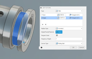
An example of two different fillet radii in Fusion 360

It's a fair question. It's likely we can pick a feature in just about any CAD tool and ask, "Why is that there?"


But to that end, I did have a reason one might want to combine two different fillet radii in one feature. 

It's a matter of organization. In my design work, I often find myself modeling O-ring grooves, which nearly always have a different radius at the top and the bottom of the gland. Having the ability to combine the different radii in the same feature allows me to combine the fillets into a "O-ring Radius Feature", and maybe shave down the feature tree a little bit. 


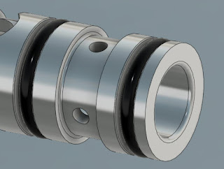
An O-ring groove using two different radii fillets in the gland.


O-rings installed in the glands.
Just to give some context to the first image.

Another case I've used was way back when I was designing sheet metal tooling. I used it when "keying" a rectangular insert. In that example, the opening has 3 radii of one size, and the fourth is a different radius. The insert has chamfers of a similar size. This prevents the insert from being inserted in the wrong direction. Why fillets on the opening and chamfers on the insert? It was easier to machine with the tooling of the time!

An example of a sheet metal stamping insert


The"keying" feature up close.


Admittedly, these two example are very specific to my own design experience. But perhaps it might give someone food for thought.

While you might not run into one of these particular examples I've described, maybe there will be something similar that you can use.  

Is it life changing? Not very likely. But maybe it's a little food for thought as you make your way through the 3D CAD world. 

Monday, May 29, 2023

Drilling for Truth - Implied Drill Tolerance

First, I have to start with my big disclaimer.

While I've had experience with drawing standards, I don't consider myself a full blown expert. There is so much detail in standards, I can't say I'm an authority on all of them. 

Also, living in the United States, I work in the ANSI/ASME standards.  

My apologies to those who are living the ISO life (which is basically everyone who isn't the United States), I'm only acquainted with that standard. 

So this post will be based on "freedom units", that is feet, inches, and bald eagles. 

Joking aside, I hope this post is entertaining at least. Onward to the post. 

My current place of employment has a lot of legacy drawings. It's not uncommon to find a scanned drawing from the 1970s in our data management system.

It's like digital archeology! 

One of the things I find can be a big challenge, and very interesting, is interpreting dimensions, notes, and callouts that have fallen out of favor over the years.

Recently I was part of a discussion regarding a hole callout on one of these old drawings. 

The callout stated "Drill" and called out a specific drill size. In the case of the screen capture shown below, the drill size called out is a #30 drill, which is .1285 inches in diameter. But even the diameter is called out as a reference dimension. 

The really interesting thing about this callout is that it implies it's own tolerance, in accordance with AND10387. The tolerances are based on the size of the drill, and a screen capture is shown here from Engineers Edge. You can even see that it has a link to AND10387


But now comes a plot twist. According to Everyspec, AND10387 was cancelled for new design and is only used for "replacement purposes". No new standard is shown to supersede this one. So what does that mean? I wasn't able to find a specific standard that states specifically how to handle drilled holes now. But my experience has taught me that, if required, a tolerance will be implicitly stated next to the dimension. If no tolerance is stated with the dimension, then the block tolerance will be used.
A hole with the tolerance implicitly stated
Since AND10387 is only valid only for replacements, there's a good chance you may never see a drawing with an implied drill tolerance. But there's always a chance an old drawing will rise from the depths. So perhaps it's a good reference to keep in the archives! And if anyone is aware of a standard that calls out standard drill tolerances, or if you just "do it another way", feel free to leave a comment.

Saturday, March 28, 2020

A Challenging Channel - Modeling a Sheet Metal Channel in Fusion 360

On a morning this weekend, while hanging out at home with my coffee in my hand, I decided to play with Fusion 360.  I had a part picked out that looked simple enough.

The finished part. It looks simple, but it hides a suprise

The part I chose looked to be a simple sheet metal part.  It looked to be a simple enough part, but it did have a joggle in it that complicates things a bit.

The joggle that changed how this part was made
Since it's got this joggle, it can't be easily modeled using sheet metal tools.

The sheet metal version wasn't quite what I was after.
So I decided to model it using the "regular" modeling tools.

I also decided I'd document how I did it here, for both posterity's sake, and in the hopes that it might give another struggling user an idea.  I won't go through every single step, but I will give an overview that hopefully encompasses the high points.

The first thing I did was model the envelope.  I nothing more than an extruded rectangle.  A "brick".

The starting point. An extruded rectangle representing the parts outer dimensions.

Next came the process of carving out the shape. I started with the joggle.

The joggles cut into the part. I've turned one of the sketches on to make it more visible.


Once the joggle was in, it was a matter of adding the remaining features, including the outside fillets that represent the outer bend radius.  Notice that the part is still a brick.  It's just a brick with some nice looking features!

The brick has all the features of the sheet metal part now.
This is where my original plan went wrong. My plan was to use the shell command to create the inner profile.

But for some reason, I couldn't select the surfaces I wanted.  I always ended up selecting a surface I didn't want.

So it was time for plan "B".  I switched to the surfacing workbench and used delete face to remove all the faces except those that represented the outer profile of the part.

The part with all but the outer profile removed.  
Now that I had only this surface, I was able to return to the solid workbench and use the thicken tool to get the final shape I needed.


In Conclusion

So is this the only way to do it?  I doubt it.  But it did get the result I was after in a way I was happy with. I'm sure someone out there has a different way of doing it, they may prefer it.  And maybe someone out there has a way that's truly better.  I would be thrilled if they do and I hope they share it!

How would this part be made in real life? 

This is one place that I'm not an absolute expert, so I encourage others to chime in.  But I do have some experience making sheet metal this way.

In production, a blank would be placed in a die, possibly using two of the holes to locate the part.  Then a press would push the two die halves together, forming the part in one operation.

Here's a pretty good video on this process used for the ribs on an aircraft wing.

If the part is made in low production, A form block can be used, made out of wood or metal.  The blank is then formed using a hammer.

He's a video on that process. While this video shows the process being done for steel, aluminum would be done in a similar manner.

The part I modeled in Fusion 360 calls for 24ST aluminum, which is the equivalent of 2024-T3. I know that 2024-T3 can crack when formed around tight bends, so it's possible they would have used 2024-0 (dead soft) and heat treated to the -T3 condition afterward.  But that's one place I'd have to defer to the sheet metal experts, feel free to chime in!

And that's it, I hope this video was informative!

A Final Addendum, Murphy's Law Strikes! 

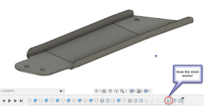
As I finished up this post, I tried the shell one more time.  Guess what! It worked! It seems I was just not quite getting the picks and clicks right when I tried it earlier.  But I decided to go ahead and share the post anyway because I still feel it's a viable alternative. 

It figures! The shell does work!


Sunday, August 27, 2017

Restarting a Line in a Fusion 360 Sketch

My story of late has been building a few parts in Fusion 360 over the course of a few evenings.

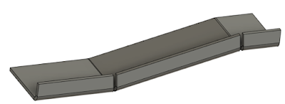
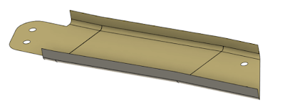
Another sheet metal part I'm working on.
And with that practice, comes a few simpler tricks to help models get built a little bit more efficiently.


It's been a series of sketching, extruding, and now that Fusion 360 has a sheet metal module, it's included adding flanges.

Making these parts means drawing a lot of lines to build parts.  But part of drawing these lines sometimes means creating a line in one place, completing it, then creating another line in a different place on the sketch.

If I were using Inventor, I would right click and choose the "Restart".  That would finish the line being drawn, but remain in the command so another line could be started elsewhere.

It's a simple command, but one that I know I've found helpful.

But looking at Fusion 360 there is no repeat command.  At first blush, it would appear that it isn't possible.

But before wishing an overworked programmer a pox upon his soul, I thought I'd see if another tool might give me the behavior I was looking for.

And I found it!

All I had to do was right click and choose Repeat Line.  It's a slightly different command, but it did exactly what I was after.  It gave me the ability to finish the line command where it was, and restart it in a new spot.  And I didn't have to exit and restart the command.

It's a workflow in just about every CAD program that will allow me to use it.  I'm big on placing holes on lines and vertices of rectangles.

So if that's a workflow you're also used to, give it a try in Fusion 360!  It might be a way to make things run a little smoother!

Creating holes using lines, a trick I like using.