“For this relief much thanks; 'tis bitter cold
And I am sick at heart.”
William Shakespeare
Once again a busy travel week has made my life hectic enough that I'm not able to create the video that typically goes with most of my posts.
But with another busy week ahead, I've decided to press forward and create a text only post to describe a new feature that I've had a chance to use to great effect in Autodesk Inventor 2014.
That feature is Show
Sick Constraints.
As some may know, I've been slowly trying to rebuild a 9 cylinder radial engine in Inventor. I found the original model on
GrabCAD in Solidworks and several neutral projects, and decided to take it on with a long term goal to rebuild it completely in Inventor.
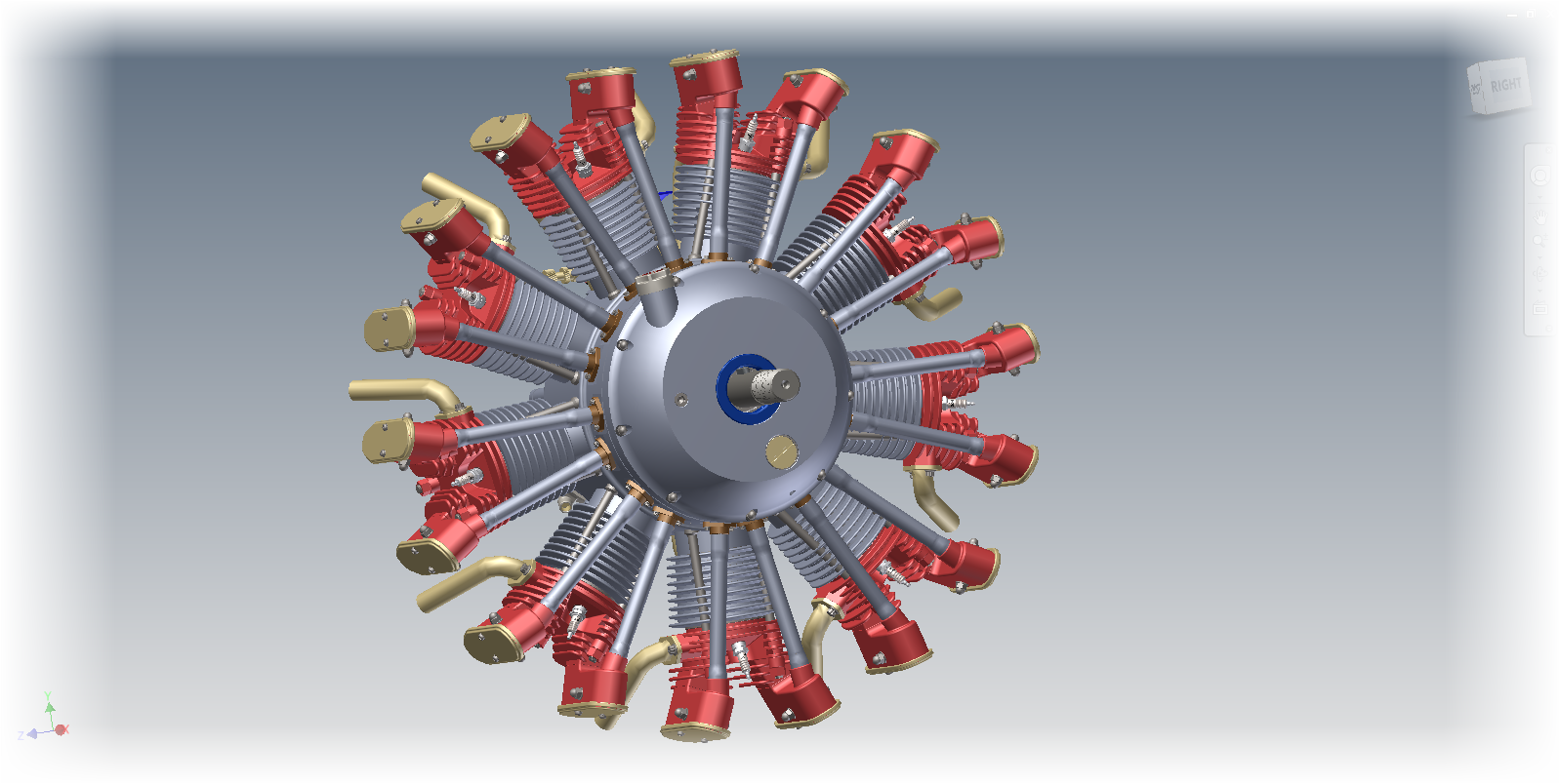 |
| The entire engine. This one is a Parasolid model imported into Inventor |
I work on it here and there, so I suppose it's going to take a long time to finish it!
One challenge I encountered was a simple one. I was assembling bronze bushings into the engine core, there were two per cylinder, and 9 cylinders total. So an Associative pattern readily took care of this.
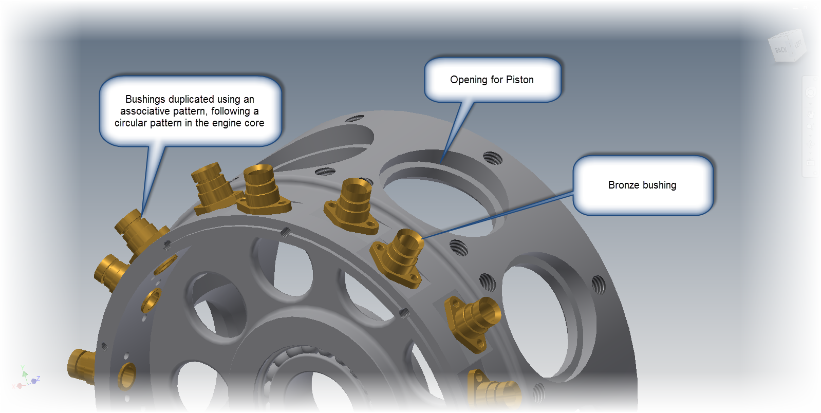 |
| The components. The bushing is placed. I need to change this to a subassembly containing the bushing and bolts |
However at this moment I realized my mistake. I had meant to put in a subassembly containing the bushing, and the bolts.
However, in my haste, I had only put in the bronze bushing as a part.
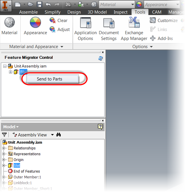
This was easy enough to fix. All I had to do was to switch my selection filter to
Select Part Priority.
Then I selected one of the bushings, and use
Replace All Components to switch to the assembly I had intended to put in.
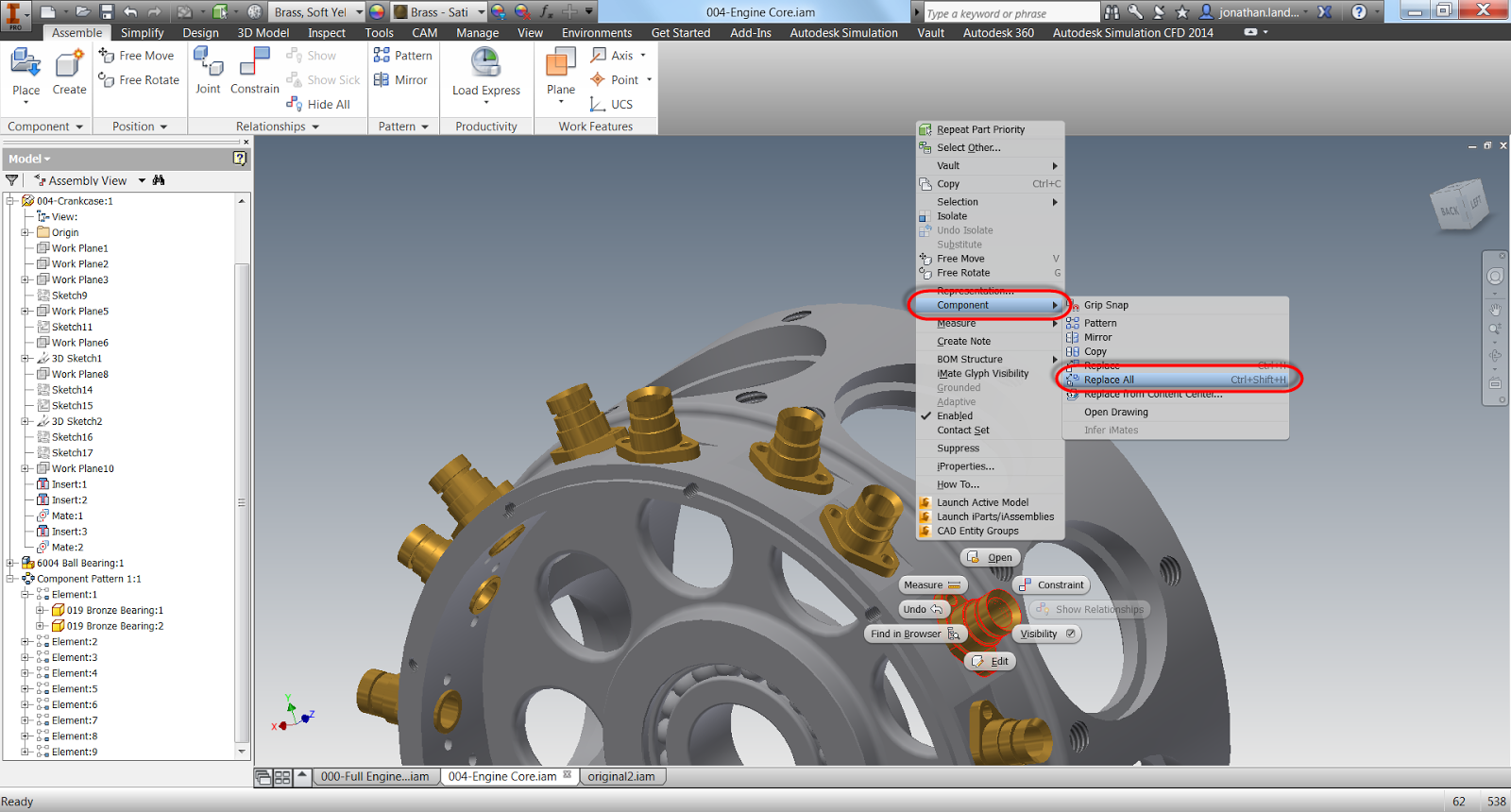 |
| Replace All Components will let me change out all the bushings. |
It let's me browse out and get the assembly I had intended to place, but now I have a problem. The constraints have broken, and I have to fix them. There's four, two for each bushing I had placed. The other sixteen aren't a problem, once I fix the originals, they'll fix themselves.
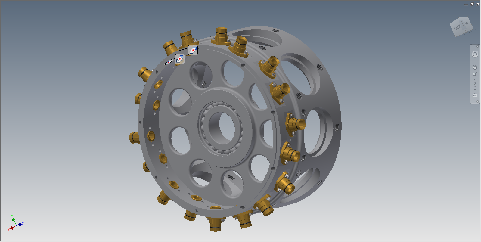
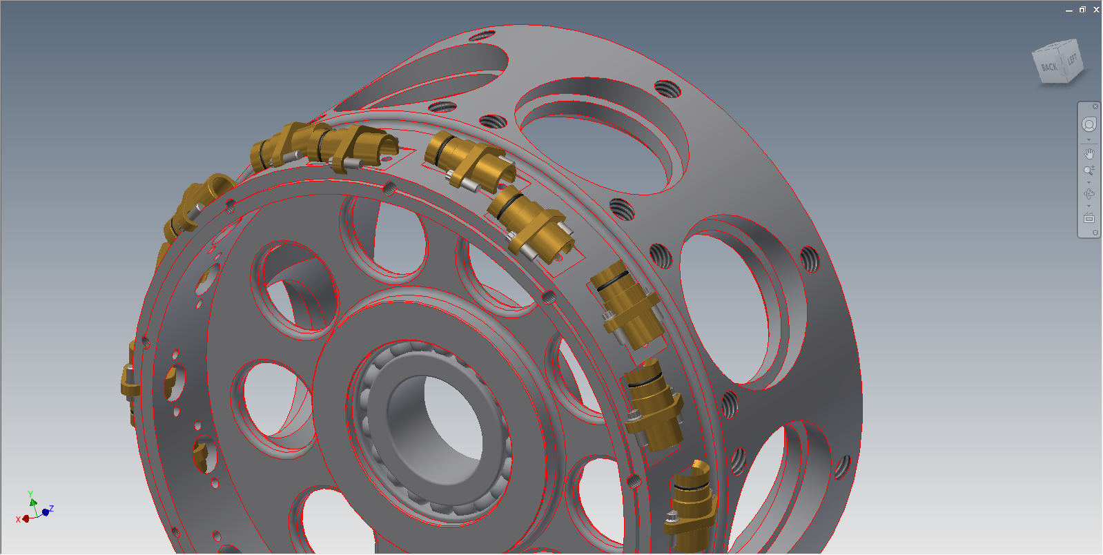 |
| The bushings are rotated sideways because the constraints are "sick" and need to be fixed. |
But now I have to find the constraints......
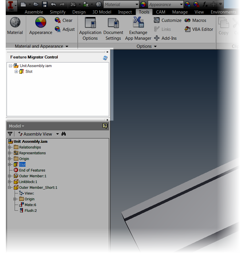
Fortunately, Inventor 2014 has a new function called
Show Sick Constraints.
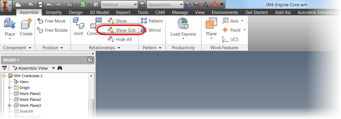 |
| The Show Sick Constraints icon |
By clicking this icon, the sick constraints are graphically shown as glyphs on my screen. I don't have to fish through the browser to find which they are and address them.
 |
| The Sick Constraint Glyphs. |
Now I can select one of the glyphs, right click, and choose
Edit.
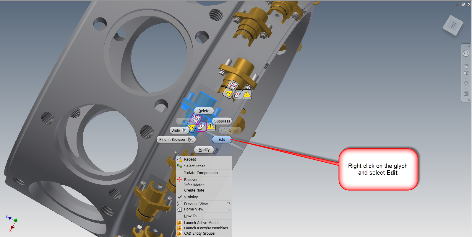 |
| The screen capture is a little busy, but right click on the icon. |
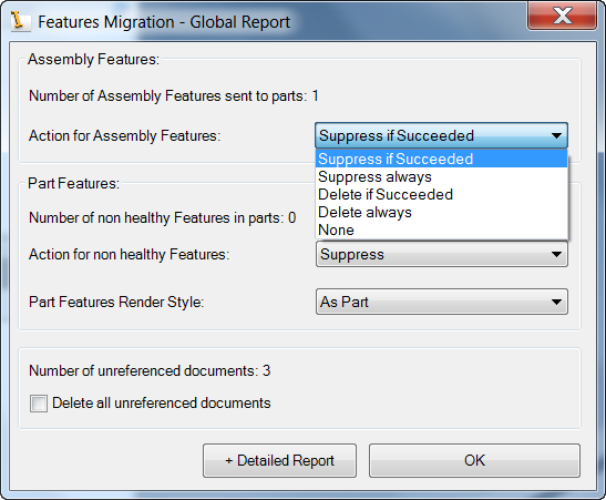
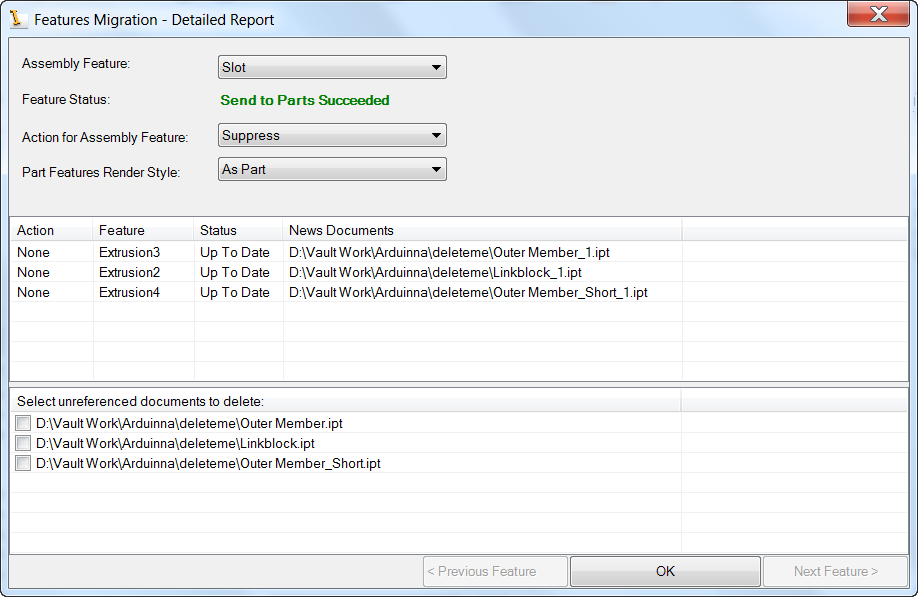
The
Edit icon brings up the
Constraint Edit screen. Now I can re-associate the constraint that broke on me.
Note that in the screen shot below, I've already fixed one bushing.
I just click the icon, and select the geometry I want the constraint to act on.
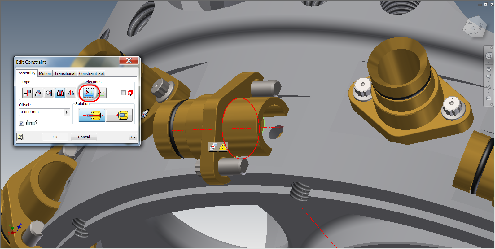 |
| Fixing the Insert Constraint |
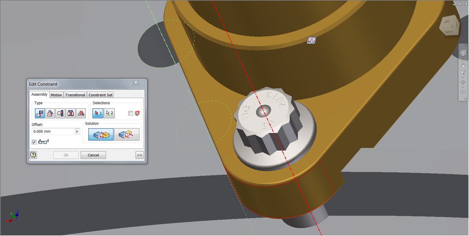 |
| Fixing the Mate Constraint |
Once all the constraints are fixed, I can now see that the rest of my pattern has reoriented itself too.
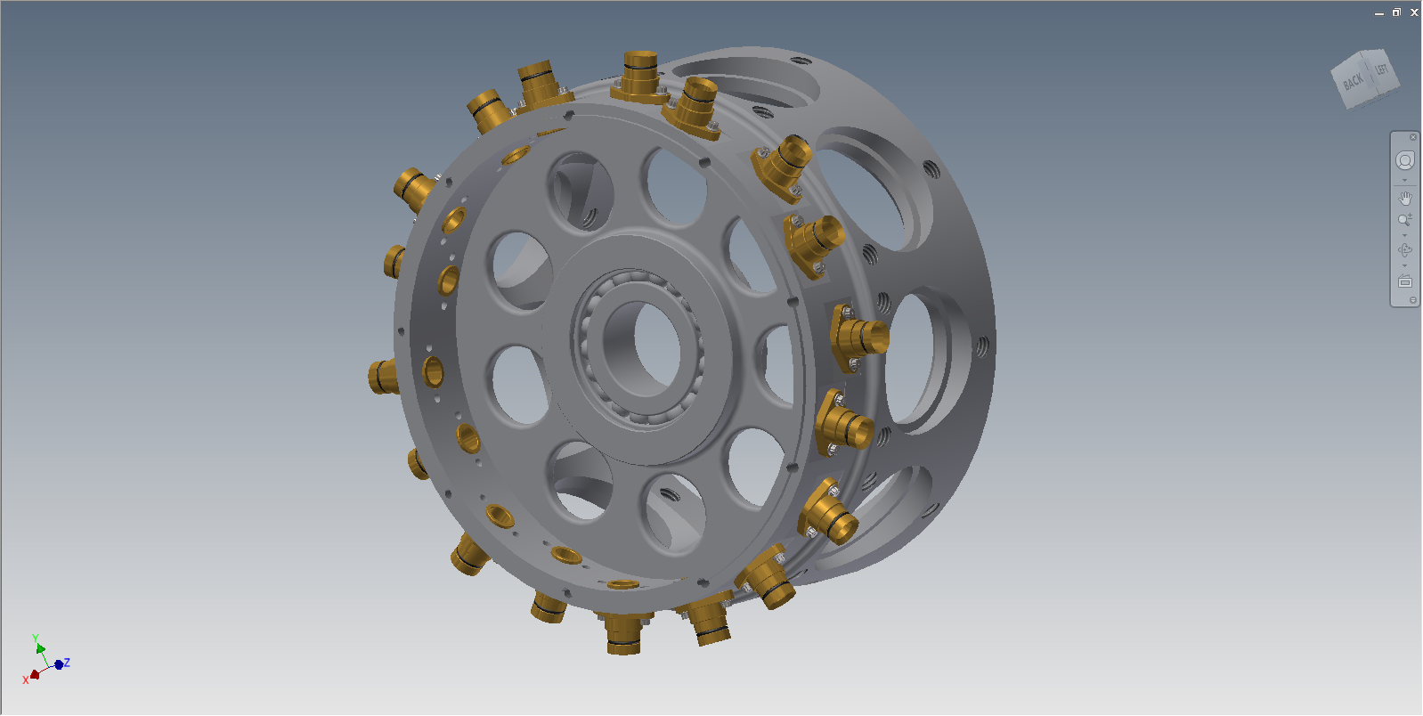
 |
| The engine core with the correct assembly |
The constraints, now repaired, still show their glyphs on the screen. Now I can use the Hide All Constraints" icon to remove the glyphs.
 |
| All done! |
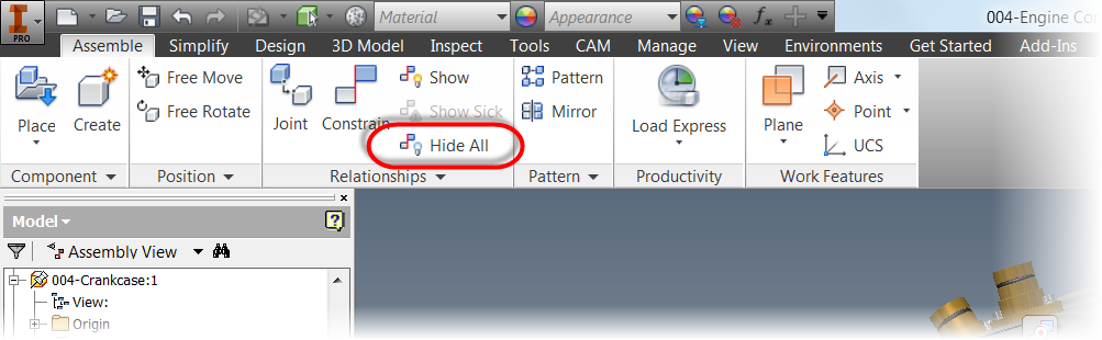 |
| Hiding the glyphs. |
After clicking the Hide All Constraints icon removes all the glyphs on the screen, and now I'm back in business!
If you have Inventor 2014, or you're thinking of going to it. Take a look at this feature! It's well worth it!
For other new features with Assembly Constraints in Inventor 2014. Check out my previous post on
Constraint Relationships.
Acknowledgements:
I have to thank Dave Goetsch for sharing this file on
GrabCAD, Without his work, I wouldn't have been able to write this post. Check out his excellent work on this and other projects.


