Find us on Google+ Inventor Tales: Cloud
Showing posts with label Cloud. Show all posts

Saturday, January 08, 2022

A Milestone Creating a Fusion 360 Title Block!

I have completed the task I challenged myself with in my previous post. I finished up my reproduction of a 1940s era North American Aviation title block in Autodesk Fusion 360!


The original, and Fusion 360 Title block together


It was a little tedious at times, it's a lot of repetitive sketching geometry and inserting text and properties. 

But it's completed, and ready for use. I'm sure I'll find a few more things to adjust as I test it out. 

Ultimately, I was able to recreate nearly every feature of the title block. It's not an exact match. I couldn't find a solid fill to block out the box above the part number for example. But it is close, and it will serve it's purpose just fine. 

As more features get added to Fusion 360, I'll update the title block accordingly. 

The North American Aviation tile block finished

So now, it's time to start creating drawings! From there, I'll learn more lessons and make more adjustments!

Credits:

Title Block Sourced from my Aircorps Library subscription.

About the Author:

Jonathan Landeros is a degreed Mechanical Engineer and certified Aircraft Maintenance Techncian. He designs in Autodesk Inventor, Siemens NX, at work, and Autodesk Fusion 360 for home projects. 

For fun he cycles, snowboards, and turns wrenches on aircraft. 


Friday, July 31, 2020

Designing for O-Rings and Reusing Design Features in Fusion 360

O-ring seals are hard to avoid as a mechanical designer of any type. They can be found just about anywhere that fluid, gases, or debris needs to be kept in or out of something.

An O-Ring on the end of a flashlight

As simple as they appear, there's enormous amounts of research invested in that simple, pliable polymer ring.

How does this affect the designer? Typically by the pages and pages (real or virtual), containing tables and tables of o-ring groove dimensions.
O-Rings from a
different flashlight.


When it comes time to apply that to a 3D modeler, that means creating the o-ring grooves, including some tight tolerances. The process can be extremely tedious, especially when there are multiple o-rings of different sizes involved.

So how can a user create these o-ring glands as painlessly as possible? Sure, many of us have placed the same feature so many times we have the dimensions memorized. But why do that, unless you like that sort of pain? 

While I can't speak for every CAD tool, many tools have wizards that will help create o-ring glands, as well as other common design features. Autodesk Inventor has iFeatures, Solidworks has Library Features.

Fusion 360 doesn't have a library feature as such, at least that I've found at this point. But, there is a way to create such a thing and make life a little easier.

Preparing the O-Ring Gland

The first step, is acquire the documentation with the necessary dimensions. Lately I've become partial to the Parker O-Ring Handbook myself, seeing how they know a thing or two about sealing. 

For this example, I'll use a -018 o-ring. It's a static (non moving) seal, and I'll use the male gland as an example (stop snickering, that's Parker's terminology). 

Gland Schematic from Parker O-Ring Handbook

Here are the dimensions pulled from the design tables

From Table 4-1

C=.860/.861
F = .750/.754
Corner break = .005 


From Table 4-1A 

W = .105/.110 


From Table 4-2

R = .005/.015 

O-Ring Groove Radius

Modeling the O-Ring Gland

Before creating any models in Fusion 360, enter the relevant values into the parameters dialog box. This seems like extra work, but I think it makes creating models with new sizes easier.

The Fusion 360 Parameters screen with the o-ring parameters started


Now, draw the profile of the o-ring gland, using the values from the parameters table. 

The gland profile sketched and dimensioned.

Next revolve the profile into a solid. Now, we have a solid representing the shape of the groove.

The o-ring groove revolved as a solid.

Believe or not, that's it for creating the gland. Saving it will make it available for other components to use.

Inserting the O-Ring Gland

What's needed next is a component in need of an o-ring. In this case, I've modeled a simple plug in Fusion 360.  It's similar to the threaded plugs found here on the McMaster Carr site.  I've just moved the gland location to make things a little more clear.

A threaded plug

To place the o-ring gland, right click on the file in the Data Panel and choose "Insert into Current Design".  This places the gland into the model


This inserts the gland into the plug.  Now it can be positioned by using the Move/Copy command, or assembled using the Joints command.

Placing the o-ring gland. The Move\Copy command is shown.

After positioning the gland, use the combine command to subtract the gland volume from the plug.  


Once the Combine Command has been committed, the plug is finished.  And you also have a -018 gland ready to use in your next design!

The finished plug. (Don't forget to hide the original solid!)


But undoubtedly, other o-ring sizes will be needed.  That's where using the parameters can come in handy.  Just copy the existing gland and rename it, then enter new values in the chart.


Summing it Up

I only used static o-ring grooves for this post.  There's also dynamic (moving) seals, face seals, glands that use backup rings (for higher pressures), and probably something else I'm not mentioning. I just can't get into them all, but the data is out there. It's just a matter of looking and asking questions.

As for desigining the gland, the steps I've shown here are for Fusion 360. But if you've made it this far, I hope it's the process you take away. I hope that you can find it helpful, and perhaps can apply it to what ever product you use for your design.

At the very least, I hope you walk away with resources that you can use when the time comes to design for o-rings.

And lastly, here's the list of resources I used in this post.

Parker O-Ring Handbook -  PDF Download
McMaster Carr - Website
Milwaukee Penlight - From the Home Depot Website 
Mag Instruments Maglite - Mag Instruments Website
Autodesk Fusion 360 - Autodesk Website

Thursday, October 05, 2017

Great Resource for Designing with O-Rings

Busy times at work and home have kept me from doing much work with Fusion 360, as I've been splitting my time between a couple of long days at work, and doing a little reading on aircraft electricity for an upcoming test.

An example of an O-ring
The rendering was created in Fusion 360
But while I've been busy working and studying, I did have find myself visiting a nice little design aid I've used in the past.

In my past design work, I've had design O-ring grooves, also called, glands.

It wasn't something I did often.  As a matter of fact, it always seemed I had to design a gland right after the information I had learned had faded into the fog of time.

The process I've typically encountered for designing a shaft and bore for an O-ring involved finding the approximate size for the components to be sealed, then selecting an appropriate O-ring, then sizing the shaft, bore, and groove that would work for the design.

All this was done by referencing the design data, adjusting the dimensions, and double checking again.

It wasn't difficult, but it was tedious and time consuming.

The shortcuts to
the tools are on
the homepage

But recently when I revisited a little O-ring design, a lucky Google search led me to a website run by Apple Rubber, a seal supplier in the United States.  The panel on the right of the home page is noteworthy.   It's on that portion of the homepage you'll find the links I took the time to write about.

Apple Rubber has provided some helpful resources to design O-ring geometry, as well as choose the right material for the medium and temperature range the O-ring will operate in.

The biggest thing I used it for was their O-ring Calculator, which helps size O-Ring glands for proper size and compression of the O-Ring.  You can find that link here.

The O-Ring Calculator has provisions for standard and custom O-rings, as well as Imperial and Metric O-Ring sizes. So in short, it covers the situations the typical user will encounter.

But the page doesn't stop at an O-Ring calculator alone, and even if it did, that would be enough.


There's also a Chemical Compatibility Guide, and a Seal Design Guide.  Both of these pages are well worth saving to your browser history!

If you've worked with O-Rings before, you probably know that an O-Ring that will provide a long happy life sealing one fluid may be quickly destroyed in another medium.

The Chemical Guide allows a user to quickly choose a medium that a seal will encounter, and then tells you how materials may be expected to hold up using a "Good/Bad" type of scale.

The Chemical Design Guide using Hydrazine as an example
The Seal Design Guide is a handbook on designing for seals, and it's certainly one of the books I wish I had back when I was in  college

The cover off the Seal Design Guide.
It's available as a PDF!
So give this website a try if you're looking to design, or just want to learn about designing for O-Rings, I'll certainly be using it again myself!

And on that last note, just like my previous post on Coast Fabrication, I'm not getting compensated in any way for sharing this information.  I just like the site enough that I think it's worth sharing!


Monday, September 18, 2017

Easing selections using the "Select Other" tool in Fusion 360

In my last post, I mentioned changing the opacity of a part in Fusion 360.  The intention was to make it easier to transfer geometry from one part to another. 


This part is giving me a lot of mileage! 
I also mentioned that it can make it easier to select a part laying underneath another.

But the reality is I only told a part of the story.  Just being able to see an underlying part, step two is being able to use that part's geometry.

Three holes to be projected.
For example, if I want to transfer the holes from the ribs to the skin of the tab, I can activate the sketch in the skin, and project geometry from the rib to the skin of the tab using the Project tool.

The Project tool is your friend!

But those are some tiny holes under some thin sheet metal!  That means that I only have a small target to hit with my cursor, with lots of other geometry that can get in my way.

The trick, with Project tool active, left click and hold the left mouse button down.  After a moment, a list of geometry that can be projected will appear.

The options to select various geometry.
Just choose from the list!


All that's needed is to choose the desired geometry from the list.  The geometry, in this case a hole, can be used to create the needed cutout.

Extruding the projected geometry
So give select other a try.  And it's not just for sketches.  It can be used any time selecting from multiple pieces of geometry is needed!


Thursday, August 31, 2017

I've Got Great Designs in Fusion 360! But How Do I Find Them?

A valve housing I built, I'd hate to lose this! 
Lately, I've been posting about building models in Fusion 360, especially with the addition of sheet metal tools.  (Yay!)

But the most stunning Fusion 360 file in the history of stunning Fusion 360 files does no good if you're not able to locate it in the sea of slightly less stunning Fusion 360 files.

As I've started accumulating models, I found myself thinking; "How to I find a given file as I create more designs?" or, "What happens, if I misplace one?!?"

I haven't yet misplaced a file yet.  But it will happen some day, and I'll have to make sure I can find it again when I do.

Thus, I was led to the Data Management side of Fusion 360, to try a little simple searching.

The first thing I had to do was log into my A360 hub here.  That opens up the A360 hub, where I was greeted with a list of the projects I've created over my time using Fusion 360.

From there, it was a fairly simple matter of locating the search icon, typing in a file name, and letting the search tools do their job.

In my case, I picked a valve housing I had worked on.

Searching for the housing


When the file opened in my dashboard, I could see a thumbnail, what other designs this housing used, and where this file was used.  In my case, I'm not yet using this design elsewhere.  I can also access drawings created from this part.


Now there's quite a bit that can be done from this screen, so I'm not going to go into it all in this post. I'd be typing forever!

But I will point out two icons that are well worth looking at.

The first, is the View icon, which will open up the file in a viewer, the other is the Edit icon, which will open the file in Fusion 360 desktop, and the browser if available.


Just these functions alone helped as I was exploring alone, and there are more functions in the viewer. But like I said, I'm going to save those for later!  It's getting late, and I have to sleep sometime.


But remember to take advantage of the hub if you're using Fusion 360!

I think it'll help you out!


Sunday, August 20, 2017

Getting a Diameter Dimension when Sketching in Fusion 360

It's been a busy week working with a little Fusion 360, as well as doing a little studying for my Aircraft Maintenance classes.

Because of that, this post will be a little on the simpler side, but I still hope the material is something that you all find valuable.

In my work with Fusion, I've had to create a few sheet metal countersinks already.  Admittedly, some of these parts will never unfold.  In fact, the part on the right wasn't even made using sheet metal tools!

But the part has sheet metal countersinks, and that's where this blog starts. The countersinks are made by dimpling the metal, since cutting a countersink would leave too little material and compromise the material strength.

The sharp corners at the bottom of this countersink are, to put it mildly, bad.


A better countersink for thinner material

That being briefly discussed, the dimpled countersink is created by using the revolve tool.  That's easy enough, but when creating the dimension for the hole diameter, Fusion only gives you an option for a radius.

But this dimension is a radius!?!

But what if there was a way to get a diameter?

If I took time out of my Sunday afternoon to write the post, you can likely guess there is.  Here's how you do it.

While in the sketch, start the dimension tool.  Dimension the geometry that represents the edge of the diameter, and the center of rotation.  But before just clicking geometry, here's a trick that helped me.

Pick a point on the diameter, for example, for my countersink, I chose a vertex where two lines representing my countersink geometry intersect.

Even if you could choose a line, take the extra time to pick the point.  I think it's worth it.

Next, pick your axis of rotation, just like normal.  At this point, you may say; "Jon, I still see a radius.  Thanks for nothing jerkface!"

But if you do, I'm going to give you a smirk and say; "Try right clicking!"

Selecting the diameter dimension
Now the option for Diameter Dimension appears.  Click on that, and you're off and running!


You may also be wondering why I made such a big deal about picking a point for the edge of the diameter.  I've found that by picking a point, Fusion picks the correct diameter every time.

I hate it when this happens


If I try picking a line, I sometimes get the geometry backward if I pick the geometry in the wrong order.  The trick if you prefer this method, is to make sure you pick the axis of rotation first.

So give it a try!  And good luck!

Friday, August 11, 2017

Fusion 360 Sheet Metal - My First Impressions


So I've had a little time to work with Fusion 360's sheet metal tools.  And when I say "a little", I mean "A LITTLE".

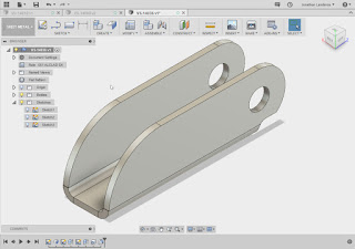
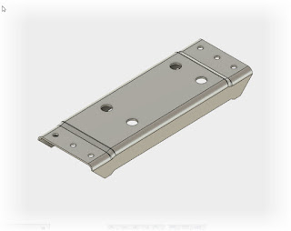
My first Fusion 360 sheet metal part
All I've had is a couple of evenings to create a few simple sheet metal parts.  They're no more than a couple of brackets, but they're also enough for me to start getting acquainted with the tools, even if it's sill a quick introduction.

But what I was able to do was to get a bit of an impression of how Fusion 360 works, and figure out where I need to learn a little more.

And when I say a "little more", I mean "a lot" more.

I've used sheet metal in Inventor on and off for around 17 years now, so it goes without saying that I approached Fusion from the perspective of using it like it was Inventor.

So I'll just cop to the fact that I can't help but compare it to Inventor.

What is the the kids say these days?  "Sorry.  Not sorry."

And while Inventor was similar to Fusion 360 in many ways, it was very different in others.

Here are just a few I've noticed so far.

Sheet Metal Rules

They're actually a lot like Inventor's sheet metal rules.  It's similar enough, that I could make the jump pretty easily.

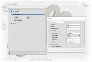
Fusion's Sheet Metal Rules.  I've created my own rule here.
I miss the thumbnail images that Inventor has in its sheet metal rules dialog, but I could navigate it pretty well based on the information provided by Fusion.

Bend tables and equations aren't in Fusion at this point, but even when they were available in Inventor, I never knew anyone who used them to generate flat patterns.

I'm sure there are that do use them, I just didn't encounter them in my travels.  This may be one of those "future update" items.

I was able to create a new sheet metal rule in a few minutes, all it takes is copying another, similar rule and changing it to meet my new requirements.

The Flange Tool

In Inventor, the Flange tool created flanges from existing faces, that's it.  if you wanted to create a C-channel in one step, you had to use "Contour Flange".  If you wanted a flat sheet metal face, you had to use the 'Face" tool.

Fusion 360 combines those three tools into one "Flange" tool.

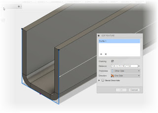
Using the Flange tool to create a channel

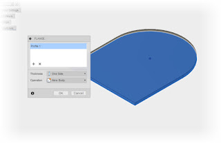
Using the Flange tool to create a sheet metal face.
The Flange tool creating a straight up flange.

Once I figured this out, I came to like it.  To me, it's a simple, easy to use approach, at least in my opinion.

After all, it's much harder to hit the wrong button when there's only one button!

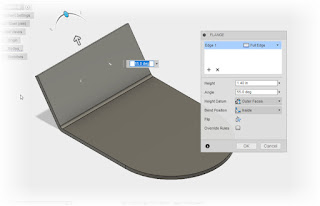
I also like how Fusion implemented the grips to change the flange height and angle.  It felt like a natural way to form the part.

After a few minutes of figuring out how it ticked, I liked the way they went with it!

Unfolding

Creating a flat patter from a folded part was easy for me.  Fusion 360 asks for a stationary face.  In other words, which face the part will use as its "anchor" to unfold around.

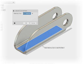
Selecting the stationary face for a flat pattern
Inventor did this as well, but to me, it didn't always seem obvious that you could provide Inventor with this information, especially to Inventor newcomers.  Although later releases of Inventor did address this with the "A" face tool.

In any, case, the functionality is essentially the same, just presented differently.

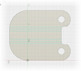
The flat patterned generated in Fusion 360


What Can be Unfolded?

See this part?  You're not unfolding this one! 
The rule of thumb I was taught for Inventor was if you could bend the part in a sheet metal brake, Inventor could unfold it.  Formed parts with a lot of deformation, or flanges around bends, aren't going to unfold in Fusion 360.

The same seems to hold true in Fusion 360, based on my few minutes of testing.  But I expected that, so there really aren't any surprises here.  

I just had to see if maybe, just maybe, there was  the computer aided equivalent of the Holy Grail in the unfolding tools!

In conclusion.

After what was, at most, two hours of seat time, I was able to generate some pretty simple sheet metal parts pretty easily.

There's some room for growth to be sure, but I'm sure improvements will be made in future updates.

The functionality that I've seen so far, I like!

And I do have to reiterate that I have very little time with Fusion 360 sheet metal, so it's even possible there may be functions I haven't even discovered yet!

So at this point, I'll enjoy, and continue to learn the functionality I have, and look forward to those updates in the future.

Sunday, March 05, 2017

The Amazon Web Service Outage of 2017

Earlier this week, Amazon Web Services suffered a service disruption.  For me personally, that meant disruption in Autodesk Fusion 360 (which I thankfully wasn't using at the time), and Fusion Lifecycle, which I was.  Fortunately, while Fusion Lifecycle was disrupted, it wasn't offline.

So, what happened?!?!

Several sites were affected.  My girlfriend sent me an instant message to let me know their CRM (Contact Resource Management) was down.  According to NPR, Gizmodo and Apple iCloud were affected.

The amazing, and perhaps disconcerting part of this is how easily the service was disrupted.  It seems that a technician was troubleshooting, and took off more servers than intended with a typographical error.

That's right, a typo, fat fingers as us techies call them, were the cause of the disruption.

Added to that, there didn't seem to enough redundancy, or possibly any, to absorb the lost servers while they were brought back online.

Now I'm no expert on Internet architecture. I imagine I know more than some, less than others.  I'm not going to prognosticate on what Amazon could have, and should have done, or should be doing.

There are plenty of people smarter than I who can do that better than I can.

But what I will say, is what I learned, relearned, and what I can do in the future.

What I learned and (relearned)

  • The cloud is a great tool, it's saved my class grades when I didn't print it out by mistake.  But the technology is new, and new technology is often developing systems, and developing systems can be prone to failure.  
  • As a whole, the cloud is pretty robust, but when it fails, it can fail spectacularly.  Many can be affected, and word can get out quick!
What can I do in the future


  • I can't make Autodesk, Amazon, or anyone else change their system, at least not directly.  But I've heard rumors that improved offline capabilities are on their way.  I hope they're true, and that after this outage, the efforts have been increased.  I'll be keeping my eyes out for that development! 
  • To this end, I'll be doing a better job of backing things up locally.  That's right, in a 180 degree turn, I'll be working in the cloud and backing up locally.  Just in case. 
I won't be abandoning the cloud, what I will be doing is approaching it more cautiously, and more diligently.  

In many ways, the cloud is a new frontier filled with pioneers, and pioneers must face the hazards of a new frontier to pave the way for others.  

For my part, I'll choose to stay on that frontier, but I will make sure I'm planning ahead! 

On into the brave new world!

photo credit: NPS Park Cultural Landscapes Program Chilkoot Trail via photopin (license)

Sunday, January 15, 2017

A360 to Share a Fusion 360 Model - I Got the Feedback I Needed In Minutes!

There are many examples of people who have used computer aided design programs like Fusion 360 to create models for replacement parts that can no longer be located.

It's a fantastic technology, one that in my personal opinion is still in it's early stages.

This is my experience with a knob on the stove in our home. Now, this isn't a story of how I created a model, had it 3D printed, and how incredible the end product is.

There are many of those stories.  And their success is well deserved. 

I'm just sharing a step in the journey as I learn about the process first hand.  I may follow through and find success!  Or I may find, for some reason, it's not worth pursuing any further. 

But carrying that dose of reality. Here is the first step in that journey, building and sharing the model. 

Building the Model - The Easy Part! 

Building the model was a process of measuring the knob.  That meant pulling out my trusty set of calipers and carefully measuring the knob.  I had to make sure that the dimensions, particularly where it mounted to the stove were correct.  


The process of modeling took only about two relaxed hours on Friday morning, which for me is a day off. That part was pretty easy. 

The stove knob modeled in Fusion 360.
But now I've finished my model and it's only about 9AM.  I'd like to share the model with her, but she's just started her day at work.  

So how do I share the model? 

How do I share the model quickly, easily, and effectively so I can get feedback as soon as possible?

My Answer - A360

In a previous post, I mentioned that Autodesk 360, or A360, mirrors your Fusion 360 projects.  Now was time to take advantage of that for collaboration to a fuller, if not completely full form. 

I opened the model in A360 and opened the file in the A360 viewer.  I clicked the share icon to start the sharing process. 

The knob in A360.  Notice the "Share" icon in the upper right.
After selecting "Share" the sharing options will show up.  


In my case, I made sure the file was shared.  Then I copied the link to my instant messaging program, and sent it to my girlfriend.

After a about 30 minutes, she had taken a look at the model in her internet browser, and had given me a few thoughts on what I had done.

First circle completed!

Thoughts on Collaboration

While very tech savvy, my girlfriend isn't a CAD operator.  But with just a link, she was able to view the model in all it's 3D glory.  I didn't have to take half a dozen screen grabs, and wait for an email.  Points to A360 for that.  The online view did all it needed to do, and it did it quickly, and efficiently. 

My total turnaround time was less than 3 hours from starting to build the model, to having my girlfriend's feedback. 

On another note...  If your aware of Autodesk's Live Review you might be wondering why I didn't use it. The answer for that is a simple matter of logistics.  With my girlfriend at work, I had to accommodate her schedule, which meant sending her a link that she could use at her convenience.  Sending a link was the best tool for this task. 

Next Steps?

The next thing to do is look into getting the part 3D printed.  The main question is will it be cost efficient.  There's no sense if the cost to make a new knob is 20% of the cost of a new stove.  

But that's what I'm trying to learn by going through this process.  

I'll keep you posted on this part of my journey!  You're learning along with me!   Or at least that's my hope! 

And if' you'd like to look at the Fusion 360 model yourself.  Here's a link!  Feel free to have a look.