Find us on Google+ Inventor Tales: Interoperabilty
Showing posts with label Interoperabilty. Show all posts

Sunday, August 28, 2016

Modifying an Non-Fusion 360 part in Fusion 360

Just a tick over a year ago, I tried an experiment to build a 3D model of the aileron horn Spanish BF-109.  Then I printed it in 3D to prove the concept.

The original part, and the 3D printed part, side by side


The model of the horn. 

And the concept was proven.

But in that experiment, I found that there was another challenge.

I had to measure the part by hand.  Naturally, that creates the opportunity for error.  And of course, I made an error.  I mis-measured one dimension, and the part was too tall.


Now, at home, I primarily use Fusion 360, simply because it's what I have access to on my personal laptop.

But that raised an interesting scenario to me.

What if you don't have access to the technology that created the software, but still need to make modifications to increase the manufacturability of the product, or perhaps there's feed back that needs to get back to the designers.

Well, here I found myself, wanting to make a few modifications to the aileron horn, but my Inventor installation is 20 miles away on my work computer.

It's time to see what Fusion 360 will do for me.  I can modify the solid, and I don't need access to the feature tree to do it.

I've brought the model into Fusion 360, but let's look at the mis-measured dimension I mentioned earlier.

I'm going to shorten the top flange, and rotate it a few degrees for good measure.

Let's start by right clicking and choosing the Move command.

Let's get moving!
Now comes the selection part.  For this operation, I'm going to choose the faces option.  I'll also choose my center of rotation as the tube supporting the flange.  Notice that you can also translate or rotate the triad, or snap it to existing geometry.

Now comes the selection of geometry to rotate.  That translates into selecting the faces you want to rotate. I'll choose the holes, and all the faces I wan to rotate.

Choosing the faces to rotate. 
And don't forget any back faces too!  Missing one can fail the operation!

Don't forget any back faces! 
Now comes the time to rotate and translate the part.  This can be done by selecting the appropriate translation arrow, or rotation radius for the operation, and dragging or typing in a value.

An example of rotating the flange
Now by dragging the grips, or typing a value, the flange position can be changed to exactly what is needed.

The part after accepting the change.
So here's how Fusion 360 helped me out.  I was able to make the modifications I wanted when I didn't have access to the authoring program, in this case Autodesk Inventor.

The part before, and the part after.  

But the file could have just as easily been from one of several types.  So there are certainly more options to explore!


Sunday, November 15, 2015

For a Good Finish - Flipping a Flat Pattern Base Face in Inventor

Laser mills can be fascinating machines to watch.  Even thought they've been around for years, watching them still feels like a little bit of science fiction.

Just watch this video from Wikipedia and try not to imagine something sci fi!


But no matter how sophisticated the tool, there are always "tricks of the trade" to get a little more out of the tool. 

One thing I've learned is the care of keeping the "good side up".  

The material in a laser mill rests on a grid of pointed steel plates I've taken to calling the "bed of nails".  

Looking at the image below, you an see pretty easily how that could mark up a surface you'd be hoping to keep free from marks.  

The laser mill bed. Certainly not the place to get a good night's sleep.
Because of that, you may have guessed it, it becomes important to keep the "good side up".  This keeps the visible side of the sheet metal off the "bed of nails", making sure it's got a clean finish. 

In Inventor, this means making sure that when clicking the flat pattern icon, the face that Inventor shows you is the "up" side.  

But how to you make sure the good side is out?

The obvious way, is to choose the "A" side right away, either by using the "A Side" tool, or by selecting that as your face when you create the flat pattern. 

But what if you need to change it after the fact?  In spite of the best efforts of the best designer, it's always possible one flat pattern is going to be reversed. 

An easy way to fix an incorrectly oriented flat pattern is just to delete it and replace it.  This might work great if a drawing using the flat pattern hasn't been created yet, but what if it has?

If a flat pattern view is created, deleting the flat pattern means recreating the view in the drawing. 

This is a fairly simple flat pattern.
But do you want to recreate it if you don't have to?


In other words?  It means more work. 

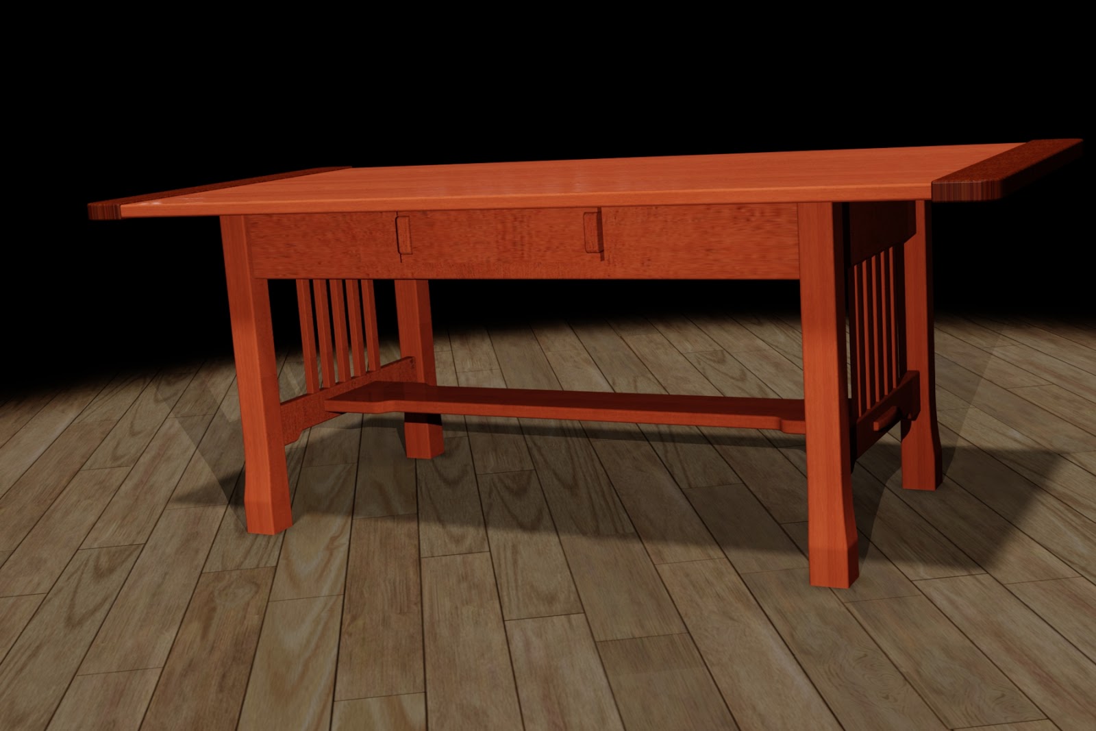
So here's an alternative that I think you might like. I'll flip the "A" side of the sample below.  I've colored one face red to make the change a little easier to follow.

Getting started with a sample part.

First, while in your sheet metal part's flat pattern, right click on the flat pattern icon and choose Edit Flat Pattern Definition.  

Accessing the flat pattern definition.

Now, a dialog box appears that allows the option to change, create, and save orientations if you'd like. In this case, it's the Flip option under the Base Face section we're interested in. 


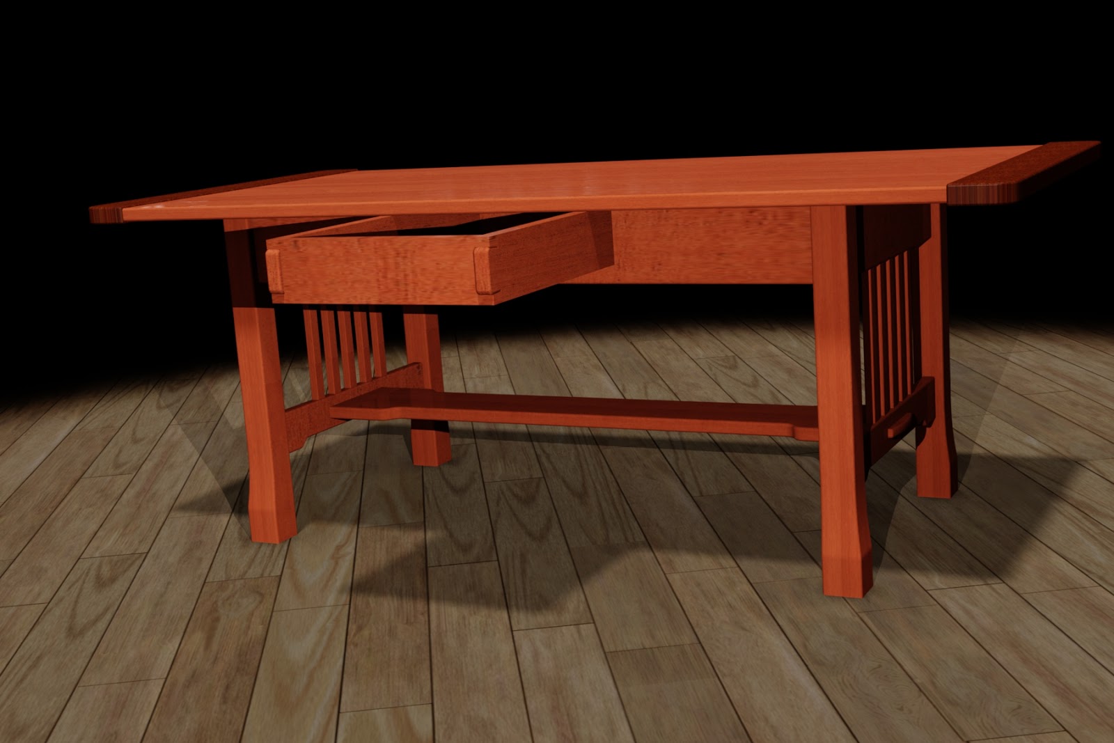
Clicking this face flips the sheet metal face over like a pancake on the griddle.  In the flat pattern sample used here, the silver face is now visible. 

The face is flipped over

Now, switching to the drawing, the flat pattern also shows the silver side, Careful inspection will also show that the bend directions have all changed too! (Careful, the view is rotated 180 degrees).


The flipped, can completed, view.
You may noticed that the dimensions need some rearranging, but at least speaking for myself, I'd rather rearrange annotations than recreate a set of annotations.  In other words, this is a small trade off for the time saved when facing recreating entire views. 

So if you're facing flipping a sheet metal pattern over for any reason at all, I suggest considering flipping the base face.  It can be a real time saver. 

Thursday, June 27, 2013

Released into the "Wild" Autodesk Fusion 360 is Here!

“Fusion will be the final way out for the future.”
Shen Wenquan

Earlier this week, Autodesk announced Autodesk Fusion 360, a cloud based mechanical design tool.

So what does this exactly mean? 

Instead of a heavy 3D modeller sitting on top of your workstation, now you're operating on the cloud. 

The files are stored in the cloud.  In that ethereal world of 1's and 0's, designs are shared, collaborated upon, and versions are tracked, the whole time the design is being created, or "ideated",to use the popular buzzword

In this respect, it reminds me a bit of how I've been storing documents on Google Drive for years.

There's also a nice dashboard where projects can be managed with the design team of other Fusion 360 users.  Combining a bit of a social media site with data storage for design files.

Files can be accessed where ever you have access to your Autodesk Fusion Account, and since the files are on the cloud, they're also accessible, as well as continuously being backed up. 
No more opening your laptop to realize you forgot to copy a file from the server! 

Just yesterday I signed up for my Fusion 360 account.  I'll shortly start creating simple parts, trying some collaboration, and quite simply, kicking the tires on a new way of approaching design.

Here's my new dashboard.  A clean slate ready to get started

So in many ways, I'm still learning about Fusion 360, and I expect to continue learning.  I'm hacking my way with my virtual machete, bullwhip on my hip and fedora on my head, trying to blaze my own new trail into new territory.

I'll be sure to let you know what I find!


And if you're interested in taking a look at Autodesk Fusion 360 yourself, click here to get started!

For more information on Fusion 360, check out the overview below from the Autodesk Fusion 360 team! 


There is also an interesting interview with Autodesk CEO Carl Bass with Bloomberg, where he discusses the cloud, Fusion 360, and even the U.S. Patent System.


Sunday, March 10, 2013

Righting the World - Changing Import Settings for Autodesk Showcase

“In the time of my life, I need more time just to make things right.”

Sometimes a that clanking sound I hear is a wrench hitting hitting my proverbial works. 

And when importing files into Autodesk Showcase from another system, the import orientation (or disorientation), can be that wrench. 

Take this for example.  Sometimes a file imports, and instead of being right side up, it's completely on its side.


Blast it! 
The easy way to fix it is to use the Transform Handles in Autodesk Showcase to correct the problem.  But what if there are positional alternatives that need to be preserved?  Rotating with Transform handles can sometimes mean rebuilding the alternatives.


Rotating with Transform Handles is sometimes an option
Fortunately, there is another option when importing files.

First, when in Showcase, choose File>Import>Import Files


Preparing to import a file.
When the import dialog box opens, choose the "Settings" button.

Choosing the import settings

Once the import settings dialog box appears, the setting for "Original up axis" can be seen.  This is where I can tell Showcase "which way is up". 

Note that you can also see the "Import Representations" checkbox in this dialog box.  So Inventor representations can be imported in as well.

Changing the orientation

If I take a quick look at the file in Inventor, I can see the +Z-axis corresponds to the top of the table.


Seeing this, I'll choose the +Z radio button, and import the files.

Selecting the +Z option
The file will import, and the orientation will correspond to the "up axis" I selected.


Oriented with representations created as alternatives!

And if you're looking for the usual video that accompanies my blog posts, here you go!


Tuesday, March 05, 2013

Bring Autodesk Inventor's Positional Representation into Autodesk Showcase

“Affliction is enamoured of thy parts, and thou art wedded to calamity.”
William Shakespeare

When designing, there are times that alternate positions for components must be shown to ensure the design will perform as intended. 

This might be an arm extended and retracted, or a door or drawer opened, and closed.

There are also times those alternate positions need to be shown in a rendered view to properly convey the design intent outside of the design product. 

When using Autodesk Inventor, Positional Representations are used to accomplish this task in design.  For example, here I'm showing a coffee table with  drawer open, and drawer closed positional representation. (For instructions on how to create a positional representation, check out my previous post here)

A positional representation showing a drawer closed


Autodesk Showcase uses Alternatives to create alternate positions for the renderings.  Here is the same table shown with alternatives in Showcase

The model is imported and ready with the drawer closed
The alternative with the drawer open is already created.
While each product can work independently and create their own distinct representations of the components, there's no reason to recreate work twice.  What if what I want to do is reuse the representations in Inventor, and use them to create alternatives for Showcase?

Fortunately, Inventor and Showcase has a "Suite Workflow" that allows the representations created in Inventor, to create alternatives in Showcase.

I'm going to begin with  my coffee table open in inventor, then I'll  click on the Application Icon (The big "I"), I choose the "Suite Workflows", then choose, "Showcase Realistic Presentation".

Starting the representation


A dialog box appears that describes what this setting will do.  I'm going to choose the "Settings" button to make changes to how the model appears on import.

Selecting the settings for import
Here the settings for import can be set, such as the conversion settings (the density of the facets making up the Showcase models), Visual Style, and Lighting Style can be set.  Most of these can also be set in the Showcase scene, so I take defaults for most with one exception.

I do like to set the "Environment... Plane Level" setting to "At bottom of the model".  While your settings may vary, this setting is works best for the models that I create.

Workflow Settings

Now I go ahead and click "Run".

Pulling the trigger and running!

The model will process, and will open in Showcase.  Both alternatives are created by the positional representations

Now all I have to do is apply the desired materials and lights in Showcase, and finish creating my model in Showcase. No recreation of the drawer open, or drawer closed.  Just use what Inventor provided to Showcase!

A quick rendering in Showcase with the drawer close
The same scene with the drawer open via the alternative.

And to see the steps in a video format, just take a look below!


Sunday, June 03, 2012

Simplfy... Simplify Me - Inventor Simplfication from Autodesk Labs


In my post last week, I talked about how you could remove features and voids using some of the new tools in Autodesk Inventor 2013


Now, while cruising about the internet, I find Inventor Simplification. Brought to us by the team at Autodesk Labs


Admittedly, this tool did come out back in April, but I only got to install and start driving it late last week.  


So what about it is so wonderful that it warrants a blog post? 

I was impressed by the workflow.  There are only four tools, all located on a "Simplfy" tab that's added to Inventor's ribbon.


y
Just for buttons!  That's it.


  Another plus, is the flow is pretty natural, at least in my humble opinion.  The basic steps are:

  • Select the components to be added to the simplification by picking, or using a filter for external parts

    • Inventor Simplify creates a View representation containing the parts selected

  • Export the parts to an Inventor part file that now contains the simplified geometry.  If desired, the exported geometry can be edited further by patching holes.  This removes additional detail, or even voids.

Optionally,  components can be reduced into "envelopes".  In other words, show the volume the components occupy, without showing the actual component.  Handy for removing that intellectual property you don't want to show!


Additionally, if components need to be removed from the simplification, the View Representation can be edited. This makes it a lot easier to make adjustments.


An example of a simplified component

As always, I've got a video where you can take a look at the process.  If, after seeing the video, you can't wait to get your hands on it, you can download it at the link here


Have thoughts or cool uses for Inventor Simplfication?  Throw out a comment.


On a more personal note.  I've tried removing the "bookend" slides from the video.  I'm looking for a little feed back on if the users out there would like them better "out" or "in".  Let me know! 

Sunday, May 20, 2012

Migrating Colors and Materials into Autodesk Inventor 2013

“A hard fall means a high bounce... if you're made of the right material.”

A new change in Autodesk Inventor 2013 is how materials and colors are handled.  Instead of being a part of the Styles and Standards libraries, like in previous versions of Inventor.  Now, they're stored in Appearance Libriares (for colors), and Material Libraries (for materials).

The location of the new libraries can be seen by looking at the project file.

The libraries as shown in the Project File
But what if there are old libraries that have been created over time?  We wouldn't want to throw them out and start over right.  So there has to be a way to migrate them, right?

Well, of course there is!  (or else I wouldn't have anything to blog about).

But how are the libraries migrated? 

It's fairly simple, once you know where to look, as I'm so fond of saying,

There are two places to access the Appearance and Materials Libraries.

The first is from the quick access toolbars.


The second, off the Tools Ribbon on the Materials and Appearance Panel.

On the Tools Ribbon
Choosing either icon will bring up the browser for that particular library.  

Migrating to both the Material and Appearance Libraries is a matter of clicking on the "gear" icon in the lower left hand selecting "Migrate Inventor Styles".

The dialog for Materials.  The Appearance dialog is nearly identical.

The source (the library to be migrated) is selected, followed by the destination library.

However, there are two destinations to send your migrated folder, one is to create a new library, the other, select an existing library.

So what to do?

There's two theories.  One is to migrate your old libraries to a newly created one, and remove the old Inventor libraries.  This makes sure you have "one truth" for those materials.

The other, is to merge them into the existing library.  The important, custom materials will be there.

Which did I choose?  Personally I used "Create New Library.  For me, it was a little easier to have that "one version" of the truth.  I can remove one library later if I don't want it.


Hit okay, and the migration begins.

Soon, the migrated Material Library is complete.

The best part now, migrating the Color Library to the Appearance Library.  Why is it so good?  It's basically the same steps!  If you've done the Material Library, you can do the Appearance Library.

Naturally, it wouldn't be a blog post without a video.  So here we go!


Do you have input on how you might have migrated your own libraries!  Throw a comment below!

P.S. If you're interested in how to migrate Dimension Styles, Sheet Metal Styles, etc.  Check out last week's blog here! 

Wednesday, December 21, 2011

Windows User Account Control - The Ghost of Securities Past

“If everything seems under control, you're just not going fast enough.”
 Mario Andretti

If you've been following my blog, you may have noticed that I've slacked a bit on posting.  It's been a busy week of a business trip to Mexico for a day, a lot of demo prepping and installations as the year comes to a close, and a short vacation to Mammoth to catch my breath from it all.

But that doesn't mean that the lessons haven't stopped.

A couple of weeks ago, I ran into an issue caused by a demon I thought had finally gone a way.

User Account Control (UAC).  Found in Windows Vista and Windows 7, it helps secure your system against unauthorized changes. 

It's quite effective.  As a matter of fact, it's so effective, it can prevent programs you need to change your system from doing so, rendering that program unable to do important operations.

Like install, for example.

In recent years and software releases, the issue has gone away as Microsoft, and the programs that installed on it, have learned to coexist much more efficiently.

But recently, that little monster reared up again with an installation of Autodesk Simulation Multiphysics 2012 Service Pack 1 on Windows 7.

I received a tech call where a user was getting a cryptic MDAC error.  It was pretty cryptic, and definitely a little frightening. 

Here's the error, but what does it mean?
It didn't indicate what the error was at all, but once we had eliminated things like the user having appropriate privileges, virus scanners were off, etc.  I remembered one thing.

"UAC used to cause wacky things like this...."

So we went into the control panel, and turned off UAC. 

In Windows 7, pull the slider to the bottom!
Sure enough.  Once that was done, the install went through seamlessly.

Gone away the issues of UAC?  Not just yet!  If it's up to me, I turn if off.  If you ask what I think about you running it?  See the part where I turned it off.

Does that mean that you're going to encounter issues if you leave it on?  Not necessarily, but keep in mind that it can still cause issues (as experience taught me).

So if a program or service pack won't install.  Or if a program doesn't start, it's worth taking a look at UAC.  IF at all possible, shut if off, if only to eliminate it as a culprit.

It can save a headache or two!

And if you want more info on turning off UAC, there's a KETIV Tech Tip!

Note that the tip is for Windows Vista, but Windows 7 is very similar.


Sunday, January 23, 2011

FlexNET Publisher - A License to Network

“Vote: The only commodity that is peddleable without a license”
 Mark Twain

Today's blog is rather short, for a couple of reasons.

First, as some of you who follow my Twitter feed have noticed, this weekend was another snowboarding escape to Mammoth Mountain in the Sierra Nevada Mountains

Me with the giant snowman.  He's celebrating a world record breaking 209" of snow in December 2010


Second are some last minute preparations for the first FlexNET class that I've done in quite some time.

Some of you may know this screen
So for this brief blog post, I thought I'd give a short description of what this FlexNET thing is, and what it's doing with your software. 

FlexNET Publisher is a licensing utility created by Flexera Software.  This utility allows you to float licenses of your Autodesk software across multiple machines, even allowing you to install your software on more machines than you actually have licenses for. 

I'm sure somebody out there in the cyberverse is scratching their head.  After all, didn't I just state something that implies, at face value, that you can have run more seats of software than you actually have licenses for.

This is where FlexNET Publisher comes in.  FlexNET Publisher is a utility that is installed on a central computer (referred to as a license server moving forward).  

This server takes your network licenses and floats them among the machines you've installed software on.

For example:

You have 10 licenses of AutoCAD  software, floating on a network controlled by FlexNET Publisher installed on a central licensing server.  But you've installed AutoCAD on 20 machines, how does that work?

The first 10 users to start AutoCAD will get the licenses.  The 11th person to request the license gets a message indicating that the licenses are in use, and they have to wait for a license to free up.  Once one of the licenses is free, they can go ahead and grab that license.

That's how you can install AutoCAD on several machines, but keep yourself from using more licenses than you have.

It's like checking out books from the library.  Once all the books are checked out, the next person who wants that book, has to wait for someone to bring it back.

In a nutshell, that's what a network license is doing.

Of course this is high level, there are nuances, tricks, and things to watch out for, like in any system. 

But if you want to centralize your license management by having the licenses reside on a central server (or servers, but I won't go into distributed systems here), a network license may be something to consider.

And on one last note.  FlexNET manages licenses for many of the Autodesk softwares, but also for other vendors too.  If you've worked in an engineering department of one form or another, you may have used it, and never even realized it! 

That's it for this post.  But leave a comment if you want me to create some blog posts on network licensing in the future.  I'm happy to provide what I can. 

Happy Inventing!

Sunday, August 15, 2010

Yielding to Logic - Extracting Drawing Scale with iLogic

“The logic of words should yield to the logic of realities.”
Louis D. Brandeis

Just this Friday, I was posed what I thought was an easy, five minute, question.  "How do I place the view scale into the title block?"

My inside voice said, Pffft!  No problem!  After all, there's a spot right there for it in the title block already!

Scale is already there! 

So I go into my title block definition, and look for the iProperty that accesses the drawing scale. It should be a slam dunk.  All I have to do is choose the property that calls the scale.  But as I look, my stomach sinks.


Here they are.  All I have to do is choose one.  But wait?!?
It isn't there.  Scale isn't available.  I think I know why this is.  In many cases, the scale can easily vary from view to view, so which do you call? 

I puzzle over this a bit.  I bounce it off of Javier Chavez, one of my KETIV team members.  He confirms what my eyes see.  The scale isn't there.

So, now, as they say, it's time to execute 'Plan B'.  Which means, I have to develop a 'Plan B' to execute. 

Now I'm pacing about my little office, rubbing my chin, and annoying my coworkers with my heavy footfalls. 

After a few moments, I have 'Plan B'.... iLogic!

iLogic to the rescue!


So I create a new iLogic rule, and enter the following code below (with comments):

'Forces update after rule runs
iLogicVb.UpdateWhenDone = True
'Extracts scale from 'View 1' on drawing sheet' to a field named SCALE
SCALE = ActiveSheet.View("VIEW1").Scale
 'Writes scale to a custom iProperty named SCALE
iProperties.Value("Custom", "SCALE") = SCALE

Here's the rule in context of the iLogic editor.


In short, the code extracts the scale of the first drawing view via the API, and writes it to a custom property.  With the scale written to a custom property, NOW I have something I can extract for the Title block!

SCALE custom iProperty


With this field added to the title block, I'm in business.

The custom iProperty

With that being done, is the rule perfect?  Frankly, no.  I have work left to do.

This is what's still on my to do list.

1) My triggers don't update completely every time.  Just like Rule #2 of Zombieland, I have to 'Double Tap' the update button once in a while.  I want to go over it and make sure it updates consistently.

Still have to work on the triggers some more


2) The view has to be called 'VIEW1'.  If it's not, or if you delete the first view and place another (now called VIEW2) the rule will bark about not having 'VIEW1'.  So there's a little work to be done to remedy that.

But I think the backbone of the routine is solid, and I'm willing to take a little time to revel in a small victory, if only for a few seconds.  I don't consider myself one of the iLogic 'gunslingers' so sometimes you have to 'Enjoy the Little Things'.

Which by the way, is Rule #32 of Zombieland!  :-)

As I learn more, and improve the rule, I'll post updates!

Happy Inventing!

P.S.  It's back.  Autodesk Manufacturing Academy is back, hosted by KETIV in Cerritos and Oregon.  Come see us in October!   And check out the videos from last years session HERE!

***UPDATE 20-March-2012 ***

After some hunting around, and help from a friend or two, it looks like teh direct update can't be triggered right when the view scale changes.  But if an event trigger is set to run "Before Save Document".  The rule scale will update when you save.  I tried it in Inventor 2012, and it works!

Here's the ticket!