Find us on Google+ November 2009 ~ Inventor Tales

Monday, November 30, 2009

Defining Inventor Parameters. Making Inventor Remember, so You Don't Have to!


If you want to understand today, you have to search yesterday. ~Pearl Buck


Every once in a while, I run into one of those things that I've done so many times, that I take it for granted. But that's when I realize my assumption is really keeping a secret that shouldn't be kept.

This is one of those cases.

I've been working on and off (since I was on vacation, you could say more 'off') on my night stand for what is a future wood shop project. Actually, it's probably more like a distant future wood shop project!

At least give me a little credit. I've already built one night stand!


(click to enlarge)

If you've worked much in wood, the three dimensions that you can't avoid are 'Length', 'Width', and Thickness. In this project, at least one thing is certain. There's a lot of things that are related to one of these major dimensions.

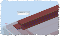
Take, for example, the back panel shown here. I've colored it brown to make it stick out. It's compose of a panel, enclosed in a frame of rails (the horizontal pieces), and stiles (the vertical pieces).

And before you wordsmiths start pointing out that I've misspelled 'stile'. In word working, the 'stile' is the correct spelling for this part.

'Style' is what the finished night stand has, as in 'Wow, that night stand has some style!"


(click to enlarge)

The panel slides into slots cut into the rails and stiles.


(click to enlarge)

The thickness of the rails and stiles are all .750 inches. I want the slot to be .250, or more precisely, 1/3 of the thickness of the rails and stiles that frame it.

Of course I could just build the slot, and type in '.250' to create the slot. After all, the math is pretty easy, right?

But what if the thickness changes? It's possible. Then I have to make sure that I remember to change the thickness of the slot to respect the '1/3rd rule' I've decided on.

Here's an easier way to remember that. Make Inventor do it!

When I built the part, I created parameters for Length, Width, and Thickness, among others. Here we're just going to focus on thickness, which is set to .750 inches

(click to enlarge)

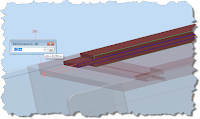
Editing the sketch that defines the slot, I can see that I've have it set to .250 inches, but there's no intelligence to it, I've just done math metally, and typed in the value.


(click to enlarge)

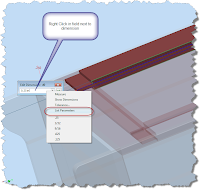
But, if I right click in the white field where the dimension is located, I have an option to 'List Parameters'.

(click to enlarge)

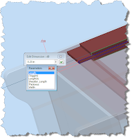
If I choose this option, Inventor will show all the parameters that I've renamed from their default d(X) values.

(click to enlarge)

I can now just select the parameter I want to build from, in this case 'Thickness', divide by '3', and I have that intelligence built in now.


(click to enlarge)

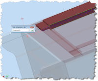
Should my value change for any reason, the slot thickness will update to reflect that. Here I've changed the Thickness to 1.5 inches (way to thick in reality, but it shows the update nicely). You can see that the slot thickness has changed appropriately.


(click to enlarge)

There you go! A little way to capture your design intent, and maybe for that, 'I must have forgotten to change THAT!' moment

Happy Inventing!


Sunday, November 29, 2009

Working with files in Showcase. The Beauty of Simplicity.


“Our life is frittered away by detail ... simplify, simplify.” Henry David Thoreau

Since my last blog post, I've found myself working with Showcase lately on some projects. During this time, I've found myself trying to answer the age old question: How much detail is enough?

In Inventor, my answer has always been: 'Exactly as much as is needed to build the part, and not one bit more'.

When I say this, my goal here is the perfect point where there is enough detail to remove any ambiguity in the design intent, but not so much detail that you spend a bunch of extra time building unnecessary features into a model.

For example, do you REALLY need to put .010 radius fillets to show that you've broken the sharp edges, or will a note do the job just fine? Likely, a note is sufficient in most cases (although I'm sure there are exceptions).

I can't share the particular components I was working on in this case (sorry, I promised the guys who own the files), but imaging an assembly that requires a certain amount of detail to be manufactured correctly, number of parts, detail of parts etc.

But when I imported it into Showcase, the performance takes an immediate turn Southward. Just importing it took forever (like an hour), and manipulated it was painful.

So, what to do? When it comes right down to it, I didn't need to see that much detail in Showcase, after all, what is the end game for Showcase? A good looking rendering.

So instead of using the assembly, we created a single component that had what I'll call the 'macro details'. Everything that you'd need to see to make a good Showcase rendering, but eliminating the small details like screws and internal components, that will never be seen anyway.

Sure, this took a little bit of up front work, but think of it like building a fixture for a long run of parts in the shop. The time spent up front will save a lot more time, money, and heartache, than it costs you.

Sure enough, in my case, the import took much less time (on the order of a few minutes), and was much easier to manipulate than the large assembly.

Ultimately, it saved me time, and of course headaches. And I can definitely use a few less headaches!

Sunday, November 22, 2009

Where to Put that Widget? Bill of Materials Organization


“The secret of all victory lies in the organization of the non-obvious.”

Marcus Aurelius - Roman Emperor


Over the weekend, I was working on a night stand for a future wood shop project (all I have to do is get the tools for the shop!).

During the ongoing design, I ran into an interesting challenge I hadn't really put too much thought into previously.

The table top is an assembly of components, in this case, four boards. The lower table on the other hand, is a separate assembly comprised of several components and subassemblies.

(click to enlarge)

Joining the two, are four plates of metal called 'desktop fasteners' (click here for a picture). Essentially you screw into the end table from one side, and the table top from the other, joining the two components.

The first issue I had to resolve was the lack of a CAD model. I couldn't find one. Given the simplicity of thet part. I modeled my own, and put it into Autodesk Vault. Now I'll have it for all time. So long as I follow proper backup practices, of course!


(click to enlarge)

But my next issue was how to organize it? I thought about putting it into the lower table assemlby, but it isn't really a part of that, after all, what if I choose to put a different table top on it, and decide to fasten it in a different way?

Hey, anything is possible. Plus I want to keep flexibility in mind, right?

The same goes for the table top. What if I use the same subassembly elsewhere, with a different fastening technique? I don't think it's likely, but experience has taught me that 'not likely to happen' can be very different from 'not going to happen'.

Looking at that, I took the 'sleep on it approach'.

For once, sleeping on it was the right thing to do.

I woke up in the morning, and the answer seemed clear to me, even before coffee.

Why does it have to belong to either assembly? Why not put it at the top level, or general assembly?

I couldn't think of a reason why not. After all, this means that both the lower table and table top keep the flexibility they need, and the overall design intent is kept.

(click to enlarge)

I think to myself as I rub the sleep from my eyes. 'That'll work!"

So that's how the night stand goes together. Since the desktop fasteners are actually sold with the two screws, they become a subassembly of the plate and screws, and they're placed at the top level.

(click to enlarge)


Done! Whammo. For the way I wanted to organize things, it really does work!

Wednesday, November 18, 2009

But it didn't do that Yesterday! The Laptop to Brick Conversion Utility


1 definition

Bricked refers to any piece of technology which is unable to operate due to bad software. This could be your iPhone, Tivo, PSP, Xbox, or a variety of any other devices. Often times this occurs because you tried to upgrade the firmware to something that didn't come from the manufacturer.

Bricked - Also known as what happened to Jon's laptop Tuesday morning. I went to start it and nothing. It just sat there at the black bios screen, the hard drive spun hopefully, and then silence.

In the blackness of a bios screen, nobody can hear you scream... or curse.

Just what I wanted for the holidays! A laptop shaped paperweight! The USB ports aren't even powered, so I can't even charge my phone. This totally eliminates the possibility for me to make sarcastic jokes about my ultra expensive phone charger!


Is this the final destination for my laptop?

After trying it a few times hoping 'it'll be different this time', I give up. I get it back to the office in preparation for shipping to the 'elves of laptop repair'. I get a loaner machine for the time being.

Fortunately, I have most of the system backed up. So while I may lose some data, I'll still have to most critical data. Thank goodness for those backups! Still, I'll have to configure several things to get the loaner functional.

So this morning, we walk in, and decide to try repairing Windows, taking the 'we can't make it any worse' methodology of computer repair and diagnostics.

I hit the start button and all of a sudden, there's a merry whirring of a hard drive, and the Windows Vista icon. It's booting! It's been magically healed and raised from the dead!


It's ahhhlive!

How this happened, I don't know, I'm not sure, and I'm not arguing. I'm currently finishing up a check disk and defrag of the system, not to mention some much needed file maintenance.

Oh, and make sure to backup the remaining files too!

Go figure. I've never seen a system 'unbrick'.

Sunday, November 15, 2009

Autodesk Vault, Project Arduinna, and Why Did I Do THAT?

“Perplexity is the beginning of knowledge.”

Kahlil Gibran


For a long time I've considered talking about how I've set up Autodesk Vault that I've used for my side projects, and why I did what I did. I've avoided it, to be honest. if only because I had no idea where to start.

Finally, I've decided to start at the very beginning, and just branch out from there. This blog will talk about basic setup. Future blogs will go a little bit deeper. There's too much to talk about to squeeze in one entry.

Before getting started, there has to be a disclaimer. My Vault is set up this way because I decided to set it up this way. It's an example of one approach, not necessarily the only approach. I happen to prefer this method for my particular situation.

There will be others who will almost certainly disagree with my setup, and that's fine. I encourage everyone to look at the methods on their merits, and come to their own conclusions. The system is flexible, and different methods will have benefits and drawbacks.

Step 1: What is Autodesk Vault?

Autodesk Vault is a data management solution that provides check in/check out capability, version control, plus enhanced search and copy capabilities. It works with Autodesk solutions such as Inventor, AutoCAD Electrical, and AutoCAD Mechanical (among others). As well as Microsoft Office formats, pdf, jpgs, etc.

Step 2: Where did I apply it?

My 'personal project' was started in my days at a previous employer, and was named 'Arduinna' after the Celtic goddess of the forest.

Hey, I'm a geek, which means I must have a code name for this project. This is important lest I suffer a loss of 'geek cred'.

It started back when I was taking woodworking classes at Cerritos College, and designed my class projects in Inventor.


An End Table Design Similar to one I built in Class
(click to enlarge)

Ultimately, I decided I needed to track the data, and since Autodesk made a software that did just that, I decided to make use of it.

Step 3: How did I decided to go about it?

With an endeavor like this, you don't go running off without planning, no matter how tempting it is. So I sat back for a moment, and thought, what do I want to do to start planning this out? Here's the two biggest criteria that went into my decision:

1) My woodworking projects will be broken up by classifications that I chose, such as casework (such as bookcases and dressers), tables, accessories (small boxes, and such), as well as standard components (such as clamps for fixtures and screws).

2) I want to share these freely across all projects. Many components (such as drawers) can be reused across multiple projects with little or no modification. I want to make sure I maintain the maximum flexiblity to allow for this.

Everything else, at least in my case, was secondary.

So, as I started to setup my Vault, I setup my folder structure to look like this.

Folder Structure
(click to enlarge)

You'll see my project file in the top level. This is the only project file running all of the Arduinna project.

(pause to let everyone think about that)

That's right, only one project file runs everything.

For those of us familiar with Inventor, you may be saying to yourself, 'But Jon, you don't have one project! Each table, bookcase, or knick knack is a project!'

You'd be right, of course, but this is the difference between a project, and a project file. The project file just tells Inventor what folders it uses to search for files. It only segregates projects if we set it up to do so (by using multiple projects).

Recall how I said I wanted maximum flexibility to share across my projects? Using one project file maximizes that flexibility. This is why I went that route. Using multiple project files makes this much harder to do, and means the user has to pay close attention to which project file they're using.

I like simple. And if I only have one option to choose from, my choices are easy.

There is a draw back to this single project approach. By using this method, it's strongly advised I use unique file names. In my case, I'm perfectly fine with that. As a matter of fact, I enforced it. So for me, it wasn't much of a drawback.


Enforced Unique File Names in Vault Explorer
(click to enlarge)

With that, my stage was set to get Project Arduinna off and running. Folder structure, and unique filenames set into place.

Next time, I'll talk a little more about how I set things up.

Happy Inventing as we start rolling into the holidays!

Wednesday, November 11, 2009

Chasing Electrons and the Rockwell Automation Show

“Five years ago, we thought of the Web as a new medium, not a new economy.”

Clement Mok


Today was 'tradeshow day' for me. I spent all day at the Rockwell Automation Fair.

I worked the booth, and did some presentations on AutoCAD Electrical, which while an amazing program, not really my strongest suit. But don't get me wrong, I did get to show a little Inventor and Showcase too!

Needless to say the show was amazing though. Everyone from Rockwell Automation themselves, to FIRST (of FIRST Robotics Competion Fame) was there.

The attendees were all very excited about their technology, and everyone had a lot to share.

Plus I got to work with a lot of great people again in the Autodesk Booth, so even while working hard, we had the comradery of working with a great team.

The show was so good, I didn't even get time to walk the show and see some of the interesting things for myself yet.

But there's always tomorrow. I'll be there with my trusty Blackberry phone in hand, taking pictures of something interesting I'm sure!

Here's a couple of pictures until then!


At the booth. Just before showtime
(click to enlarge)


There were a LOT of people there.
(click to enlarge)

Derrick Smith of Autodesk getting ready to go on
(click to enlarge)


Derrick Smith, the Great Showman!
(click to enlarge)

Monday, November 09, 2009


“To write what is worth publishing, to find honest people to publish it, and get sensible people to read it, are the three great difficulties in being an author.”

Charles Caleb Colton


Well, this already sizing up to be pretty crazy, so I'm going to keep this blog entry simple. As a matter of fact, I'm going to take advantage of some previous work that's come full circle.

A while ago I had an article submitted to AUGI AEC EDGE and it was accepted!


Needless to say, I'm both excited an honored. It's really beyond words.

Click HERE for the magazine. The article ison page 46. Enjoy! And thanks again to AUGI AEC EDGE for the honor!


I'll be at the Rockwell Automation Fair in Anaheim Wednesday and Thursday. Since this show's a first for me, I'm going to see what interesting things are there.

Swing by the Autodesk booth and say hi if you're in the area. I'm hoping that me and my trusty Blackberry camera can get some good pictures!

Monday, November 02, 2009

Making a rendering 'Pop'. Normal maps in Showcase.

Indiana: Meet me at Omar's. Be ready for me. I'm going after that truck. Sallah: How? Indiana: I don't know, I'm making this up as I go.

Indiana Jones (Harrison Ford), and Sallah (John Rhys Davies) in Raiders fo the Lost Ark.

Since Autodesk Manufacturing Academy, I've been working on some recordings, which have been fun, but time consuming. I find that you're never done, you just have to move on! I'm hoping to get a few up on the blog, but I've been head down quite a bit lately!

As part of my recordings, I've been creating renderings in Showcase to add a little 'artistic flair' to them. As always, there's another challenge to overcome.

I've learned, both from others, and through my own experience, that the accuracy a computer brings can work against you in Showcase. In a rendering that's trying to create a realistic look and feel, the perfect, sharp angles the computer brings are a dead giveaway that this is a rendered model.

In this case, I was rendering a valve to make a nice little illustration for a Powerpoint slide. Nothing crazy, just something to look pretty, and catch the eye.

My first test was without a bump map. Sure enough, it's too perfect. It screams fake. At this point, I've learned enough to not be surprised when the first test comes out like this.

Definitely too perfect
(click to enlarge)

So what next?

In a previous post, I talked about using bump maps and normal maps to create the illusion of a wavy, or imperfect surface when the computer creates a perfect surface. Making the rendering look more realistic.

Showcase comes with maps inside of it, and you can find several through your favorite search engine at no charge. I've just typed 'Normal Map' into Google and searched the image area. I can usually find anything I want pretty quickly.

I decided that making the body of the valve look cast would do the trick. So I started by scanning the directory of normal maps to see what I could find.

There was no 'cast metal' map that I saw, and I didn't feel like hitting Google, even if I have had pretty good luck. It was late, and I was getting tired.

So now, I had to shed my engineers brain... You don't NEED a normal map that has a cast texture, you just need one that LOOKS like it's a cast texture.
Bingo. I allow myself a clever smile.

Hitting the normal map directory again, I try a couple of other maps, and finally find one that works.

Which is it? Leather. That's right, I used a leather texture to simulate cast metal.

(Click to enlarge)

If it's crazy, and it works, it's not crazy? Right?

So that's the big trick. Don't limit yourself to what should work. Look at what does work.

Because in the end, I got what I needed in about an hours work. I got a rendering that was good enough for my Powerpoint. I wasn't after something to manufacture to, just something to look good.


That'll do!
(click to enlarge)


One last trick, don't forget to play with the bump depth! Most of the time, I find it's too deep to make for a good rendering. I cut mine down to as low as .015, depending on the look . This one is pretty deep for me, .25. The default is about 1.0 usually, which is almost always too deep for my tastes.


In other news! Inventor Fusion Technology preview 2 is available on Autodesk Labs. I've been hoping to get a video on it, but no luck so far (much to my chagrin), but I'm hoping soon. I'm really liking where they're going with it so far.

And for the trivia buffs out there. 3D Connexion's Space Explorer put a cameo in G.I.Joe, the rise of Cobra. Now that the movie is hitting DVD, look for it when Baronness fires the missile in the Paris chase scene!


A Space Navigator in the G.I. Joe movie. I don't think controlling missiles was on the list of supported apps.
(click to enlarge)