Find us on Google+ October 2012 ~ Inventor Tales

Wednesday, October 31, 2012

Happy Halloween! & Flipping Normals in Autodesk Showcase!

“For me, writing something in the spirit of Halloween is like Mother Teresa writing on charity and sacrifice. It's just second nature to me.”
Danny Elfman

Today's blog is just a quick blog to say "Happy Halloween", and add a quick tip for Autodesk Showcase.  . 

Earlier today I downloaded a 3D model of a skull, in a STL format, from GrabCAD and imported it into Showcase.

But once the file imported.  It looked dark.  Almost like charcoal.   It was like the environment light was having no effect on it.


This skull shouldn't look this dark.  Somethings wrong (hint: check normals)

Experience has taught me what the cause of this is.  But not everyone may know the secret. 

The normals on the skull were all reversed. 

For those who may not  be as familiar with surface normals, each surface in Showcase has a positive and negative side, often referred positive and negative normals. 

While I can't say I know all technological reasons for the how the normals behave.  I do know one thing.  If the normals are backwards, which sometimes happens on imported models, the object won't light correctly.  That's what's going on with the skull.

So now that I know what's wrong, how do I fix it?

  • First, I went to the "Appearance" pull down menu and choose "Visual Styles Library". 

Bringing up the Visual Styles Library


  • Once the Visual Styles Library menu appears, expand the "Diagnostics" section.  This is where I find the option for "Normals".  Choosing this option, I see that the entire skull shades yellow.

Viewing the Normals
  • The yellow indicates that I'm looking at the negative side of the normal. This is why the skull isn't lighting correctly.  Showcase is also helping me out by telling me to Select an object and hit the "F8" key to flip the normals.

The yellow tells me I'm looking at the negative (back) side of the normal
  • I can hit the F8 key or I can select my objects and choose Edit>Reverse Normals from the pulldown menus.

Flipping the normals
  • The normals will flip, and the skull will turn blue.  This tells me I'm looking at the positive side of the normals now. 

The normals are flipped!

  • Now, all I have to do is select a new option from the visual styles (I chose the "Both Shadows and Ambient Shadows" option)


  • Now the skull looks a whole lot better, and I'm ready to complete the rendering.  Add a few shadows and lights, and I have something I can say "Happy Halloween with!

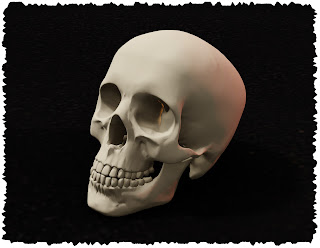
The skull with some materials and lighting

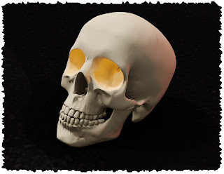
And with glowing eyes!
So that's it, a quick tip on flipping the normals on a model!  Have a great holiday everyone!


Sunday, October 28, 2012

Using Slice Graphics & Project Geometry in Autodesk Inventor

“The best thing since sliced bread”
Proverb

The Autodesk Manufacturing Academy concluded, I've taken this weekend to recover and catch up on things put off for AMA.

So I created a simple tip this weekend, but one I think is important.

Using Slice Graphics, and Project Geometry. 

Slice Graphics is a great tool for cases where you need to create a feature inside a part, and you can't easily see inside the part's cavity. 

Slice Graphics will give a virtual slice that cuts away a portion of the part so the inside can be seen.  Bear in mind this slice is virtual, like a section view in the 3D model.  It doesn't actually cut anything away.

All that is needed is an active 2D sketch.  When the sketch is active, right click (or hit 'F7' if you like hot keys, and you can toggle slice graphics on.  Repeating these steps will also turn it off.

The right click menu that toggles slice graphics on or off.

Now with the sketch active, Project Edges and Project Cut Edges show their value.

Project Edges will take an edge that isn't on your sketch plane, and project it onto the sketch plane so it can be referenced.  This can come in real handy when you need those edges to reference.

Project Cut Edges will project all the edges that have been cut by Slice Graphics.  I think this is a great tool when working inside of a cavity, like just like the part pictured above.

These tools are found on the Sketch Tab, when a sketch is active.

The Project Geometry, and Project Cut Edges tools.  Found on the Sketch Tab

And of course, here's a quick video on how these tools work. 

One last thing, when you create a feature, try Right Clicking, and choosing "Create Feature" to create the Revolve, Extrude,etc.  It opens up the appropriate tool, without turning off Slice Graphics.  It makes picking things a little easier!


Friday, October 26, 2012

All for Fun – Creating a 20 Sided Die

Death and the dice level all distinctions.
Samuel Foote

Many years ago, I friend asked me to create multi-sided die for a website he was creating.  You can still see the images on the banner of the website for DiceHouse Games here.

It was a tricky one to create.  It was a 20 sided die, a much used tool in role playing games like Dungeons and Dragons.

An Autodesk Showcase Rendering of the 20 sided die model

I also used it as an example in a blog post for using the “Change View Orientation”  tool inside of Autodesk Inventor drawings back in February 2012.  

***Edit 13-Nov-2012 : Added an embedded dwf of the 20 sided die***


A 3D dwf of the 20 sided die

*** End Edit***
Since that time I’ve started getting requests for how I built the die, as well as a location to download the actual *.ipt file.  

So here are the steps on how I built the 20 sided die!  


1. I found the definition of a Icosahedron (a 20 sided polygon) on Wikipedia.


The construction figure that started it all!

2. I created three sketches on the XY, YZ, and XZ origin planes in Inventor


The three rectangles on each plane to create the framework

 
3. Next, I used a 3D sketch to connect the vertices together, must like in the Wikipedia image.  If you’re wondering, this did take quite a bit of time. 


The process of creating the skeleton


4. This becomes the skeleton where I create several boundary patches.  The boundary patches create the surfaces of the die using the “sketch skeleton”.    This was also pretty laborious!

Boundary patches created close surface that could be stitched.


5. I then stitched the surface.  Since it’s “watertight” (completely sealed), it becomes a solid.

Stitching the surfaces make it a solid
6. Now it I had to add all the numbers (which were extrusions), and fillet the sharp corners. That’s it, I was done!


The completed die

So in conclusion, this was a satisfying little project took a little bit of research to figure out how to construct it.  Once I figured out the process, the steps weren’t difficult, but it did take time and patience to execute. 
 
Placing the 3D wires lines took a lot of time, and more than once I had to correct a line I misplaced.  The boundary patches took less time, but putting in all the numbers was an exercise in patience too.
 

So because of the requests, I’m uploading the file to a couple of sites for download.  However, before you go grabbing the file, I make only one request.
 

I spent several hours of a Saturday figuring this out.  All I ask is if you use this model, give me a nod and a little credit for the time I put into it.  
 

Now for the download sites!
 

The first is my Autodesk 360 site: Click here for Autodesk 360 download
 

If you use the GrabCAD file sharing website, you can also log in and get it here:  Click here for GrabCAD download


Sunday, October 21, 2012

Using the Transitional Constraint in Autodesk Inventor

Life is pleasant. Death is peaceful. It's the transition that's troublesome.
Isaac Asimov

This week proves to be another busy week as my second round presenting at the Autodesk Manufacturing Academy (this time in Cerritos, Ca.) comes around. 

That's right, even though I've been through it one time, I have to review my sessions, polish, an improve them.  Not to mention making sure I don't forget anything! 

But I did find time to create a quick video on an Autodesk Inventor tool that has been around forever, but seems to have drifted into obscurity as new features and functions have appeared over years of Inventor's evolution.

That tool is the Transition constraint.

The Transition constraint being applied to a "Cam and Follower"

Looking at the image above, it might make sense to use the Tangent constraint.  It would seem perfect to hole the cam and follower together. 

However, if this constraint is used, the tangency will only follow one face.  It won't transition to another face like the follower would in the real world.

This is where the appropriately named Transition constraint comes into play.  It can "see" the faces it need to transition to, and behave appropriately.

By using the Transition constraint.  Inventor will allow the follow to "follow" the cam correctly. 

Below is a video showing the behavior with the Tangent constraint, which isn't what I want, then I'll show the behavior with the Transition constraint, where we get to give the "big ol' nod of approval"! 

Thursday, October 18, 2012

A "Guest VIdeo" on Autodesk Showcase Materials

“The only thing more expensive than education is ignorance.”
Benjamin Franklin

Every once in a while I run across a resource that really captures my interest. 

Sometimes it's some sort of low pass by an airplane with a big piston engine, other times it's something silly like the "fainting goat" video YouTube.

But yesterday I came upon two fantastic Autodesk Showcase videos created by Marion Landry from Autodesk.

Marion created two outstanding videos on creating and manipulating materials in Autodesk Showcase.

I've already watched them once, and I picked up quite a few tricks I'll use in the future.  As a matter of fact, I'll watch them again, just because I know there are more tricks I'm going to pick up.

So here are the videos that Marion has graciously created for us.  Be sure to check out her channel here!

Creating Custom Materials Part 1


Creating Custom Materials Part 2


Sunday, October 14, 2012

A "Weekend Sebatical" Learning Practical Sheet Metal

“So never lose an opportunity of urging a practical beginning, however small, for it is wonderful how often in such matters the mustard-seed germinates and roots itself.”
Florence Nightingale

This week, a video blog post gets postponed.  Why?  I took a "weekend sabbatical" and took a two day class on hand building sheet metal aircraft parts. 

Why?  Because I miss getting my hands dirty, I love learning new things, and I wanted some practical knowledge that is only learned on the bench with real

I've seen the volunteer mechanics at Planes of Fame Air Museum working their craft, and been amazed by how easy the make it look.  All the while knowing it's not nearly that easy. 

So there I was, standing over a bench, looking at a pile of unformed aluminum parts,  countersinks, riveting guns, and pneumatic drill motors, wondering how I was going to "use those to turn that into something that looked like a simple aircraft structure".


My completed "practice project" is at the top.  I'm supposed to turn the pile of metal into something resembling a wing structure!
 I look around a second, and wonder if this is a good idea after all.  If I run now, no one will ever know.  I think for a second.

The first day I spent on a "practice part".  Just getting the hang of center-punching, drilling countersinking, and riveting.

This was my "practice" project.  All I did here was get used to the tools. It's partially completed here.

The first real life lesson I learned.  There's skill that goes into this.

Not that I thought it was a simple task before I tried it.  I knew it took skill, but it takes a lot of skill. All those mechanics I saw who made it look easy, are more than mechanics or technicians.  They're masters of their craft.

So how did that practice project go?
  • I got my holes drilled more or less in a straight line.  (Even center-punched, the drill walked a bit),
  • The countersinks came out good (redemption!)
  • The rivets were more or less correct.  (I need to be more diligent about preparation)
I did learn that it's no big deal to center-punch and drill out a rivet though! 

The next day, I had to actually make a basic wing box.  I learned how to use a wooden form the ribs from flat sheet.

Then it was more drilling, deburring, countersinking, and riveting.

Beginning the wing box.  Cleco pins temporarily hold it together
 And when I say a lot, I mean a lot!

I bucked flat rivets, universal (domed) rivets, I pulled pop rivets.

I drilled, bucked and drilled some more.

The partially assembly wing box with the top skin being attached.
 I learned a lot about how things like this are done.  I learned even more about how not to do it!

So in taking the time to do this project what did I learn that I can apply back to my "Computer Aided Design World"?

  • For every step I thought I knew about the process, there's some someone who has been around for twenty-some-odd years who knows all the steps I never heard of.
  • The term "sweat equity" is something executives use to describe hard work.  It's equivalent on the shop floor is "blood, sweat, and tears".  Building something with my own hands made me appreciate the value of the latter term.  The latter term is far more literal.
  • Speaking of  blood.  When a craftsman of this trade cuts himself, he'll clean the part before getting a Band-Aid, because he knows "blood is corrosive". 
  • Yes, I cut myself on the edge of an aluminum panel.  This doesn't really hurt, but bleeds quiet a bit. 
  • I also pinched my finger in a Cleco clamp.  This bleeds a lot less than the cut.  But hurts orders of magnitudes more. 
Note:  Close one of these on your finger, and it will hurt... a lot!
So in summary, it was a great experience for me.  If anything, I now know what it takes, and what I'd have to learn to be half the craftsman that those mechanics are.

This weekend gave me a new perspective on what it takes to build those designs that come so easily in the computer, and that it would be wise for me to never take that craftsman level of skill for granted.

So I guess the final question?  Will I continue, after spending an entire weekend building something that was mediocre at best and busting my knuckles (literally), would I take something like this on again?

Absolutely.  And why would I tackle this again?

Because however many mistakes I made, and however ugly that first part came out. 

I know I can do better, and I know I can learn more.  

And I learned to appreciate the craftsman that make it look so easy.


The completed project.  This is the "good" side.  Don't even look at the other!


Thursday, October 11, 2012

Outside the Box with Autodesk Inventor Publisher and Techsmith Camtasia Studio

“Hindsight explains the injury that foresight would have prevented”
~Unknown

For the second time, I've taken a video exported from Autodesk Inventor Publisher, and created a set of narrative instructions by editing the video in Camtasia Studio by Techsmith.

In this case, I created it as a sample for KETIV's Autodesk Manufacturing Academy in Oregon, which was yesterday, October 10th, 2012,  and California, coming up on October 25th, 2012.

Just like before, I started with an assembly.  This was a Dual Throttle Assembly provided by Datum3 Studios

The Dual Throttle Assembly created by Datum3

But just like any "2.0" version, this one is improved.  Sure, I had better tools in the sense that I had more current versions of both softwares (Inventor Publisher 2013 & Camtasia Studio 8.0), but I also have gotten better at creating them as well.
 
But putting aside the "fun and excitement" portion of the task, I realized there was a "real world" lesson hidden in my fun and games.

First, think outside the box.  I know I can be guilty of thinking about using my set of CAD tools to solve all my engineering and design problems.  Sometimes I fail to ;ook beyond what I can do with a little bit of creativity.

In this example, I wanted to use a voice-over.  Perhaps text or video instructions alone just won't cut it.  Perhaps this is going to be a file for use overseas.  With the help of a translator, a voice over could be created in several different languages for several different locales.


Not to mention the fact that I got to edit the video exported out of Inventor Publisher, edit it, and throw some cool transitions and effects.

That's where I took the video file from Inventor Publisher, imported it into Camtasia Studio, and started the editing process.  I threw in transitions, intro and outro slides, as well as watermarks, and credits!  

And as part of that "credit where credit is due" process, I can't thank Datum3 Studios for the use of their Dual Throttle Assembly..  This project would have been a lot tougher without their help!

Check the Dual Throttle assembly, and some of their other cool work, on their projects gallery here! 

So here's the result of a some spit and polish, and a few virtual blood, sweat, and tears.  I hope you enjoy, and maybe get a little inspired by a project I had a lot of fun creating.


AMA Oregon was great, by the way.  I only had time to take a few pictures off my smart phone, but here's a little of what went on!

KETIV's John Aiello presents to the crowd

Janna Spicer explains the benefits of the First Robotics Program

And everyone had a chance to mingle!


Sunday, October 07, 2012

Crunch Time Previews! - Linking between Autodesk Inventor and Autodesk Showcase

“My body felt extremely tired, ... I've got five or six gears in me, but I was crunching to get into second without a clutch. It was a tough day.”
Grant Hackett

Today is a much shorter post that usual, since most of my waking hours has been spent on creating my materials for KETIV's Autodesk Manufacturing Academy in Oregon on October 10th. 

So in this post, I'm afraid I don't have much that I can get into regarding new adventures or experiences, since..... well.  Look at that above statement on AMA!

But to that end, I've got a fantastic dataset graciously provided by Datum3 Studios.  You can check it out as the "Flight Controller Bases" section in the gallery HERE!  This data will be playing a big part in my "Digital User Manuals & Documentation" session.

The Throttle rendered in Autodesk Showcase
As part of the event, I've been busy creating supplemental videos that go along with the sessions, so this is what I'm sharing today.

In this video for AMA, I briefly show how Autodesk Inventor and Autodesk Showcase can link their data together, creating a loop of "collaborative development" where the rendering in Showcase can develop along side the engineering design developing in Inventor.

By utilizing this process, the aesthetics of a product can be developed and approved by the customer, all the while the engineering is going on in the background.  Both can develop simultaneously, instead of linearly as in the "traditional way".

Here's the video!  I hope you all enjoy this AMA preview!