Find us on Google+ July 2018 ~ Inventor Tales

Monday, July 30, 2018

Fusion 360 - Keyboard Shortcuts are here at Last!

Last week, Autodesk released a new update for Fusion 360, and while there's a few updates, the one that's getting the most attention is the addition of keyboard shortcuts.

Creating a shortcut

Now, if you'd like to setup your own custom shortcuts, you have the freedom to do it.  Just start a command from the pulldown menu, and click the "3 dots" on the far right of the toolbar.

Click the dots1

Now the Change Keyboard Shortcut dialog appears, and you can type in the shortcut to almost anything.  In this case, I chose to use "Shift+R" for a 3 point rectangle. Then hit OK, and you're ready to go

Changing the shortcut
You may have seen that I typed "almost anything" in the above paragraph.  There are some reserved shortcuts that can't be changed.  Among them are the standard Windows shortcuts, such as CTRL-S for save.  There are also shortcuts reserved by Fusion 360.

Man!  I'd love to make "S" a shortcut for "Create Sketch"!
And if you don't like any of the shortcuts you've created.  You can always restore to default! 

And finally, this wasn't the only enhancement to be introduced in this release, for the rest of them, follow this link here!


Wednesday, July 11, 2018

Dropping by the Pasadena 3D Printing Meetup

Some very cool 3D Printed Dice
It's said that we should learn from others mistakes, because we won't live long enough to make them all ourselves. 

It was in this spirit that I attended the Pasadena 3D Printing Meetup in Southern California.  Having picked up running a 3D printing machine recently, I've been trying to do what I can to learn as much as I possibly can.

And the group delivered.  There were several knowledgeable people who were happy, even excited to share their knowledge.  I got some great ideas on different materials to try. 

I was even able to share a little of my knowledge with new users.

This was followed by a presentation by Tracy and Tom Hazzard, who talked about the trials and tribulations of running a 3D printing business.  And they have experience, they run 3D Start Point.

Tom talked about building his own support structures, instead of letting the machine build them.  His goal was to reduce cleanup as much as possible.

There's some food for thought!

Probably the single best take away?  Tom and Tracy run a 3D printing podcast!  I've already looked at the first few episodes, and I'll be adding this to my regular podcast rotation!

It was well worth spending an evening with the group.  It's one I'd encourage you to attend, if you're in Southern California. 

And if you're not in Southern California, see if you can find a group in your area.  Meetup.com can be a great resource for that.

Here's a few more pictures from the group.  Enjoy!

And let's get out there and make some stuff!

A sample of PETG or PLA.  I can't remember which now.  I like the.
surface finish, and a lot of people recommend PETC

Another PLA/PETG sample.  I told myself I'd remember which was which.
I was wrong. 

A 3D printed tie.  It's printed in one piece and is wearable.
Tom Hazzard wore one for his presentation. 

A 3D printed bracelet printed by the Hazzards for their daughters wedding.
It was a wedding favor o the female guests.

A 3D printed bow tie.  This was printed as the wedding favors to the male guests.

The bow tie with support still attached.  This is the bow tie where
Tom Hazzard elected to keep the supports attached

Rope knots printed by Shorey Designs as part of a test.  The "fuzzy" rope on the
left has absorbed moisture form the atmosphere, the one on th eright was dried before printing.
That filament dryer I've heard about might be worth it. 


Thursday, July 05, 2018

Sharing a Short Lesson on Flared Tubes in Fusion 360

It's been a while since I've posted.  New projects and a different path of life have kept me away from working on "bloggable projects".

So I now share only the occasional post, and I hope that you find these posts helpful.

The other night, I was "doodling" in Fusion 360, and decided to model a "semi-rigid tube", similar to what one might find in an aircraft or some automotive applications.   It was good to get a little practice.


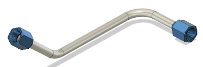
A typical 37 semi-rigid tube

And I found a couple of things that were worth documenting, at least for me.

Background on the Part.

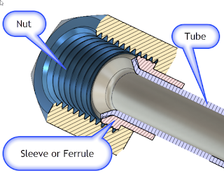
In real life, a semi-rigid tube of this type is composed of a seamless tube, typically made from aluminum, or stainless steel, although other materials are sometimes used.

The flare is backed by a sleeve or "ferrule".  This reinforces the flare.  This design also greatly reduces the possibility of "wiping" damage to the flare, since the nut doesn't turn against the flare itself.

So that's why the design is made the way it is!

The Part in Fusion 360   

The part isn't complex, it's just a path created using a couple of 2D sweeps.

The flares at the ends of the parts are revolutions.  Just like the paths creating the sweep, there's nothing earth shattering if you're familiar with the tools

One thing worth noting, I downloaded the flares and sleeves from McMaster Carr, using the tools built right into Fusion 360.  That's a nice feature that simplifies downloading and inserting standard parts.

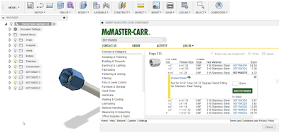
Inserting from McMaster Carr


I wrote about that tip here in a post a little ways back.  You can check out that post here.

And by the way, here's a link to the part.  Feel free to download it and take a look at it!


A Few Other Notes


  • McMaster-Carr actually didn't have the fitting I needed.  I wanted the fitting in aluminum, which does exist.  So I used a steel part and changed the material.  Yes.  In this case, I'd probably have to go elsewhere to purchase the part. In my case, Aircraft Spruce.  Sorry McMaster, I love you, but you didn't have what I needed in this case.


  • The parts from McMaster weren't modeled quite right.  There's some interference with the threads and the ferrule, and the flare on the ferrule is actually 30 degrees, not 37 degrees.  But how much does it matter?  If the purchased parts are correct (which they should be), then the fact that the models are slightly incorrect won't make much difference.  But it is noticeable in the cross section.


  • Aircraft tubing is sized using a unique numbering system.  The tubing (and hardware) are assigned a number, such as 3, 4, 5, etc.  If you take this number and divide it by "16", you'll get the outside diameter of the tubing in inches.  So #3 tube is 3/16, #4 tubing is 4/16, or a 1/4 inch, and so on.  The hardware is often number the same way. 


  • Aircraft tubing is also flared to 37 degrees, not 45 degrees as may be found in other applications. Just in case anyone is wondering why I'm using that flare!
  • If you're interested in learning more about flaring, here's a nice video that shows the process of flaring the tubes.  It's worth a few minutes of your day! 


In Conclusion

I started this project out as a bit of practice, as I said, it was an elaborate doodle.  But I had the chance to try a few tricks, and I thought I'd share them with you.

So go ahead and download the part, and have a little fun with it!

Sources and Acknowledgements

Flare Dimensions are from HylockUSA.  They also have the dimensions for metric flares!

Part Models are downloaded from McMaster Carr.