There have been times that I've had to place a whole bunch of insert constraints in quick succession. And while Inventor tools do allow for the pretty quick placement of constraints like this.
Here I have one of the textbook we've used in our training classes in the past. It has six
bolts that have to be placed into their holes by using the insert
constraint.
Six bolts might be a lot to put in. Is there a faster way than the "standard" process
That method, is the Alt+Drag method of creating constraints, an alternate way of creating constraints without directly activating the constraints tool.
To use the Alt+Drag method, I hold down the "Alt" key, and left click on
the first circular edge I want to apply the constraint to.
Picking my first circular edge to apply my constraint to.
Next, while still holding down the Alt + left mouse button, I can drag the bolt to the second circular edge. The hole I wish to place it into.
The constraint being applied as the bolt is dragged into place
Now, all I have to do is lift the left mouse button, and the constraint will apply. I've never had to click on the Constrain Tool.
With that constraint placed, I can quickly use the Alt+Drag method to
apply insert constraints to the other bolts, nuts, etc in the assembly.
Until I've placed all the fasteners I need.
All the bolts placed
And for a video showing the steps, take a look below!
I really like using Alt+Drag for Insert constraints myself, but that's just a preference of mine. The Alt+Drag method can also be used with other constraints, like Mate and Tangent, for example.
The Autodesk Wikihelp has a great video showing the full spectrum of uses HERE. So feel free to take a look at that to help expand your knowledge even further!
It looks like Autodesk's 2014 based products are on the horizon.
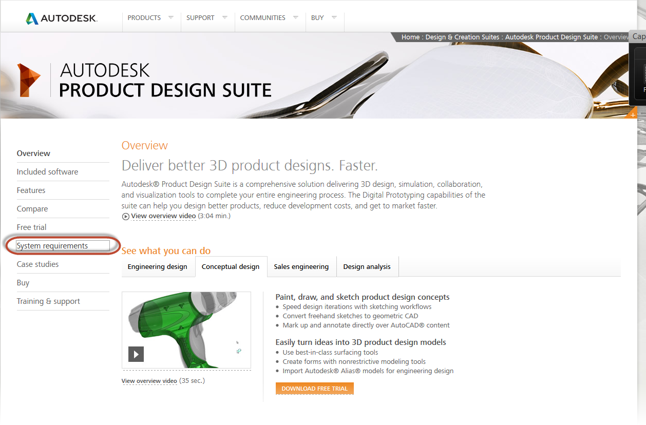
And while I haven't seen any dates indicating when that's going to be, I've noticed that the system requirements are up on Autodesk's website.
I've noticed that it looks like Windows 8 is getting support, which is good news for many, I'm sure!
The Product Design Suite Page
So if you're thinking of going to the 2014 based products, and you're interested in seeing if your hardware is up to snuff, check out the link HERE and see if how your hardware stacks up!
Earlier today, Autodesk announced the 2014 Suites to the world. Just in this fairly brief preview, there looks to be a lot of cool things coming down the ways. It's something I'm looking forward to diving further into as the details come out!
New tools like Recap for laser scanning have my curiosity captured, along with the improved Inventor to Revit interoperability.
But there is something for all the designers out there. If you're using Building Design Suites, Factory Design Suites, or Entertainment Design Suites, there's a little something for everyone.
Construction geometry in an Autodesk Inventor sketch is one of those topics that doesn't often get talked about. It's not shiny or flashy, it just sits there and quietly does it's job.
Usually, construction geometry's job is to help position a sketch, or to help apply constraints, such as a symmetry constraint to the sketch.
The question I pose in this post is, should I change a line's properties such that the line's acts as a construction line in the "Inventor sense"?
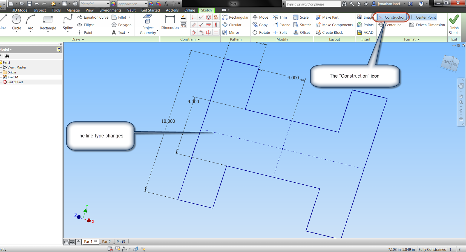
An example of the construction line type in a sketch
I consider using construction geometry a good practice, although "no Inventor police will take you away if you don't do it". In many cases, little difference might be seen between setting construction geometry, and not setting construction geometry.
So what is the difference, and why bother setting construction geometry?
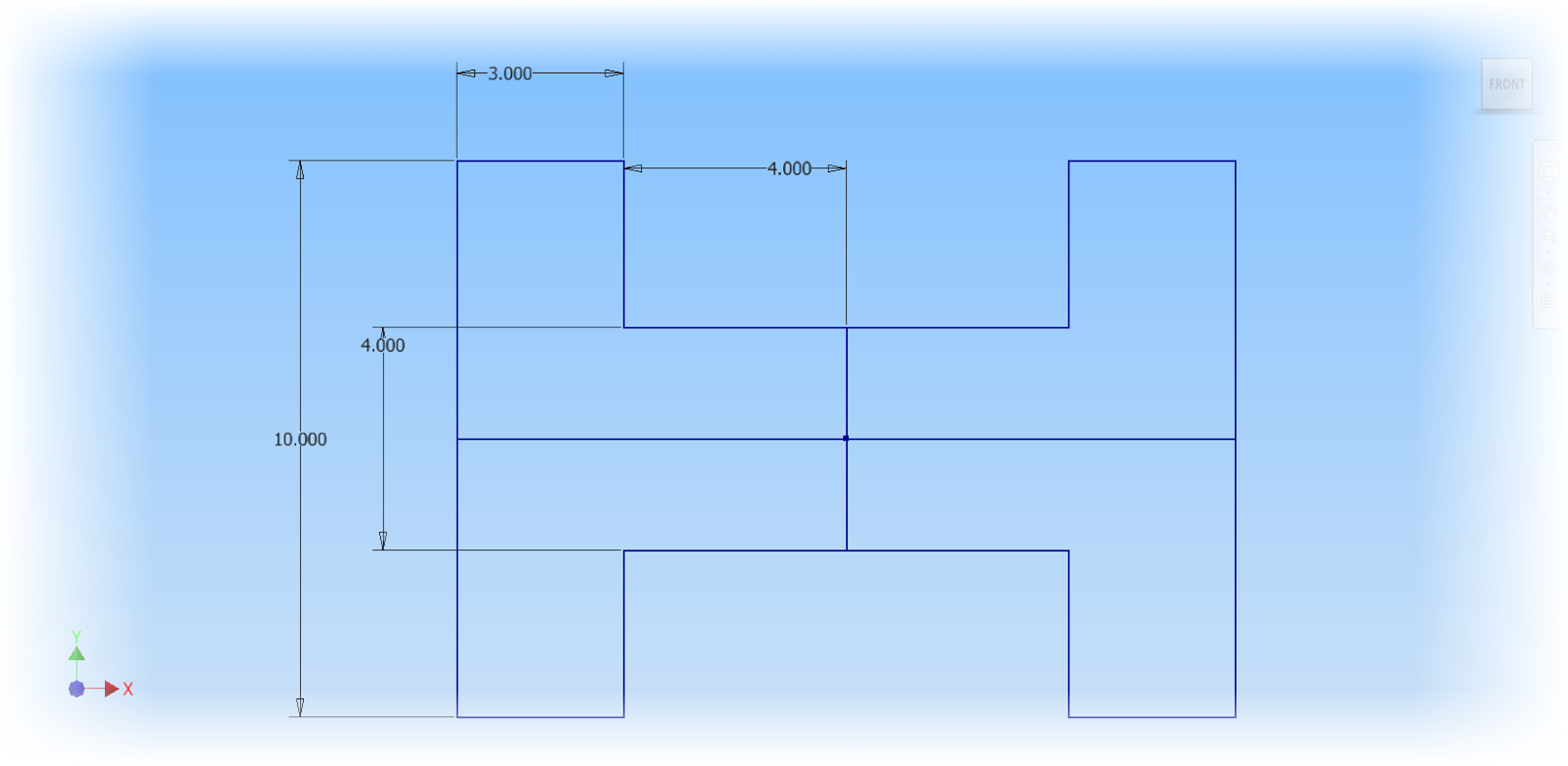
Here's a sketch where I've used horizontal and vertical lines to help set position, and symmetry for a sketch. The lines are all standard sketch lines. No lines have been set to construction.
Notice that all lines are "standard" sketch lines
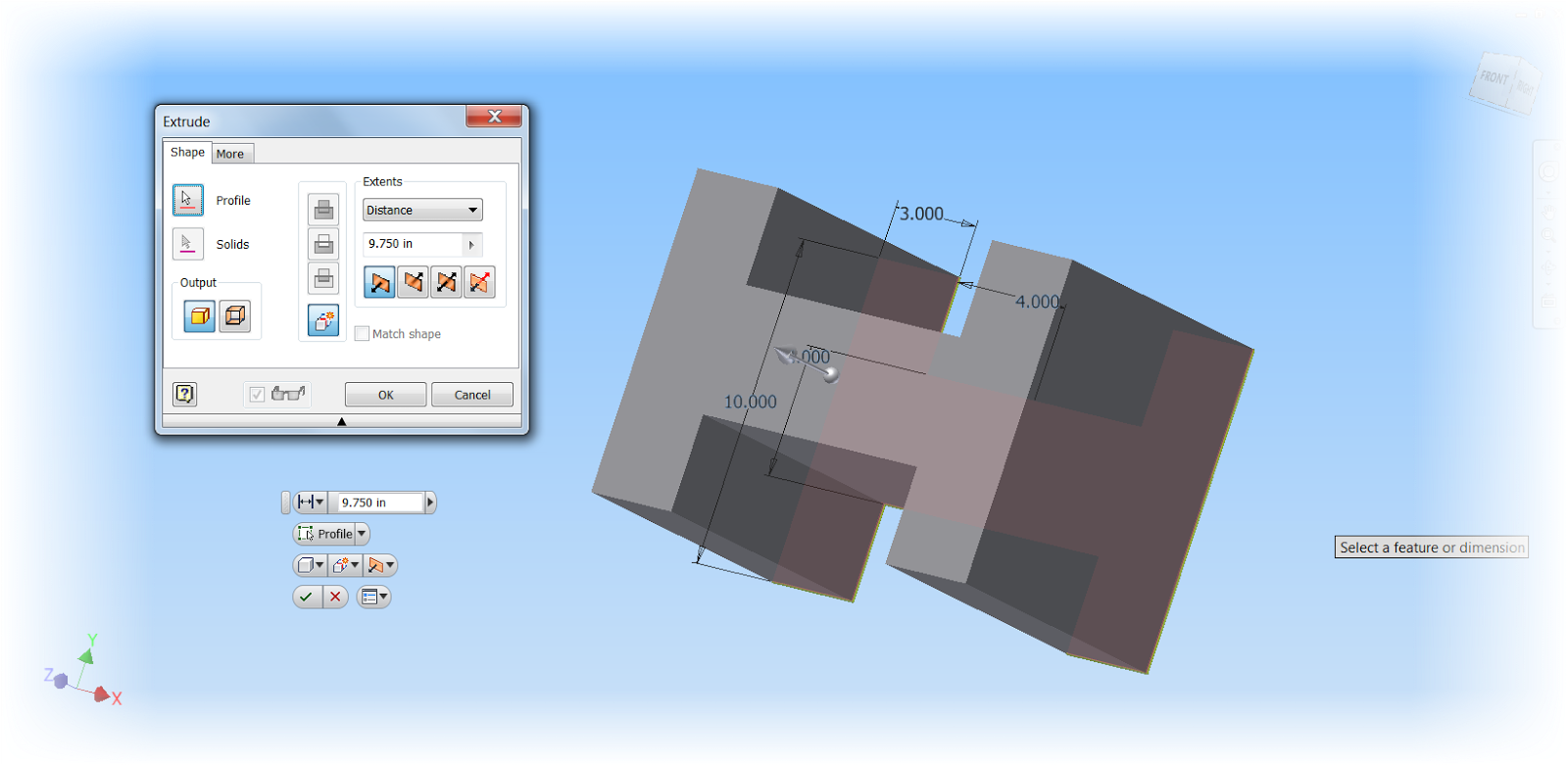
The first thing that usually gets noticed is when the sketch is extruded into a solid. The sketch is now cut up into regions, because Inventor sees each line as a potential boundary for the extrusion. In this case, I have to pick four different regions to extrude this entire sketch.
The sketch broken into regions by its own geometry
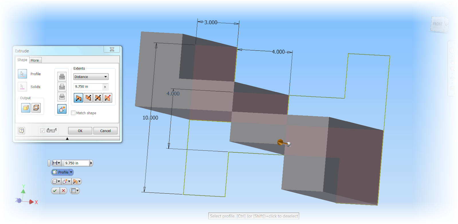
Now picking four regions might not be a big deal. It's just a few extra clicks, right? But now what if you need to put a draft, or taper angle, on the same solid.
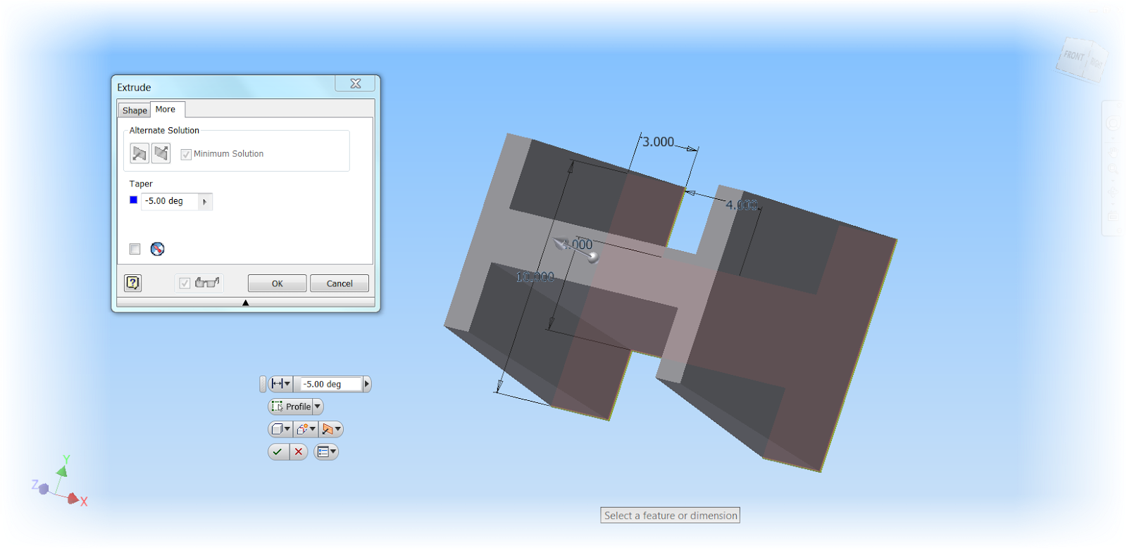
The image below shows the result, since the sketch sees the internal lines as edges for the extrusion, it applies the taper there as well, created the "waffled" solid that might not be the desired result at all.
Internal geometry can change the result of the extrusion
So what happens if I change the properties of the internal geometry to "Construction"?
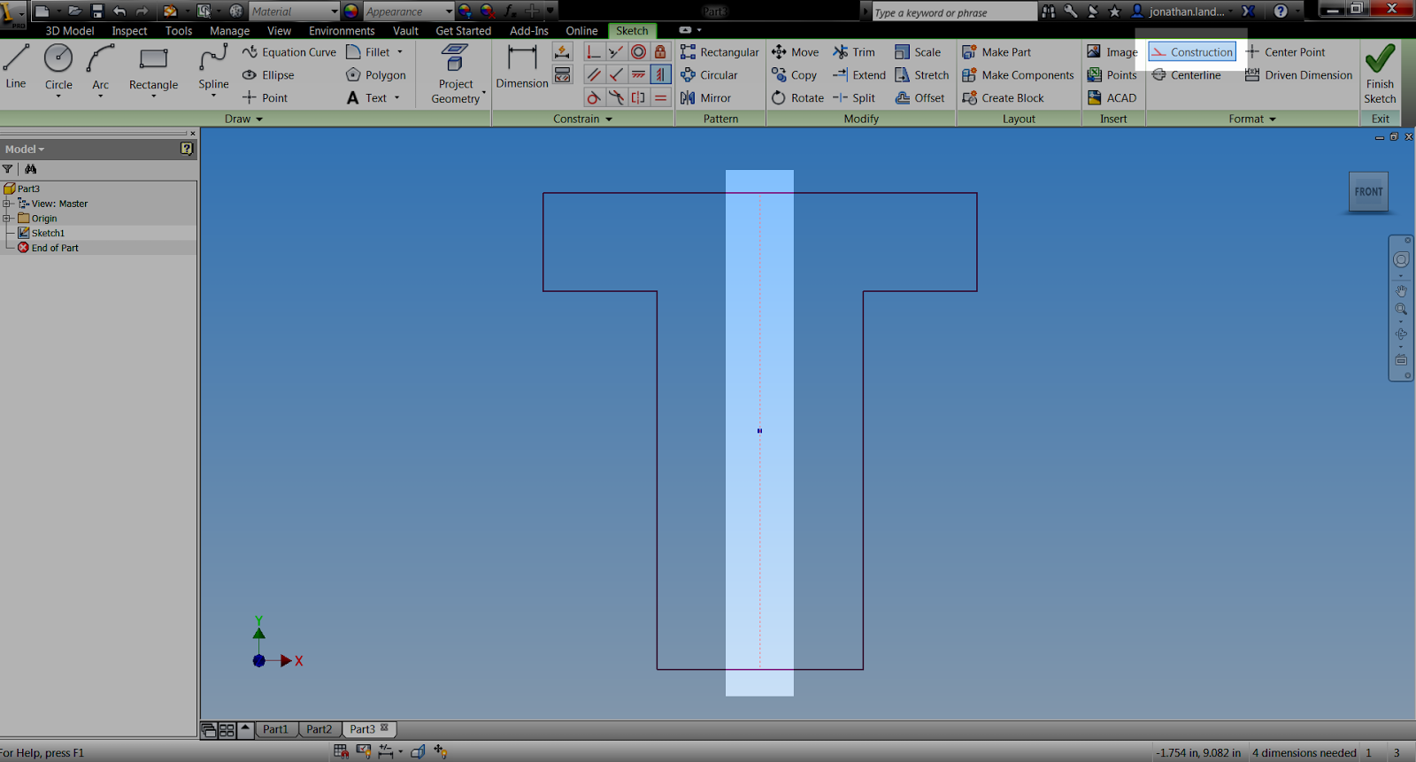
I'll do that by selecting the geometry I want to change, and clicking the "Construction" icon. The line types will change to reflect the property change.
The internal lines after being changed to Construction.
But now, when I extrude that sketch, the behavior of the extrusion changes. First, I don' t have to pick the sketch in quadrants anymore. That's because the internal lines, set to be construction, are ignored as sketch boundaries.
Now the extrusion can be created in one step.
Secondly, if I need to apply a taper, my result is completely different. That's also because Inventor doesn't use Construction geometry as boundaries for a feature. The waffled feature disappears.
With Construction geometry, no waffle!
So there's a little bit on construction geometry, and why it's worth considering. There might be plenty of places it doesn't matter, but in cases like the above, it can be useful. I encourage you to take a look.
And of course, here's a video (with my somewhat raspy voice this week) below!
Recently, I was working on a part where I was controlling the number of features in a pattern using iLogic. Inevitably, I had to figure out how to take an existing feature, and change some of it's values with iLogic.
But I didn't remember a lot of the details, like parameter names, or even the exact context for the command.
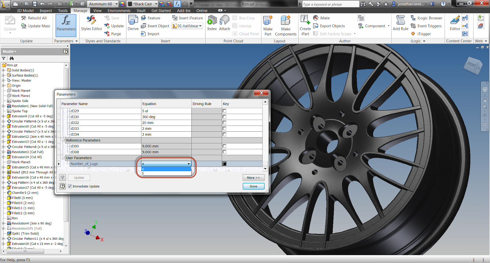
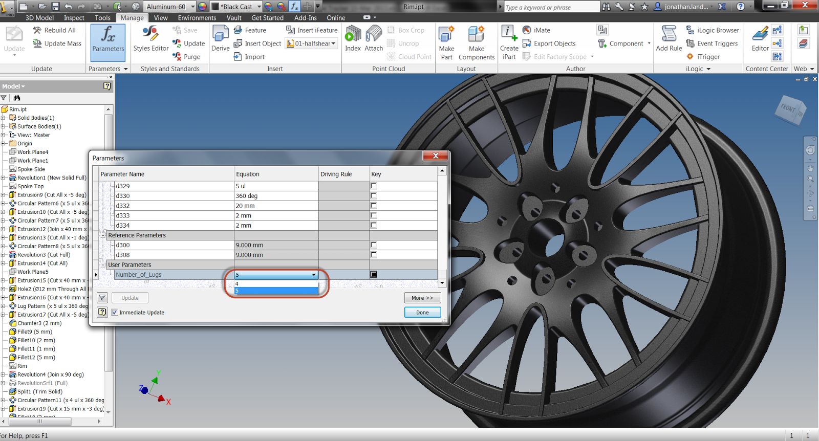
Take a look at this automotive rim (it's just a sample file I'm using). I want to control how many lug holes the rim has.
This is the rim I'll be working with
Even though I've given custom names to the pattern that controls the number of holes, as well as the parameters driving the pattern, I may not know the names off hand.
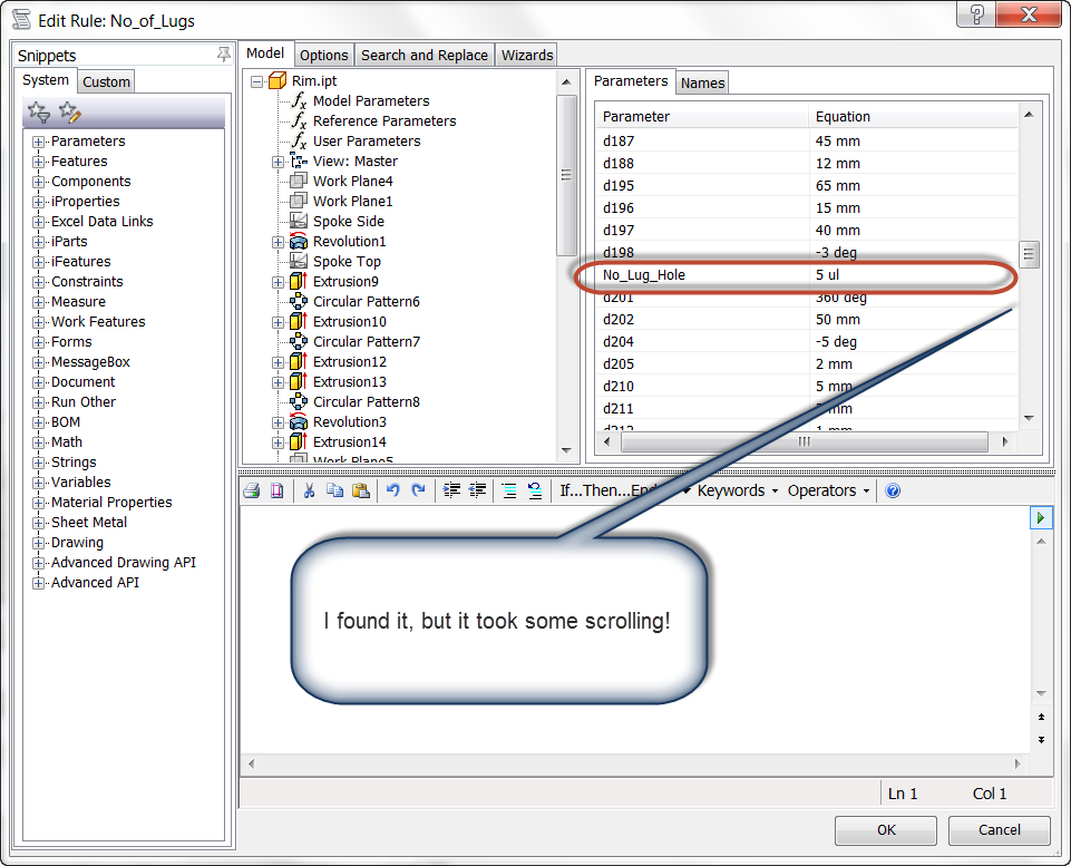
I could pull them from the browser in iLogic, but that could be very time consuming if there's a lot of parameters to sift through, and it can mean a lot of scrolling up and down until the parameter is found.
And this is only one parameter, what if there were more?
The parameter found, after a lot of scrolling up and down, though.
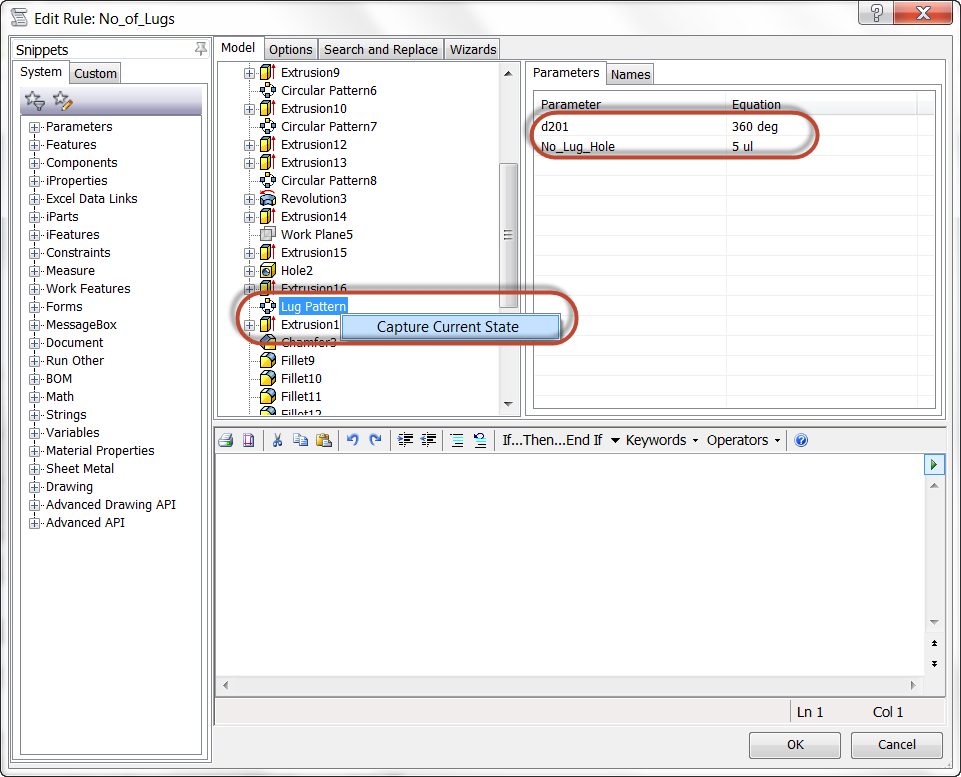
Another way I found that can be extremely helpful is to locate the feature, which even though there's a lot of them here, is easier to locate than a single parameter. Once the feature is selected, right click on it and choose "Capture Current State".
Notice that I renamed the feature too. It makes the feature I'm looking for a little easier to find.
Capturing the current state of the feature
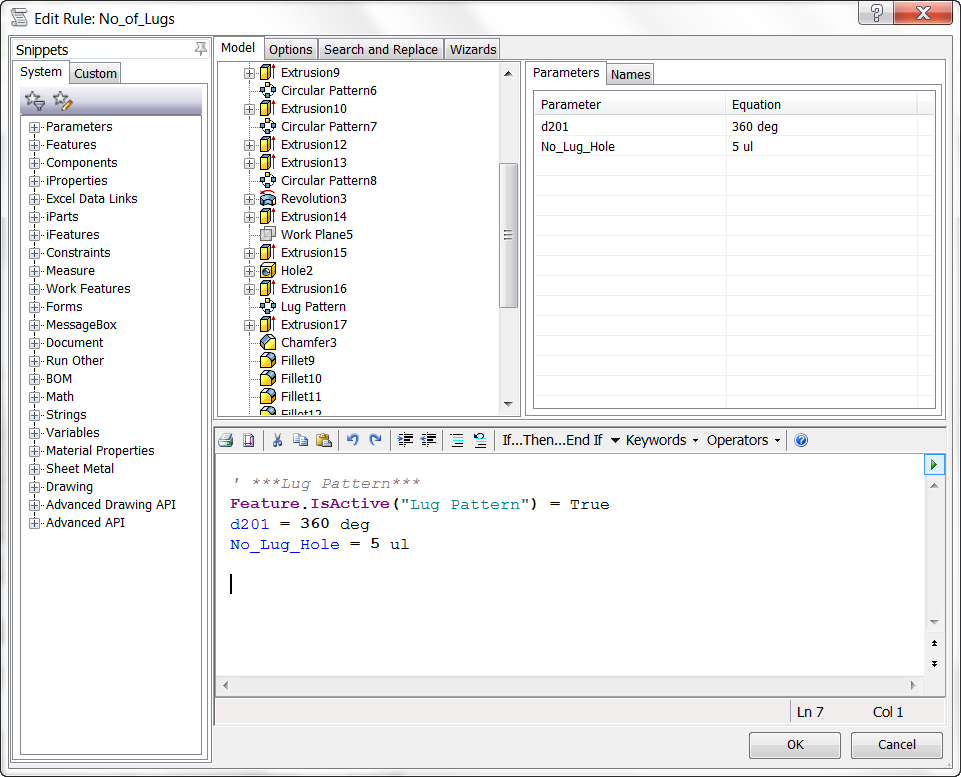
Once the state is captured, iLogic gives me information about the current suppression of the feature, as well as grabbing the parameters associated to the features.
The current state captured
The bonus of this method, is that I can use these values as the basis for creating my rules. I'll start by adding my If/Then/Elseif statements.
Now, I could turn off my pattern completely if I changed the "True" to "False", like the example below: Feature.IsActive("Lug Pattern") = False
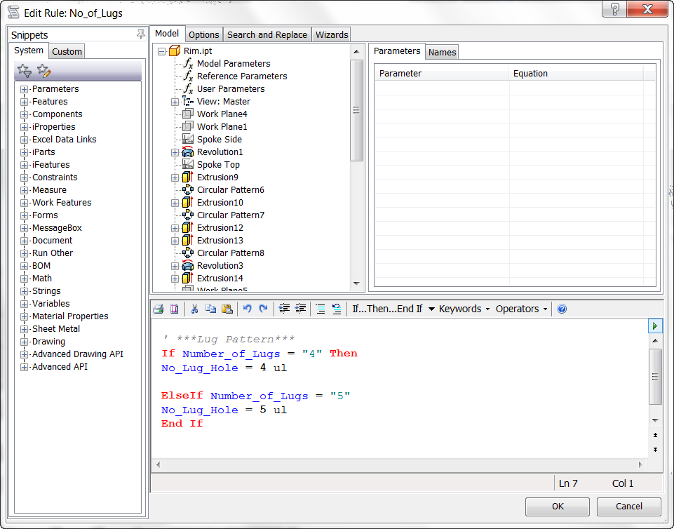
But in this case, I'm only changing the number of Lug Holes, so I'm going to remove the lines that don't pertain to the number of lugs.
The final rule is shown in the image below:
The finished rule.
Now the rule can be checked, and verified.
4 lugs, check!
5 lugs, check!
Now this rule can be expanded by getting other states, or by using any combination of iLogic techniques.
For more information on creating an iLogic rule. Check out my post from the archiveshere.
Today, I'll be skipping the usual Monday quote due to a birthday holiday. I turned 40, and crossed into my next decade of life, which I do hope to make the best ever!
Once again, I found myself snowboarding in Mammoth, joined by good friends and having a good time.
It was incredible spring conditions! And I rode until my legs quit working!
So here's a few pictures, and I'll have a new post coming "techie" post coming up soon!
Riding up the gondola to the top
A gorgeous spring day
A view from the top of one of the chairs. The views alone are worth it.
The view into the Sierra Nevada range from the summit. Yosemite and Half Dome can be seen from here!
Last week, my post showed how the orientation of a model could be changed as it was being imported into Autodesk Showcase. (You can check out that post here)
But what if the file has already been imported? Marion Landry of Autodesk shared a tip via the video comments that pointed it's possible after import too! It's definitely a valuable little jem of a tool I didn't know was there!
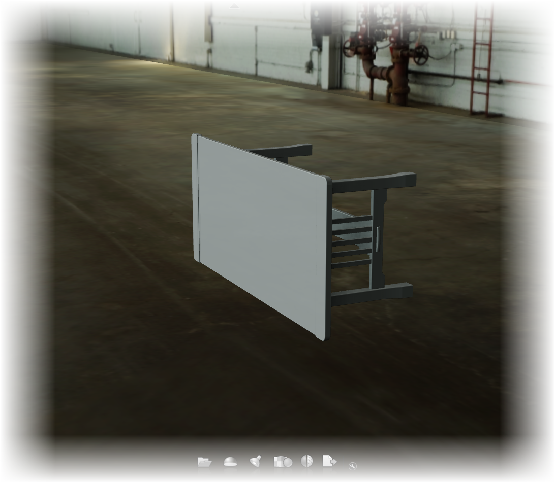
I'm starting out with my model already imported sideways. So there's no chance for me to fix it using the methods I used in my previous post.
It's in sideways, and now how to fix it?
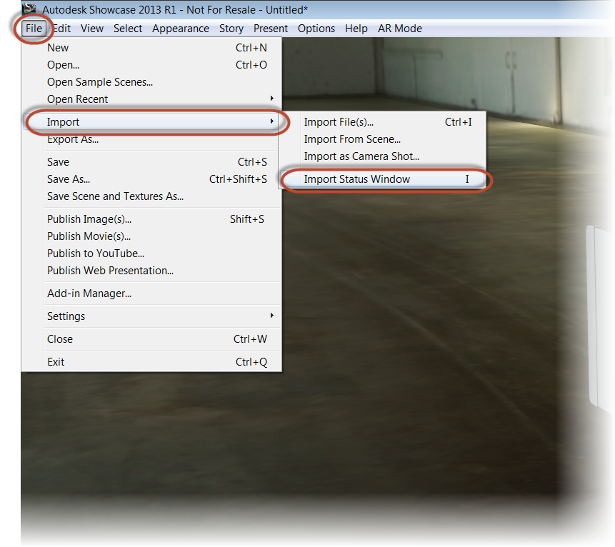
But to fix it afterward, all I have to do is go to the File>Import>Import Status Window menu, or just hit the "I" key.
Locating the import status window
Once the Import Status window appears, I'm going to right click on the name of the imported model under "Source Files". Choose "3D Model Properites.
It's important to right click on the imported , or 3D Model Properties won't appear!
Now, I get the "Original 3D Model Properties" dialog, where I can change the units, and the "Original Up Axis". Choosing "+Z", the model is reoriented!
So there it is, a quick way of changing orientation after a model is imported. Thanks to Marion for taking a few minutes to show this valuable tip!
Sometimes a that clanking sound I hear is a wrench hitting hitting my proverbial works.
And when importing files into Autodesk Showcase from another system, the import orientation (or disorientation), can be that wrench.
Take this for example. Sometimes a file imports, and instead of being right side up, it's completely on its side.
Blast it!
The easy way to fix it is to use the Transform Handles in Autodesk Showcase to correct the problem. But what if there are positional alternatives that need to be preserved? Rotating with Transform handles can sometimes mean rebuilding the alternatives.
Rotating with Transform Handles is sometimes an option
Fortunately, there is another option when importing files.
First, when in Showcase, choose File>Import>Import Files
Preparing to import a file.
When the import dialog box opens, choose the "Settings" button.
Choosing the import settings
Once the import settings dialog box appears, the setting for "Original up axis" can be seen. This is where I can tell Showcase "which way is up".
Note that you can also see the "Import Representations" checkbox in this dialog box. So Inventor representations can be imported in as well.
Changing the orientation
If I take a quick look at the file in Inventor, I can see the +Z-axis corresponds to the top of the table.
Seeing this, I'll choose the +Z radio button, and import the files.
Selecting the +Z option
The file will import, and the orientation will correspond to the "up axis" I selected.
Oriented with representations created as alternatives!
And if you're looking for the usual video that accompanies my blog posts, here you go!
I decided to close this weeks blog with something from the 3D printing world that I found pretty interesting, and not just because of the "high fashion" aspect.
The first time I saw a 3D printing machine was back in about 2000 or so. The material was expensive, fragile, and by today's standards, difficult to work with.
And although I haven't worked closely with a 3D printing machine in years, I'm still fascinated by the technology, and watch with bated breath as 3D printers become more mainstream, and accessible to the average person.
Earlier this week, I ran across an article talking about how the model Dita Von Teese wore a gown that was actually printed on a 3D printing machine.
Go ahead and make your jokes about the article being intereting because of the super model angle........... Okay!
The subject matter aside, the idea that a wearable garment can be printed and worn by someone. Just think of the possibilities.
Need a splint, cast, or sling? Print it!
Does someone need a special harness, mount, or accessory? Print it!
True, the technology may have to mature some more, but it's come a long way already. It's amazing what can be done today, I'm looking forward to what they might be able to do in the near future.
When designing, there are times that alternate positions for components must be shown to ensure the design will perform as intended.
This might be an arm extended and retracted, or a door or drawer opened, and closed.
There are also times those alternate positions need to be shown in a rendered view to properly convey the design intent outside of the design product.
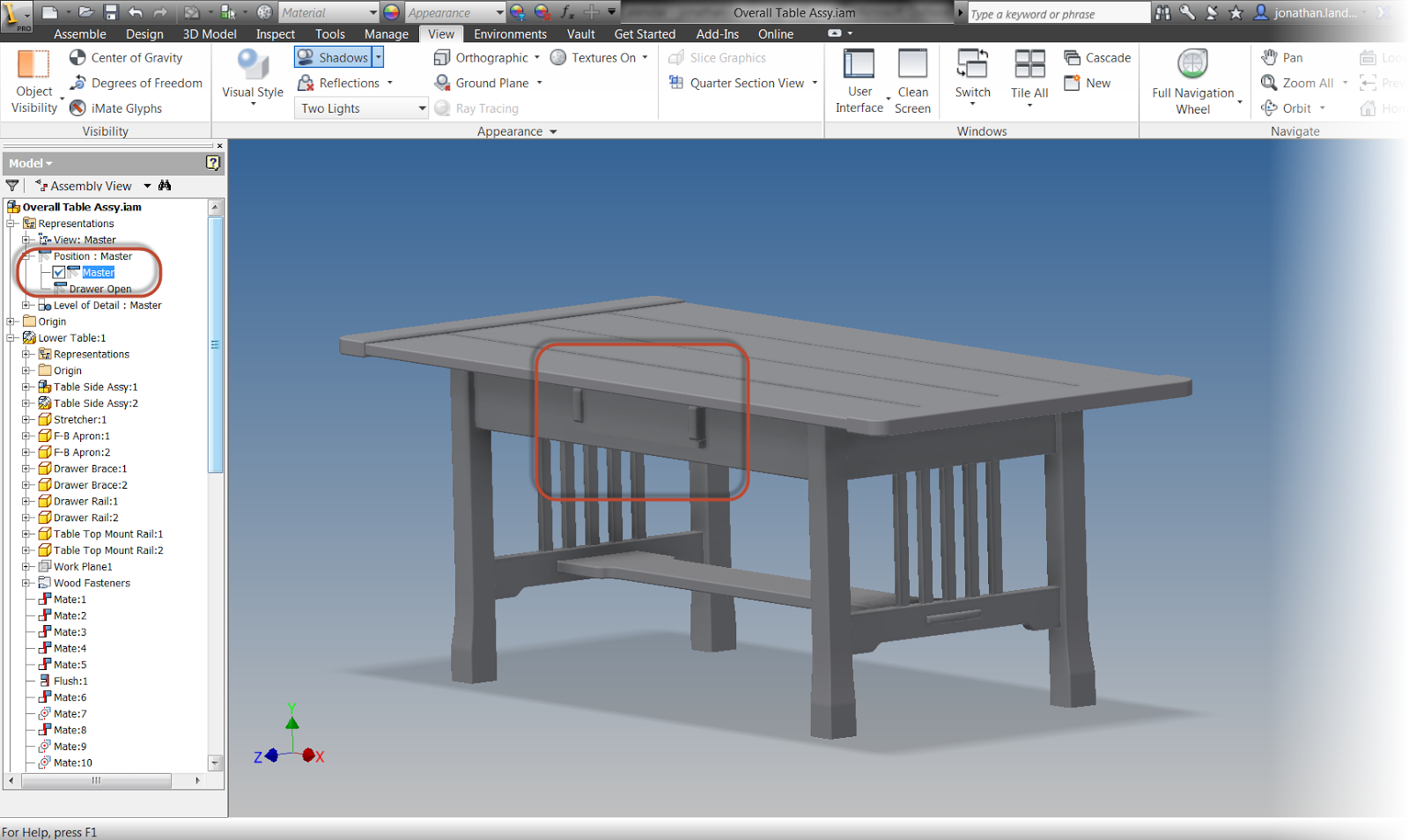
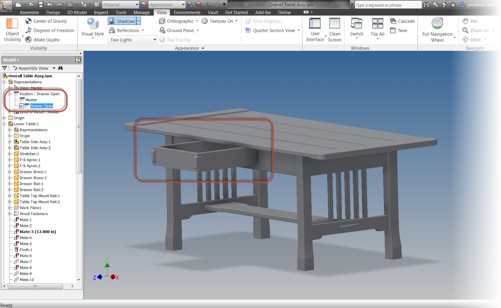
When using Autodesk Inventor, Positional Representations are used to accomplish this task in design. For example, here I'm showing a coffee table with drawer open, and drawer closed positional representation. (For instructions on how to create a positional representation, check out my previous post here)
A positional representation showing a drawer closed
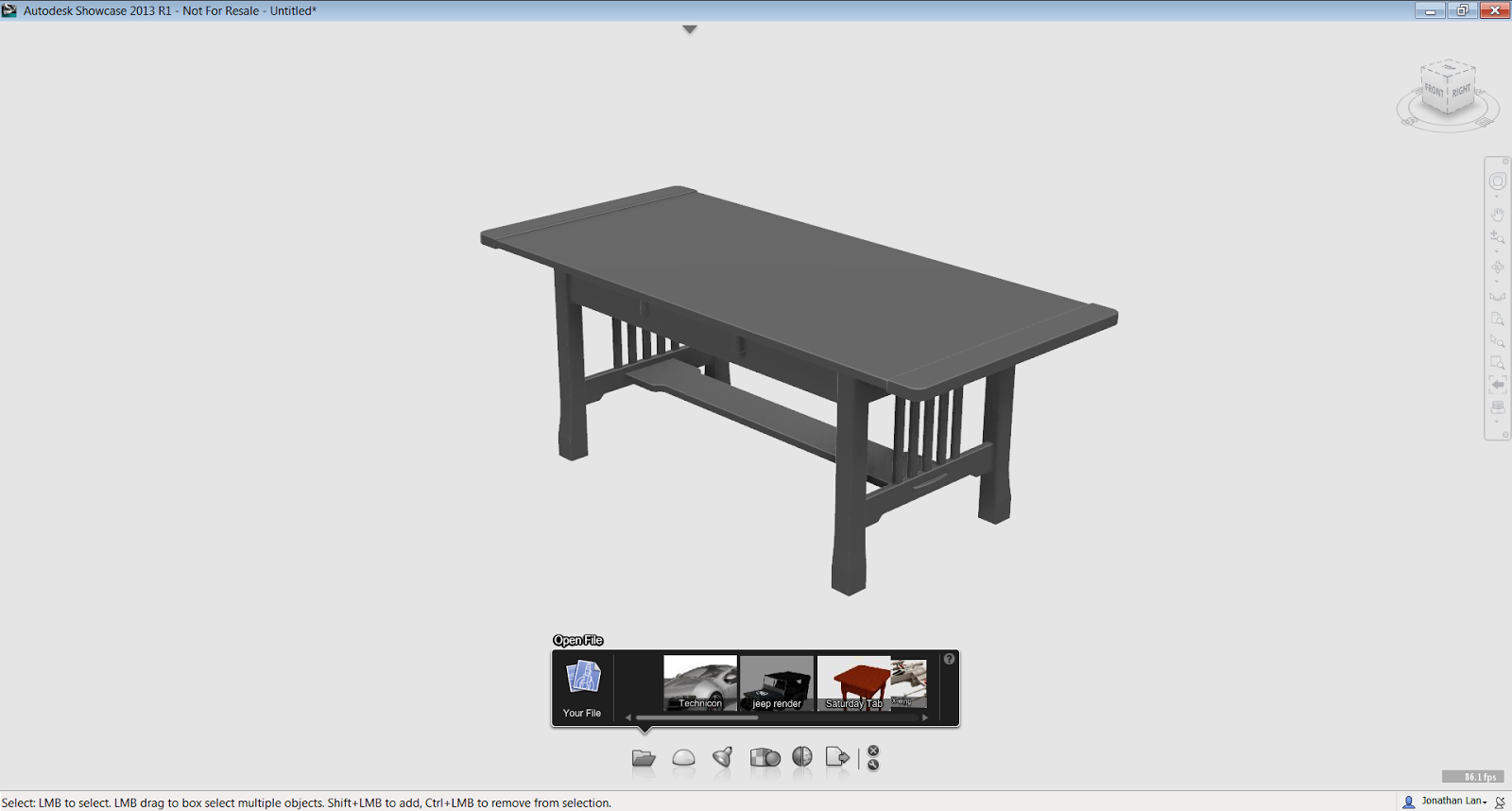
Autodesk Showcase uses Alternatives to create alternate positions for the renderings. Here is the same table shown with alternatives in Showcase
The model is imported and ready with the drawer closed
The alternative with the drawer open is already created.
While each product can work independently and create their own distinct representations of the components, there's no reason to recreate work twice. What if what I want to do is reuse the representations in Inventor, and use them to create alternatives for Showcase?
Fortunately, Inventor and Showcase has a "Suite Workflow" that allows the representations created in Inventor, to create alternatives in Showcase.
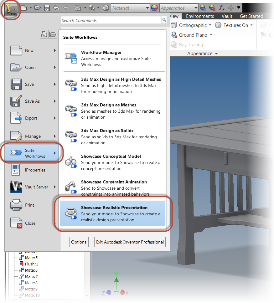
I'm going to begin with my coffee table open in inventor, then I'll click on the Application Icon (The big "I"), I choose the "Suite Workflows", then choose, "Showcase Realistic Presentation".
Starting the representation
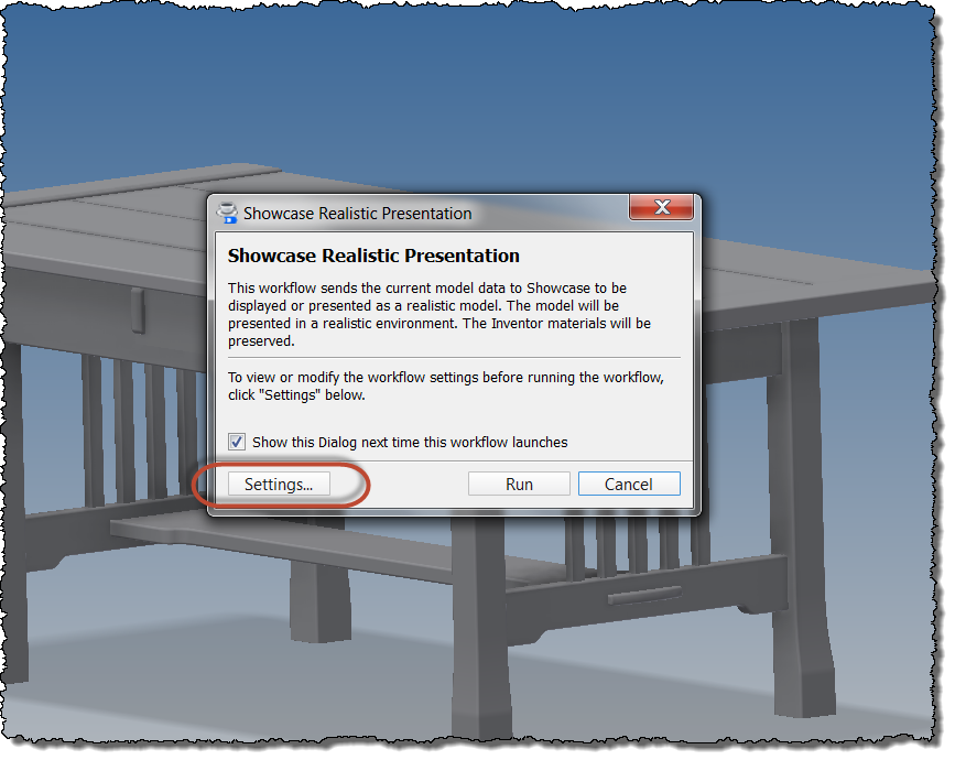
A dialog box appears that describes what this setting will do. I'm going to choose the "Settings" button to make changes to how the model appears on import.
Selecting the settings for import
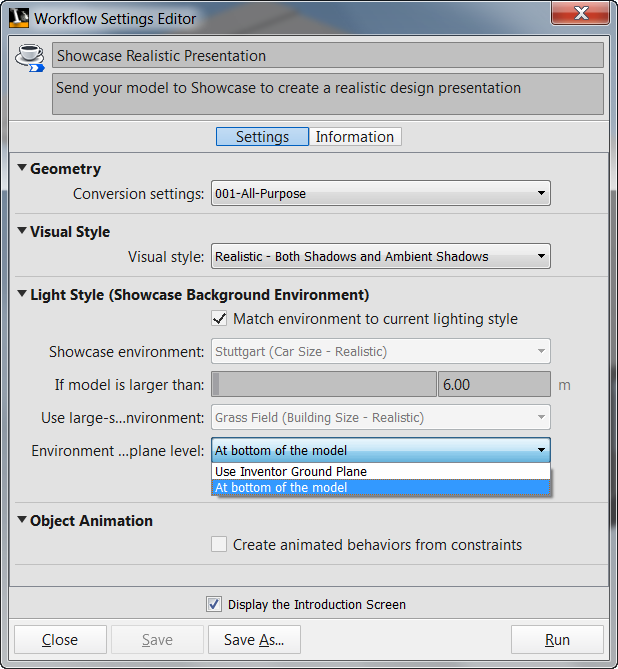
Here the settings for import can be set, such as the conversion settings (the density of the facets making up the Showcase models), Visual Style, and Lighting Style can be set. Most of these can also be set in the Showcase scene, so I take defaults for most with one exception.
I do like to set the "Environment... Plane Level" setting to "At bottom of the model". While your settings may vary, this setting is works best for the models that I create.
Workflow Settings
Now I go ahead and click "Run".
Pulling the trigger and running!
The model will process, and will open in Showcase. Both alternatives are created by the positional representations
Now all I have to do is apply the desired materials and lights in Showcase, and finish creating my model in Showcase. No recreation of the drawer open, or drawer closed. Just use what Inventor provided to Showcase!
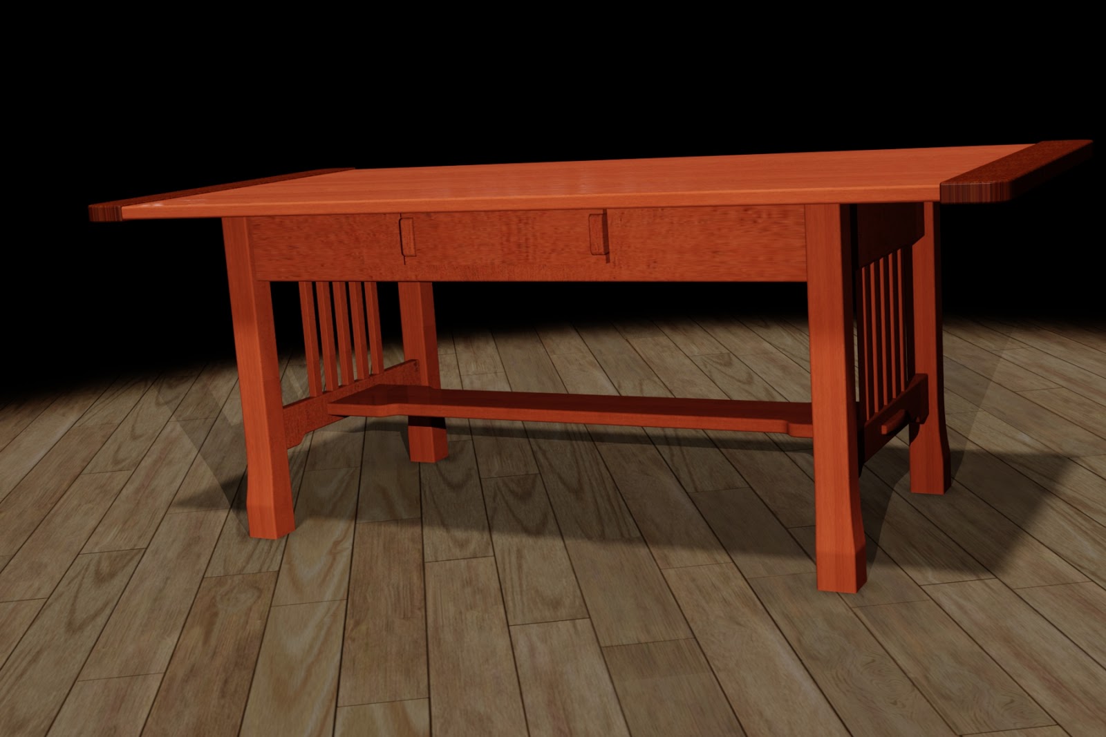
A quick rendering in Showcase with the drawer close
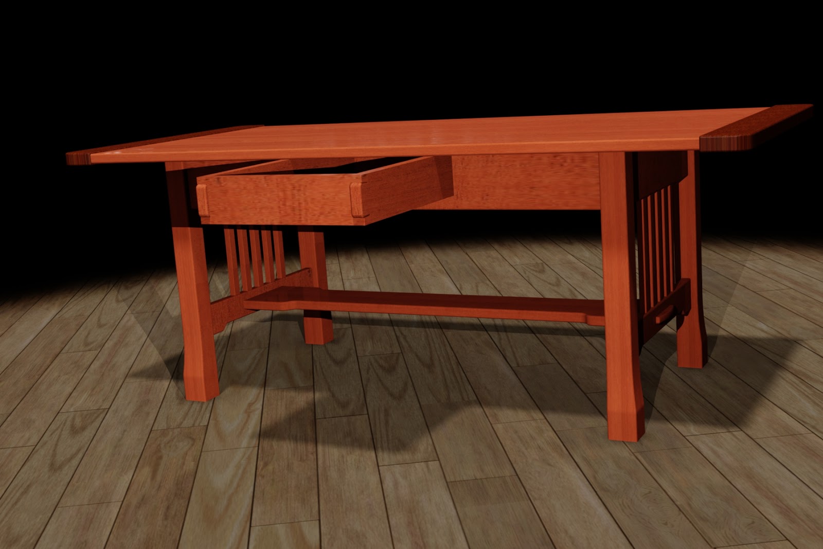
The same scene with the drawer open via the alternative.
And to see the steps in a video format, just take a look below!


