Find us on Google+ Inventor Tales: Inventor Drawings
Showing posts with label Inventor Drawings. Show all posts

Saturday, March 12, 2022

The Chamfer Note. Does It Say What You Mean?

Many CAD tools contain a chamfer note that I would describe as a leader style. 

You've probably seen it, probably used it even. 

It utilizes a leader to point at the chamfer, and contains both the chamfer distance, and angle in one simple note.

The advantage of this style is it's compact, easy to read, and especially easy to place when the chamfer is packed into a crowd with other nearby dimensions. 

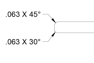
But this dimensioning style as a subtle disadvantage. This style of dimension doesn't identify the direction of the chamfer. So if the chamfer angle is something other than 45 degrees, the angle direction is open to interpretation. 

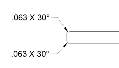
Even though the chamfers are different, the callout is is the same. 
It's also correct in both cases.

That literally means that a chamfer in either dimension meets the print. That can cause confusion, and possibly "heated debates" when a parts acceptance or rejection hangs in the balance. 

The other option is to call out the chamfer distance and angle as separate, distinct dimensions.  This identifies the direction of the chamfer much more clearly.  


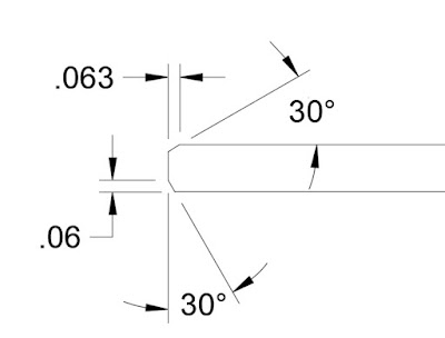
Of course everything is a trade off, and this method does take a little more room on the page than the leader style. Even on the image above, you can see that the page is a bit more cluttered, and someitmes a detail view is required to ensure all dimensions can be clearly seen. 

In the end, I find I use both. The leader style is used for 45 degree chamfers, since there isn't really an angle direction to speak of. However, when the chamfer is an angle other than 45 degrees, it's time to employ the explicit style, and make sure the direction is clearly shown. 

Ultimately, it's up to you which chamfer style you use. Perhaps you have the advantage of tribal knowledge to correctly identify these features. Or you have other means to make sure the chamfer is cut the correct way. 

If anything, this is a good practice hailing from the time when "back to the drawing board" was a much more literal statement! 

About the Author:

Jonathan Landeros is a degreed Mechanical Engineer and certified Aircraft Maintenance Techncian. He designs in Autodesk Inventor at work, and Autodesk Fusion 360 for home projects. 

For fun he cycles, snowboards, and turns wrenches on aircraft. 


Sunday, December 13, 2015

Text Masking - Making Leaders Disappear Since 2000.

This week's post is short and sweet, due to a little craziness during the week, but I still hope you all find it enjoyable and helpful!

The simplest things can drive you crazy,  One I encountered in Autodesk Inventor was a leader that seemed to randomly disappear.  It would just stop in one place, and start in another.

There seemed to be absolutely no good reason for it.

Why is this leader cut off?
It can be really puzzling.  The first time I encountered it, it completely threw me off.  It took a little bit of clicking and dragging before it finally dawned on me.

If you study the image above, you can actually see it, if you know what to look for.

The text box covered up the leader for the balloon.  Because of that, the masking "erases" the leader.  Dragging the leader out of the box, or dragging the box away from the leader, cause the leader to reappear.

And the truth of the fact was I had been a little careless and "whipped" the text box and made it far larger than it needed to be.

Here, I've shrunk the box to give the leader room.

It's so simple, yet at the same time, it can be so frustrating.  But in the end, it's really simple to fix.

So what's my suggestion?

Keep your eyes open, of course!  But also be aware that dragging a huge text box, because "it doesn't make that big a difference" can be asking for trouble.

Why?  It can cause a huge difference!  But just be aware, and know what to look for, and a big frustration can be reduced to just an "oops".

Sunday, November 22, 2015

An iProperty in Time - Linking Autodesk Inventor Properties to Your Drawing

Creating and modifying prints often comes down to details.

Many errors I've seen (cough, made myself), are smaller, easier to miss details.  One example, is forgetting to update a text field.

This is not the print you want to miss a detail on.
Just ask this engineer.  He's got a tough boss!


These are often notes that are hiding in a corner in the drawing.  A part number in a note is a prime example. 

But what if I told you there was a way to set up your template with a field that automatically read in the part number?  So that every time you placed a part in the drawing, the drawing automatically read in that part number. 

There is, and this is how. 

Start out by typing text, just like you have countless times in an Inventor drawing.  But choose the settings indicated in the image below: 


Here are the steps the image describes.

1) Start the text tool.  You won't get far without this step.

2) Start typing! You'll need to get to the point where you're ready to insert the text.  

3) Set the Type to Properties - Model.  This makes sure that your reading the property from the model placed on the drawing. 

4) Property - This is the property being placed in the text field.  In my case, I'm using part number, but there plenty of others to choose from.

5) Insert - This is "pulling the trigger".  This places the text in to the text field. 

Next, you'll see carets with the property insert into your text editor.  Part number appears in my case. 
After this is done, complete typing the note you need.  Once you hit OK.  The text will appear on the drawing and the property's value will be read in. In my case, it's the part number 2015-48-12.


Should the property change, the field will update, wherever it's called out on the drawing, including multiple locations, if you have them. 

In my example, I'll change the part number from 2015-48-12 to 15-1595-ABLE.   Which, let's face it, part numbers, among other fields, can change.


Once the field is updated, the drawing will read that property from the model and automatically update. 


There are the steps to get a property linked into a text field.  To get real bang for your buck, add required fields to your template, and get rid of some of those repetitive, and easy to forget tasks!

And look at what other fields you can add.  There are plenty to choose from!

I did create a video for this one using Autodesk Screencast.  No sound, I'm afraid.  But life has been keeping me *just* busy enough to keep me out of my little editing room!


Sunday, October 18, 2015

Getting Your Autodesk Inventor Threads to Stay on by Default

Foreword 

A couple of notes before you read the whole blog!

  • My tests were conducted with Autodesk Inventor 2015, the version I'm currently using at work. Other versions may behave differently!
  • If you're comfortable editing your registry, follow the instructions at Being Inventive here, and you won't need to follow the steps I describe.  

If you choose to read on... Welcome!

Thread solo! 
Relearning design engineering has been an eye opening experience, and there's no doubt it will continue to be.

I had forgotten, in the mad world of hustling drawings, every little thing you can do to make your life a little easier helps.  Something a little faster or a little more accurate can save you a lot of time.

One setting that got me on a drawing was the default thread behavior in Inventor.  It's unchecked by default, which means that threads won't display in a drawing.

It's not a big deal to check the box and turn it on.  The trick is remember into to check the box!

What would really be desirable, is to set it once, and have it stick that way.

Fortunately, there is a way!  Here are the steps.

The first thing to do is start a base view just like you would any view.


But before you place anything, make sure to check the "Thread Feature" option to turn on the hidden lines that represent threads.

This part is important.  Make sure to check the box before placing the view!

Check this box BEFORE placing the view.

Once the box is checked, place the view.  The threads will not only show, but the threads will "persist" and display by default the next time you place a view..

There are my threads!

There is a small downside though.  You'll have to do it for each file type.  That means doing this procedure for parts, sheet metal, assemblies, etc.

It's not difficult, it just takes a little bit of time.

Also, if you want Autodesk to change it, don't shake your fist in the air.  Let them know at the Autodesk Idea Station here!

I've placed my vote!

Photo Credits:

photo credit: The Backup Band via photopin (license)

Wednesday, April 08, 2015

What's new in Autodesk Inventor 2016 - Text in Drawings

In this post, I decided to continue with my discussion on what's new in Autodesk Inventor drawings.

This time, I thought I'd share some of the text improvements that have come a long inside of Inventor.  


First, the dialog box has been changed slightly.  Primarily the layout has been changed, mostly to help organize and streamline things a bit.  


2015 on the left, 2016 on the right

But if you look closer at the screen, you'll also see a few new buttons.  Notice that there's now buttons for bullets and numbering, as well as a button for strike-through.  Now you can create this formatting right in the text box.

The location of the new Bullet, Numbering, & Strikethrough icons.


Also, if you copy from Microsoft Word into Inventor's text box, any bullets and numbering used is kept, so you can change it after it's been placed. 


Just copy and paste and the formatting is preserved.
You might also notice that the Zoom in and out arrows are gone.  But the functionality remains!  Now hold down the CNTL key and scroll the mouse wheel to zoom text in and out.

Once again we have 2015 on the right and 2016 on the left. 

Another nice little add is the ability to change case.  Do you want to force text to have ALL CAPS, all lower case, or Set To Title Case?  That's been added now too!

An example using the ALL CAPS setting


The symbol list has been changed too this should make it easier to locate the symbol you want. 

The reorganized symbol library

And did you notice something in the above screenshots?  There's a preview on the drawing sheet as you type the text.  That's not a trick of screen capture editing, that's the real deal. 

The preview on your drawing, you can see your results as you type!

Finally, should you need to rotate your text, you have the option to do so on screen.  Just grab the blue grip with your mouse, and rotate to the angle you want.

Rotating by dragging on the drawing canvas

And if you still prefer to rotate precisely, you can still do that in the dialog box. 

Changing the text rotation via the dialog box. 
And that's it for now!  A few of the improvements in text editing in Autodesk Inventor 2016.

I can't create a video for this one I'm afraid.  I'm on the road so I don't have any of my video gear with me!

I hope to add one later! 

Saturday, March 07, 2015

Using Copy Properties to Quickly Update Dimensions in Autodesk Inventor

The last few weeks have been comprised of Inventor drawings, comprised of even more drawings for me.

Part of that process included a lot of changing of decimal precision.

A common practice to change precision is to select the desired dimension and choose the dimension style from the format portion of the annotation tab.

Changing dimension style from the annotation tab.
This process works great, but if there's a lot of dimensions, it can get old fast.

Fortunately, there is an alternative to "sucking it up and dealing with it".

The tool is Copy Properties, and it does what it claims, it copies the properties of one dimension, and pastes them to as many other dimensions as you need.

To use this tool, start by right clicking on the dimension that has the formatting you want, and choose the Copy Properties tool.  

Using the properties of a source dimension.
If you  select the dimensions you want to copy the properties to, all the properties are copied.  That includes the tolerances, the style, even the text the text that accompanied the text

.
Pasting properties from one dimension, to another.

So before you select the target dimension, right click and choose Settings while Copy Properties is active.

Locating settings by right clicking while the tool is active.
This gives you an opportunity to choose what properties you want to copy from the source dimension.

The settings screen. 


Once you have the settings where you want them, choose the dimensions you want to transfer the settings to by clicking on them, and those properties are transferred!

You can pick individual dimensions, or even pick using a window!


Once you're done, just right click and choose Done, or hit escape to exit the tool.

Give it a try!

And check out the KETIV YouTube video  below to see it in action!  


Sunday, February 22, 2015

Shimming Your Knowledge - Adding Parameters to Text in Autodesk Inventor

In my last post, I mentioned that I've been doing a lot of work with Autodesk Inventor drawings.

I've found that this week, the trend has continued.  And while this can be a bit monotonous, it has given me an opportunity to blow the dust off some old tricks I've learned over the years.

One common thing I've seen is inserting a certain value into a block of text, such as note text.  These values can be things like sheet metal thickness, bend radius, or any other value that needs to be stated in the body of the text. 

A typical example.  I've added the radius dimension for comparison.

\It's never hard to type these values in, but if the value is just typed, then it's static.  If the value is changed in the model, there's no way to make sure that value updates, short of using the good old Mark 1 memory and Mark 1 eyeball.  


So let's take a look at how to automate that process.  Let's make the bend radius note update automatically. 

Start by editing the text the same way you always have.  Right click on the text and choose Edit Text

The editing screen

Once inside the text editor, focus on the set of bars just at the top of the text editing portion of the screen. 

From left to right, here's the information each pull down contains, starting from left, and working right. 

  • Component - Which component are you drawing the data from.  In this case, the model is named "Sheet Metal"
  • Source - Are you calling the parameter from the Model Parameters, or User Parameters
  • Parameter - The actual parameter you're placing. 
  • Precision - How many decimal places does the parameter contain. 
  • Add Parameter - This will actually put the parameter into the text. 
  • Special Symbols - Expand this menu to see common drafting symbols to place. 

The toolbar to add your parameters in. 

Clicking the Add Parameters button will add the value to the text, but inside of a gray box.  This tells you that the value is being read from an outside source. The sheet metal part in this case. 

Using the Add Parameter tool to make the magic happen!

Click OK to complete the operation. Now when that value changes in the model, the value will automatically be saved in the text!  


But there's one more thing.  What if you want to adjust the format even more?  To do that, right click on the text again, but this time, choose "Edit Unit Attributes". 

Now you can change the format of the units, including units, precision, and format.  In this case, I removed the leading zero, and added the unit string to make sure the units fit my standard.


All that's left to do, is hit OK, serve, and enjoy!  The units and leading zeros are gone, and the value on the drawing will update should the model change! 


And once that's done, you're all set!  Take a look at this tool, and see how it can help you!

If you prefer to see this information in video form, take a look at the video below!


Sunday, February 15, 2015

Shimming Your Knowledge - Associating Text and Symbols to an Autodesk Inventor Drawing View


Lately, I've been doing a lot of work inside of Inventor drawings. During that time, I was asked how to make sure that all my text and symbols will move with a view.

If you've used Inventor for a while, you may have noticed that if you put in a text or symbols next to a view, they will stay behind if you want to move the view.

Everything looks right here.

After moving the view, the symbols stay behind.

It's usually not a big deal to move the text and/or symbols later, but there's always an opportunity to make a mistake.

And it's just a pain to move the symbols back to where they were!

But there is a way you can make the text and symbols move with the view, and that's to start off by placing the text and symbols using the leader options

Use leader text, and the leader options to place the symbols

If you place the text and symbols with leaders, the move with the view that they're attached to.


Place the symbols using the text as leader, and with symbols


But we didn't want leaders, right?

But that's okay.  If you right click on the leaders, you can delete the leaders, leaving the text and symbols behind. Just choose Delete Leader.

Add caption

The best part?  Even with the leaders removed, the association remains!  If the view is moved, the text and symbols now move with the view.

Now if the view is moved....


The text and symbols move with it! 

And that's how you can make sure your text and symbols update the way you want them!

For a video of the steps I've described above, check out the video below!


Wednesday, June 18, 2014

Splitting Tables and Moving to Different Drawing Sheets - New In Autodesk Inventor 2015

“A table, a chair, a bowl of fruit and a violin; what else does a man need to be happy.”
 Albert Einstein

It's been a busy few weeks.  I've traveled to Michigan, taught Inventor classes, and even put my head into a Vault server once or twice.

Finally, I find a little time to talk about a new feature in Autodesk Inventor 2015.

This one is quick, and it's simple.

Moving a split table, such as a parts list, from on drawing sheet to another.

It's subtle, but it's a significant new feature that several users may find helpful.

In my example, I'm going to use the parts list table shown below.  It's crowding my drawing a bit, so I'm going to split it, and move one end of it to another sheet.

An example of my sheet as it looks now!
First, I right click on the cell where I want to split the table, and choose Table>Split Table

Splitting up my table
The table will split, and I can drag the parts list into two different locations.


But what I really want to do, is drag the template to a completely different drawing sheet.  For this, I need to switch to the drawing browser.  When I expand it, I can locate the Parts List, and see where it's split into two separate items.

The two halves of my part list

Now, all that's left to do is drag the parts list from one drawing sheet, to the other.  However, do this in the browser!  This will make sure it works correctly!

Drag and drop the sheet from one sheet to another


Once that's done, one half of the Parts List will reside on one sheet, the other half on the other sheet.  The icon even indicates this, as well as which sheet holds the original!

The sheet shown in it's destination.
The sheets shown together
So there it is!  A nice new feature in Autodesk Inventor 2015!  Take a look, give it a try with all the table types!  It works with everything I've tried, except the revision table!

And feel free to throw a comment below!

And one last note!  For the full list of What's New in Autodesk Inventor 2015, check out think link!