Find us on Google+ Inventor Tales: iLogic and Customization
Showing posts with label iLogic and Customization. Show all posts

Monday, July 30, 2018

Fusion 360 - Keyboard Shortcuts are here at Last!

Last week, Autodesk released a new update for Fusion 360, and while there's a few updates, the one that's getting the most attention is the addition of keyboard shortcuts.

Creating a shortcut

Now, if you'd like to setup your own custom shortcuts, you have the freedom to do it.  Just start a command from the pulldown menu, and click the "3 dots" on the far right of the toolbar.

Click the dots1

Now the Change Keyboard Shortcut dialog appears, and you can type in the shortcut to almost anything.  In this case, I chose to use "Shift+R" for a 3 point rectangle. Then hit OK, and you're ready to go

Changing the shortcut
You may have seen that I typed "almost anything" in the above paragraph.  There are some reserved shortcuts that can't be changed.  Among them are the standard Windows shortcuts, such as CTRL-S for save.  There are also shortcuts reserved by Fusion 360.

Man!  I'd love to make "S" a shortcut for "Create Sketch"!
And if you don't like any of the shortcuts you've created.  You can always restore to default! 

And finally, this wasn't the only enhancement to be introduced in this release, for the rest of them, follow this link here!


Sunday, September 11, 2016

Constraining Content Center Components in Autodesk Inventor - An Alternate Way

Recently, I've been doing a lot of work with content center lately.  I've been building content, publishing content, and fixing content.

It can be tedious, but it can also be a lot of fun.

But there's one trick I've picked up in my travels.  It's how to constrain content, in particular custom content, a little more quickly than by using the standard method.

Now before I get started, one disclaimer.  I'm using standard content to demo my blog, I didn't have customer content center fasteners I could share with you, so I had to borrow the standard.

Since I'm using standard content, I also I know I could use Autodrop, but the point was to show an alternative.  All I ask is you bear with me on the standard content part.

So with that said, it's time to get started.

Of course you'll need to place your content from the browser.

Selecting content to place

2) When the fastener previews, right click and choose the size you want to place.

Choosing the size of your content center fastener

3) Next left click to place your fastener, but here's the trick.  Without you even knowing it, the insert constrain is active.  Before you left click to place the next fastener, left click under the head of the fastener you wan to place.

Selecting under the head of the fastener
4) Now select the mating hole, the insert constraint will be created!

Completing the constraint with a second click on the mating hole
5) All that's left is to repeat the steps if you have multiple fasteners!  You don't have to exit the command!

Repeating the step for multiple fasteners. 
So give it a try if you have content you're using, particularly custom content.  I've found it helps me out, I hope it does the same for you!


Tuesday, August 05, 2014

Read Only Inventor Flies Equals "Unexpected Error" in iLogic Rules

Good judgment comes from experience, and a lot of that comes from bad judgment.
Will Rogers

The last couple of days, I've been struggling with an issue, which for the moment, has been minor.  But it had potential to be more than minor.  All it needed was time....

In short, iLogic in my version of Autodesk Inventor was broken.  Rules that had created in my templates worked flawlessly before, were failing.  I would just get error message after message.

The error message

And the more info tab

It puzzled me to no end.  I searched and searched, and even tried a repair install to see if I could figure out why none of my iLogic rules weren't working.  It was a frustrating couple of hours trying to figure out why my rules were broken.

Finally, I threw up my hands and decided to ask Twitterverse if they had seen this error before.

And luckily, Twitterverse answered in the form of Clint at Cadline, and Paul at CADSetterOut.com.  Both from London, in the UK.

Paul suggested permissions and sent some links to help.  Clint asked if the rules were internal or external.  Perhaps a folder was set to  read only?

I banged away at my keyboard.  Thoughts of "Percussive Maintenance" flowed through my brain.


Clint is kind enough to ask  me to send him a file for him to check out.

Grateful for the help, I send it to him .

He responds quickly.  The files work fine for him.  My heart sinks as I realize it might be my installation.  Something deep.  Something insidious.  Something sinister may be devouring my iLogic rules.

But just when I'm about to give up for good and surrender that my iLogic rules may never be seen again, there's a faint glimmer of hope. A single sliver of silver light pierces the darkness clouding my mind.

Clint's and Paul's suggestions form into a solution.  That idea is just like Gandalf showing up at the end of every battle in Middle Earth to save the day when all is lost.  (Gandalf has great timing, BTW).

Permissions.... The word hovers in my brain....  Read only.....  That would lock the files......

Then, the AHA! moment arrives.

When I migrated to Inventor 2015, I had decided to story my template files in Autodesk Vault.  The files, sitting in my template directory, were still checked into Vault.

The files were read only!  It was permissions!  THAT WAS IT!

I quickly checked out my files from Vault, and sure enough.  My files began working again, just like advertised.

Success! 

So after all that, what's the moral of the story?

The biggest one, is apparently, files with iLogic rules, whether internal or external, cannot be read only in any way.  The rules I had my templates were all internal, but with Vault locking them down, it gave me a cryptic error.

The second? Brainstorming can be a huge help.

Without the input of Clint and Paul, I would probably still be struggling with this.  It was because of their help that I was able to look at the clues in front of me that and realize the core of the issue.

Thanks, gents.  I couldn't have done it without you!


Monday, June 30, 2014

Using Desktop Content in Autodesk Inventor as "Sandbox" for Custom Content

“Always have a backup plan.”
 Mila Kunis

Custom Content Center in Autodesk Inventor can be extremely useful.  It can help organize custom parts, providing a central place to maintain and manage them.

But it when in use it a production environment, it can be a challenge to work with, simply because users are accessing it at the same time new configurations may need to be added or changes to content may need to be tested.

Fortunately, with a little planning, there's a nice way to take a copy of Custom Content out of production and work on it off line. 

But, before I wade too deeply into this particular post, there's one thing I would like to clear up.  It's something that I don't always think is clearly explained.  It's just sort of assumed. 

What exactly is a Content Center Library?

What a Content Center Library is not, is a list of folders upon folders that can be browsed for Inventor parts. Content Center Library is a database with the necessary numbers and mathematics to build Inventor parts.

This Libraries can be configured to be accessed from one of two places.  The first, is Desktop Content, where the Content Center Libraries are stored outside of Vault. 

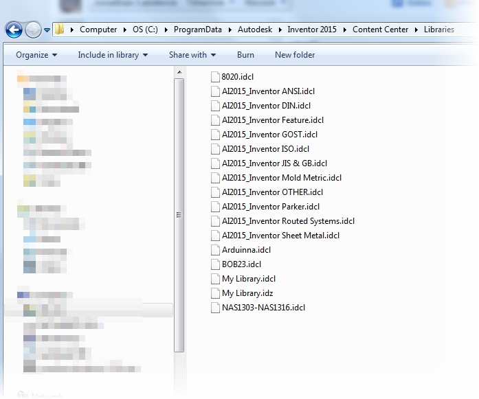
Example of the Desktop Content Libraries


The other, as Vault Content, where the libraries are stored with the Autodesk Vault databases. 

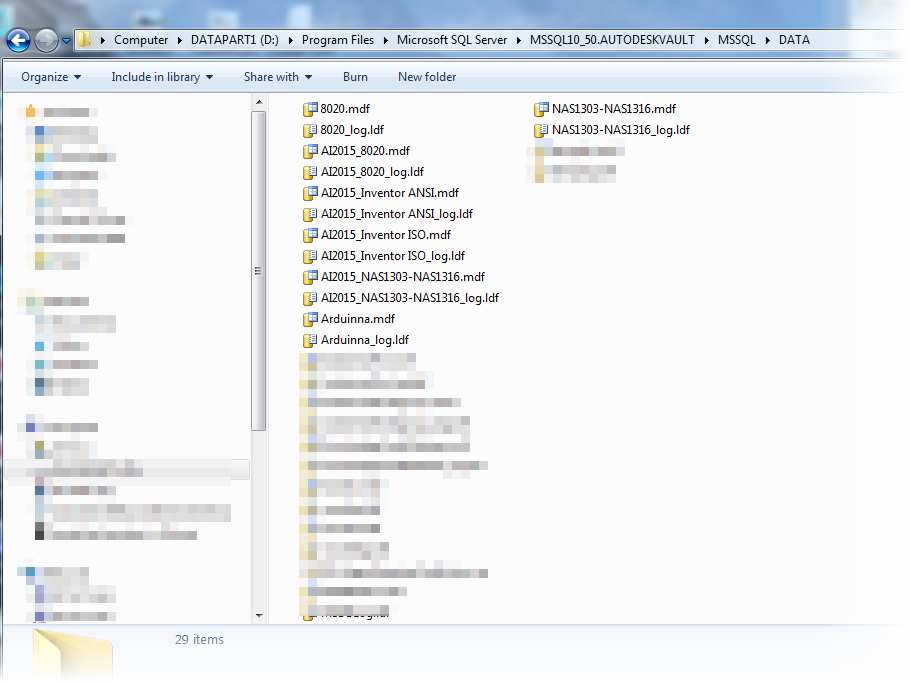
Example of the Autodesk Vault Content Libraries.
Note that not all libraries are installed here.


Regardless of how the Content Center is configured, it essentially functions in the following manner. 


  • User requests a component from the Content Center, by using Place from Content Center, for example.
  • Content Center will then check the folder where it publishes the data to see if the part has been previously created.  This location is set by either the Application Options, or by the Project, incidentally.
  • If it has, Content Center will place that component in the assembly
  • If it has not, Content Center will build that part, and place it in the assembly. 
So why would one be chosen over the other?

Vault Content is typically used when Vault is being used to manage data.  With the Content Center Libraries stored with Vault, they can be centrally managed with other Vault databases.  Also, and very importantly, the Custom Libraries can be backed up with the Vault backups, making sure all that critical is kept safe and sound.

The case for Desktop Content comes primarily when Vault isn't being used.  Vault Content requires the installation of the Autodesk Data Management Server (ADMS).  Using Desktop Content prevents having to do install ADMS just to run Content Center.

Another possibility is... Why choose one?  There are some users who will run Desktop Content event when running Autodesk Vault.  Why do this?  On its face, it may seem a bit backward. 

These users may be mobile users, who check out files from Vault, and leave the office.  They check out files, work on them, but don't check them in until they return to the office.  Having a copy of desktop content ensures that they can access content, even off site. 

Another reason is for users Content Center Administrators.  They may need to test content locally before publishing it to Vault Content.  Using Desktop Content provides a twofold benefit.

First, they can use Desktop Content as a "sandbox", testing configurations before they push them out to production.

Second, it can provide an additional backup. Should something happen to the Vault Content Library, the Desktop Content can be pushed to Vault without having to restore the entire Vault!   That can come in handy, and prevent having to restore an entire Vault to save content.

Imagine the downtime that could save. Just think about that a moment....  This is where I was really going with this post when I started it, way back about six inches up the page.

But with that said, how is it done?  

First, where Inventor is accessing it's Content Center Libraries can be selected in Tools>Application Options on the Content Center tab.

This can be done whenever needed, but in this case, I'm going to switch it now.  Why?  I intend to use the Desktop Content next, because I want to test a new configuration.

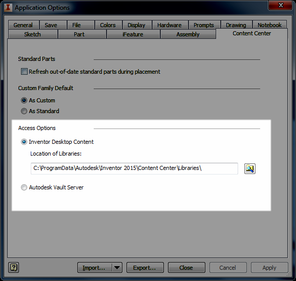
Selecting the location Inventor is pulling Content Center From
But this only tells Inventor where I'm accessing my libraries from.  It doesn't sync the libraries.  For that, there's a different step. 

Let's say, for the sake of my example, that I want to take a copy of Vault Content and transfer it to Desktop Content so I can test some changes before pushing them to Vault Content.  I also have several libraries in my Content Center so in this case, I'm going to work the the library containing NAS standard bolts, it's called NAS1303-NAS1316.  

To make the transfer, I go to the Get Started tab, and choose Projects

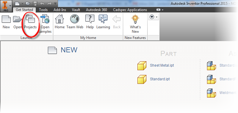
Locating the Project Icon

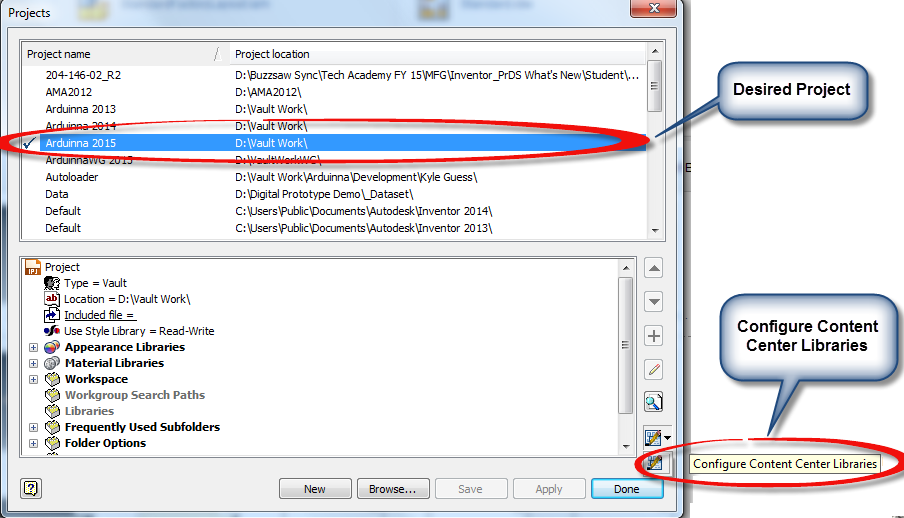
Now, once the project screen opens up, I need to choose "Configure Content Center Libraries" for the Content Center I'm working with. 

Selecting the Configure Content Center Library option


I can see where my content is currently being accessed from, and which are being used by this project. And from the bottom, I can choose the Library Transfer Guide, where I can transfer a library from the Vault Content to Desktop Content, or vice versa.

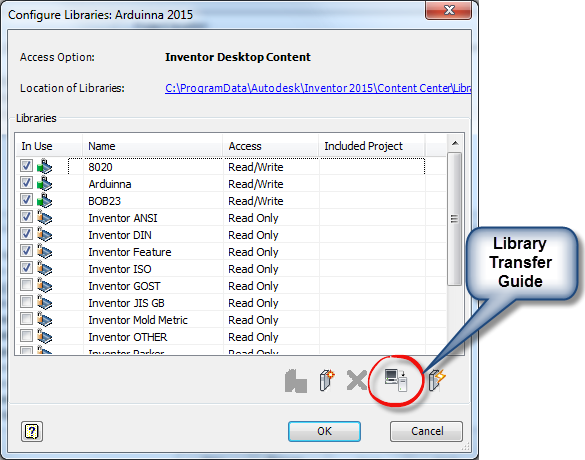
Selecting the LIbrary Transfer Guide


Selecting the Transfer Guide, I now get to choose which direction I want to transfer the libraries.  In this case I want to transfer from Vault Server to Desktop Content.  

Why?  It's my intention to transfer Vault Content to Desktop Content so I can work on it offline.  In the meantime, Vault Content can remain available to my users.

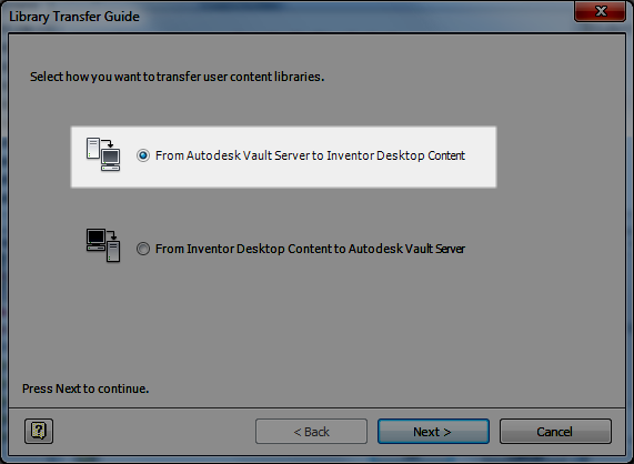
Choosing which direction to transfer the content


Choosing next, I can step to the next screen, I 'm asked to log into my Vault, which I do.
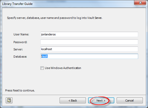
Logging into Vault

Now getting past this step, I go ahead and choose the library I'm transferring. Also note that the Custom Libraries at the destination are listed too. I chose my NAS1303-NAS1316 library, and click next.

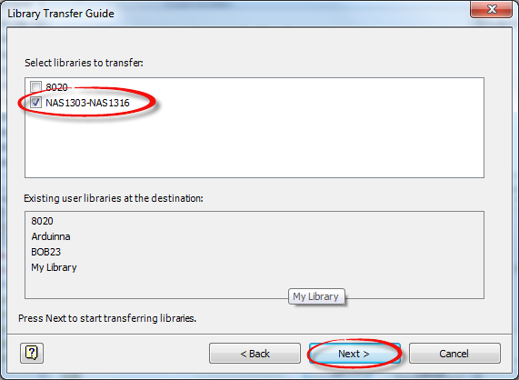
Choosing which library to transfer


The library will transfer, and after a few moments, depending on the size of the library, the process will complete.
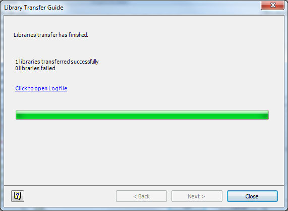
And we're done!

Now, I hit close.  On the next screen, I make sure to check the library I intend to work with.  Why?  I need to make sure it's available to this project, or else I can't edit it!


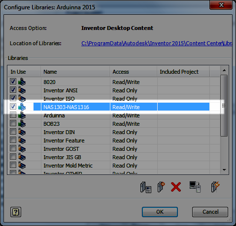
Making sure the library is available to the project

Now I can close all my screens, and if asked, save the project.  Now, I've accomplished two things.


  1. I've set Inventor to use Desktop Content
  2. I've transferred Vault Content to Desktop Content.


Now I can make changes to the library in Desktop Content, and test them while the content in my Vault Content is safe.

Once I'm happy with my results, I can transfer my Desktop Content to Vault Content by reversing the steps I've performed above.

 But there is one last thing to be aware of!  In order to make the transfer, the previous library occupying the space will need to be deleted! Why, the Library Transfer Guide can't overwrite content.  It's not difficult, but something that does need to be planned for.

Just make sure that the Vault is properly backed up, and that Custom Content was backed up with it.  If it's Desktop Content that needs to be backed up, just copy it to a new location, where it will be safe! And you're all ready to go!

Wow,  this was a long post!  But one I think was worth the time.  Take a look at it, and make good use of it!

And this isn't the only way this could be done.  Depending on configuration, and preference, there might be a few ways to approach this! Feel free to share if you have a different way of doing it!

And on a final note, for more information on editing content, check out my posts on that subject here!  There's a few, so follow the links!

And if you'd like the NAS libraries I used as an example, I've posted them to GrabCAD here!

***********************************************************************
Edit 13-July-2014 - Added Video to Accompany Text Post
***********************************************************************


Sunday, October 27, 2013

Triggering an iLogic Form when Placing a Component in an Assembly

“One person can trigger a million thoughts.”
Anonymous

Earlier this week, KETIV presented the Autodesk Manufacturing Academy.  As always, the event was fantastic, and I got to see a lot of fellow Inventor users, and friends as well.

One question that was posed during the session was: "Can I set up an iLogic trigger in such a way, that when I start a new file from a template, the iLogic form will show up automatically?" 

The short answer.... Yes!

Here's how it works.

First, the background.  I have a template for sizing a wooden board, and determining if it's got a tenon joint or not.  The parameters are driven by an iLogic form named "Board Options"


An example of the form and the board it drives

Since I place these parts in an assembly, and want to resize them, I want the dialog to pop up when I create a new component in an assembly when using this template.

I can't just trigger the dialog box directly, but what I can do is create a rule with a single line of code that opens the dialog box.   And I can trigger that rule to run when I start the assembly.

The first step is to create a rule, in this case I named it "Trigger Dialog", and add the following line:

iLogicForm.Show("Board Options")

An example of the iLogic rule with the required code.


This simple line will open the dialog box, but in order for everything to work as intended, one more thing is required.

An event trigger needs to be added by choosing the "Event Triggers" icon from the iLogic panel.  This is found on the Manage tab.

Set the Trigger Dialog rule to run when a new document is started. 

Setting up the Event Trigger


 Now, when the file is started from a template, the dialog box, fired by the rule, will open. 

And the resizing can begin!

P.S. If you'd like a copy of this file to take a look at, it's available on GrabCAD!  Click on this link!

Sunday, June 30, 2013

Conditional Feature Suppression in Autodesk Inventor - Turning a Feature On & Off Automatically

“Some have courage in pleasures, and some in pains: some in desires, and some in fears, and some are cowards under the same conditions.”
Socrates

Sometimes the challenge I encounter isn't knowing which tool in Autodesk Inventor to use, but which tool is best for a given situation.

For example.  Not that long ago, a challenge arose.  I had a part that was going to change size. 

When the size of the part changed, there was text that also needed to change to reflect the changing dimension of the part. 

Here I have an example I've created for this blog.  It's of a common wood working tool called a bench dog.

It's a pin, often (but not always) with a square head.  It slides into holes in the workbench and clamps boards from the side for working. 


Bench dog image courtesy Wikipedia


The head has dimensions of 1 inch square, and 1.5 inches square.  I've created text that will identify the bench dog.

The 1 inch bench dog
The 2 inch bench dog.  Different text, with a larger height is used.


Both the height of the text was going to change, and the text itself was going to change. 

I'm not savvy enough to get into the API and alter it using VBA.   But after reading Bob Van der Donck's blog here, I found a little inspiration. 

 Why not just create multiple features, and suppress them based on the dimension that was changing.  

Below is an example.  Notice that the 1 inch text is suppressed.  It only shows red on the part because I've selected it, and it's previewing for me. 

The "1 inch Bench Dog" text is suppressed.

For what I was doing, it would work! 

I could always us iLogic to suppress the features in question.  It's a simple enough operation for someone familiar with iLogic

But we wanted to avoid iLogic, so the parts could be kept as simple as possible, and could be reproduced by someone familiar with Inventor, but not necessarily iLogic.

And so the "brain-wracking" began.  How can I make this happen,without iLogic.

Then I had my AHA! moment.  Inventor has a tool called Conditional Feature Suppression

What does Conditional Feature Suppression do?  It suppresses a feature based on a dimension!

It's perfect for my case. 

My first step, was to rename the parameter defining the head size of the bench dog to "Dog_Width".  I also made this parameter a Multi-Value list with the values of 1.0 in and 1.5 in.

Creating the Multi-Value List


Adding the values to create the list.

The Mutli-Value list appears as a pulldown
 With the parameters created, I located the 1.0 inch text in the browser, right clicked, and chose Properties.


Accessing the dialog box for Conditional Feature Suppression
One the Properties dialog box opened, I checked the If check box, selected Dog_Width in the pull-down menu, and set the rule so the feature would suppress if the Parameter was anything other than 1 inch.

The options I've selected for the 1.0 inch text.


Now all I had to do was repeat the same steps for the 1.5 inch text, telling it to suppress if the Dog_Width parameter was not equal to 1.5 inches.


The settings for the 1.5 inch text.


And I'm done!  Editing the parameters and toggling between 1.0 inches and 1.5 inches will both change the size of the bench dog, and suppress and unsuppress the appropriate text!


Selecting the 1 inch face size:

Changing the dog.  Note that I've changed filters to shrink the parameters dialog

Selecting the 1.5 inch face size:
The 1.5 inch face.

So go ahead and take a look at Conditional Feature Suppression.  I know there are many out there who love iLogic, and will say that this could just as easily be accomplished with a few lines in an iLogic rule.


And that's true enough.  I'm not trying to say that iLogic isn't appropriate for this.

But what this gives is an option.  The ability to accomplish the same thing without using iLogic and sticking to tools that may be more familiar to the average user than iLogic.

Hey, there's no reason this couldn't be used in conjunction with other iLogic rules! 

So keep this in your bag of tricks.  It may prove helpful someday! 

And as always, check out the video version of this below!

Friday, April 05, 2013

Working for the Weekend & Going to the (Content) Library

“A library is a repository of medicine for the mind”
Greek proverb 

I'm occasionally asked where additional content center libraries can be found for Autodesk Inventor's Frame Generator, and it seems those are not easy things to come by.

I suspect that's because of the time involved in creating them, once someone invest the time to make one, they're reluctant to just give them away.   But do I know for sure?  No. I don't.

But a few weeks ago, I was walking the virtual isles of the file sharing site GrabCAD, and low and behold, what do I find?  Inventor Content Center Libraries for 8020 extrusion!  The files were created and uploaded by Stan Wile, and he deserves a big thanks for sharing the work he's created.

A sample of the extrusions use to create a frame. I've turned off one of the extrusions for clarity

The files are in *idcl (Inventor Desktop Content Library) format, and here's how they can be made available to your installation of Autodesk Inventor 2013.  Once those files are downloaded, it's time to get started.

First go to Tools>Application Options>Content Center Tab, and find the location where the Desktop Content Center is located.


The Content Library locations.

Now go to this location, and paste the *.idcl files into this location.  The other Desktop Content Libraries will be here.


The 8020 library placed into the Desktop Content Center location

But there are a couple of more steps before everything is ready to go.

The libraries have to be made available to the project using the libraries.  To start this step, go to the Application icon (I call this the "Big I"), and choose Manage>Projects

Navigating to the project file location


Once the Projects dialog box appears, click on the "Configure Content Center" icon at the lower right of the dialog box, just above the "Done" button.

Configuring the Content Center Libraries
Another dialog box comes up and the library can be added to this project by checking the box next to the 8020 library.

Adding the library to the project

Now, the 8020 extrusions can be used just like any frame generator component.

Using the new extrusions

If you want to download and add these extrusions to your own installation of Inventor, you can download them from GrabCAD by clicking here.  Yes, there is a membership required, but once you get into GrabCAD, I think you'll like a lot of the things it has to offer.

Also, if you're using a version of Inventor earlier than 2013, all is not lost.  Stan has also provided the 3D models of the profiles, which can be used to create your own Content Library by using the instructions at the Autodesk link here.

A Final Note

The libraries provided are for Inventor's Desktop Content.  If you're using Autodesk Vault, and wish to move the files to the Vault Content Center Libraries.  They can be transferred by using the Library Transfer Guide to be placed into the Vault Content Center Library.

Accessing the Library Transfer Guide


Tuesday, April 02, 2013

Using iLogic to Change Threads in Components... From the Assembly!

“Words form the thread on which we string our experiences.”
 Aldous Huxley

Not that long ago, I was tasked with a unique challenge. 

Trying to change threads using iLogic.  And while I knew it was possible, there was an additional twist. 

I had to do it from the assembly.   Now that's a way to add a wrinkle or two!

How do I change the threads in each component from the assembly?

 So I hit my favorite search engine, Google, and started surfing away.


And low and behold, I found my solution in the Autodesk Wikihelp, diving so deep I needed a diving bell. 

Torn from the Autodesk Wikihelp, the rule I need!

With a little testing, and verifying, I was quickly able to get this little gem to work.  The biggest thing I like about this version, is it allows for the changing to different thread types.  Such as from Metric, to Imperial. 

Using this method, I was able to set my threads from the assembly, without having to drill down into each part. 

In this example, I'm changing from a coarse thread to a fine thread, but with a little more work, I could expand this rule to do a lot more, and have it controlling much more than just coarse to fine.

Each "Feature.SetThread" command calls to the component in the following method:
"Bore :1"    ==>  This is the component being called out
"Threaded Hole"     ==>   This is the name of the feature being called
"ANSI Unified Screw Threads"         ==>   The thread type.  Basically, the tab in the Thread.xls chart.
"3/4-10 UNC"    ==>   The thread designation
"3B"   ==>   The thread class

Below is the full rule changing the threads for both the components in the assembly.

If Thread_Type = "Coarse" Then
'Callout for Bore
Feature.SetThread("Bore :1", "Threaded Hole", "ANSI Unified Screw Threads", "3/4-10 UNC", "3B")
'Callout for Shaft
Feature.SetThread("Shaft:1", "Threaded Shaft", "ANSI Unified Screw Threads", "3/4-10 UNC", "3A")

ElseIf Thread_Type = "Fine" Then
'Callout for Bore
Feature.SetThread("Bore :1", "Threaded Hole", "ANSI Unified Screw Threads", "3/4-16 UNF", "3B")
'Callout for Shaft
Feature.SetThread("Shaft:1", "Threaded Shaft", "ANSI Unified Screw Threads", "3/4-16 UNF", "3A")

End If


Now, with a multi-value list set in Parameters, I can use this small ilogic rule to change the threads for me!

Here's the rule setting coarse threads.  Notice the callout in the assembly browser.


The rule setting coarse threads

Now the rule is changing the threads to fine threads.  Now see how the callouts have changed to find in the assembly browser.


Now with fine threads, all changed by the rule.

That's it!  I hope you find this tip helpful!  And if you'd like to download the files I used in this example, you can download them from my Autodesk 360 site here!