Find us on Google+ Inventor Tales: Fusion 360
Showing posts with label Fusion 360. Show all posts

Monday, December 04, 2017

A 3D "Doodle" with Simulation in Fusion 360

A few days ago, an experienced engineer was explaining to us how changing the geometry of a component could affect the loads that it could have on how a part could handle the forces placed upon it.


Where the conversation started.
The representation of the mounting foot.

He explained that adding ribs to a mounting foot could greatly change how the mounting foot absorbed the loads, making for a more durable part. 

The modified part with ribs encompassing
the mounting hole.
So on this night I decided to build two parts pictured above,  and applied the same load of 1500 psi to them using Fusion 360.  I thought it would be a good exercise, and an opportunity to validate what I had learned.

The hole diameters and positions are the same, as well as the face bearing the load. 

After fixing the parts in the same place, I ran a simulation to see what would happen.

And the results of these quick tests was pretty interesting!

The ribbed foot had a much higher safety factor than the non-ribbed part.

The two parts next to each other.
The difference 
It was a nice exercise and validation of a concept.  And it was nice to have Fusion 360's simulation capabilities to be able to quickly test out an idea and quantify it.

Best part is now I have these parts for reference later!

It's just like a 3D note!

And finally, if you'd like to download the parts I created, you can find them here and here!

Sunday, November 26, 2017

A Quick Tip on Creating a New Drawing in Fusion 360

The Thanksgiving Holiday here in the United States and some studying for a class have been keeping me busy, but I've been starting to get a little seat time creating drawings in Fusion 360 for a wooden rack I've been working on.  
The Fabric Rack in it's current state.
There's still some adjusting to be done! 
The tip I'll share is a simple one, but one that not everyone may realize is there.  

I know I haven't been using this tool nearly as much as I should have! 

If you right click on a component in the model tree, you can create a drawing for that component by choosing Create Drawing

Creating a drawing from the model.


Choosing that option, a dialog box appears that gives the following options. 

1. Create a drawing of the full assembly found in the model, or just selected components in the model. 
The first step to creating a drawing

2. Create a new drawing from the selected component(s), or add a component to an existing drawing. 

3. Choose a template drawing or start from scratch. 

4. Choose to use the ASME or ISO drawing standard.

5. Choose the default units for the drawing.

6. And finally, choose the sheet size for the drawing.  

Once you hit OK, the drawing will generate and you'll the opportunity to place the views on the darwing.  These options include

1. View Orientation

2. View Style, such as Visible Edges, Visible and Hidden Edges, Shaded, or Shaded with Hidden Edges.

3. Scale so you can size the view to the page.

4. Tangent Style, which include Full Length, Foreshortened, and Off. 

5. Toggle Interference Edges on or off. 

6. Toggle thread display on or off.

I found it can be a slick way of creating a view, some of which I'm still testing out!  But I think it's well worth taking a deeper look!  

I'll keep you posted! 


Monday, November 13, 2017

Using Your Resources to Design in Fusion 360

I've had a mental idea to build a simple rack to hold bolts of fabric in Fusion 360. 

It would look similar to this mobile pipe rack found on the McMaster Carr Website

But naturally, the store bought version doesn't quite meet my needs.  Murphy's Law wouldn't allow that!  So that leaves me in the position of designing and building one. 

Here's one side of the rack, mostly done,

And seeing how I don't want to work on it evening upon evening, that means I have to take advantage of every step I can to increase the efficiency my design time.

Now I should mention that many of these steps I've shared before, so this will be a link back to these posts.  But I think it's a good example of how these processes can come together and become greater than the sum of their parts. 

Here are the tips!

1) Don't Create a Model if You Don't Have to!

The rack needs to be mobile, so it needs to rest on casters.  Fortunately, Fusion 360 has a link to the McMaster Carr website that lets you insert models from their website into your design.  The part number is included, so you can always order the part from McMaster Car if you like.

Downloading these casters was more accurate and less time
consuming than trying to build my own versions

Here's the link to a previous post if you want to read more!

2) If you have to build it, reuse it! 


Every wooden piece pictured here was built and resized from
one source model.

The frame is going to be made primarily of 2x4s.  And while this isn't a complicated part, why keep drawing rectangles over and over again if you can just Copy and Paste New?  This tool allows you to copy a part, paste a new, independent version, then resize and reposition it where needed.

You can find a link to more details there. 

3) Don't rebuild what you don't have to! Redux!

I couldn't find the joist hangar on the McMaster Carr website.  It might be their, but I couldn't find it.  So instead I tried GrabCAD and found it here.

The joist hanger inserted into the model.


The download wasn't quite as slick as the one on the McMaster Carr website, but it was still a lot quicker than building the model myself. 

In Conclusion!

The design still has a long way to go.  It's not even complete, and I can already see a few changes I'll probably want to make.  But being able to reuse and download parts got me a lot further down the road in a couple of hours than I otherwise would have been.

So I hope these ideas inspire you to try a few things, and get a little further down the road yourself!

Tuesday, November 07, 2017

Lessons from Life's Workbench - Selecting a Solid Rivet

In my last Wednesday, I talked briefly about how rivets are sized.  But what about how to choose a rivet for a given application?

There are requirements for how to select a solid rivet, and while they may vary slightly from application from application, the FAA publication AC43-13-1B is a good guideline for selecting a solid rivet.

The pages referenced are 4-20 and 4-21, and can be downloaded at this link.

So what do those instructions tell us?

For my example, I'm going say I'm riveting one sheet of .032 thick material to .040 thick material, using a MS20470 "universal", or button head rivet.   
The Sheet Metal Thicknesses shown
in red and cyan.  The rivet is in gold
The first step to choosing a rivet is to select a rivet diameter.  By referencing the document, you can see that it states that we should use a rivet with a diameter 3 times the thickness of the thickest sheet.  

So if the material is .040 thick, then 3 times that thickness is .120, which is close enough to a 1/8th (.125) inch rivet.  

So there we go!  The diameter is selected!  But now, how long of a rivet do we need?

The dimensions of the rivet needed for this application.
AC43.13-1B states that we should use a rivet that extends 1.5 times its diameter beyond the underside of the material.  

Adding .032 and .040 we end up with a total material thickness of 0.072.  Extending 1.5 rivet diameters beyond that we get a total length of .2595 inches,
which is close enough to 1/4 (.250) inches.

So this application calls for using a MS20470-4-4 for this particular application.

Now the rivet can be driven with a rivet gun and bucking bar, and the parts can be fastened! 

A typical rivet gun and bucking bar set.


I hope you find this tip helpful!  

A sample of the approximate dimensions of the set head.
One final note, the documentation I've used is an "Advisory Circular".  If you have engineering documentation, such as a manufacturer drawing or a maintenance manual, do what it says!  The manufacturer's data always wins in this case!

Sunday, October 29, 2017

Placing an Assembly into a New Design in Fusion 360

Last week I talked about how I used the Paste New functionality in Fusion 360 to quickly create a continuous hinge. 

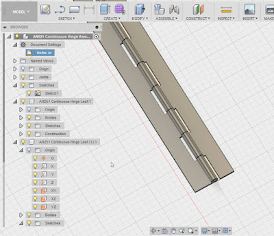
A close up of the continuous hinge as it was finished in my previous post. 
My goal in creating this hinge, was to use it as a template so I can reuse it later.  However the thing with continuous hinges is that they're cut to size.  So even though the original hinge stock starts out 36 inches long, it can, it is often cut down to a much shorter length.

So what I'd like to do is insert the hinge into an assembly and cut the hinge to the length needed for that particular application.

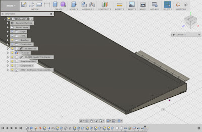
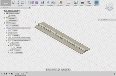
The finished hinge placed into position.

I started out with my target assembly opened and saved.  For the sake of keeping the example simple, I'm going to use an empty file for the target assembly, but the steps are the same if there are other components already placed.

Now, I locate the hinge I intend to use in my data pane, right click on it, and choose "Insert into Current Design".

That will insert the file into the current design. 


The next thing I have to do is cut the assembly to size.  This required me to break the link with the template, so I can make the part independent from its parent. 

I can do this by right clicking on the part in the browser and choosing "Break Link". 

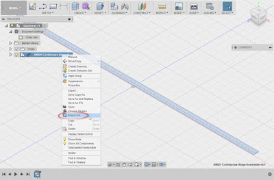
Breaking the link to the original hinge.
Now it comes time to cut the part down to size.  Naturally, this may vary for different parts.  In the case of the hinge, I used an offset work plane to split the solid bodies that make up each hinge leaf.

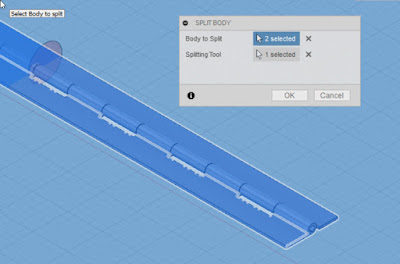
Splitting the hinge leaves using the split tool and a workplane.  The workplane is
off screen (it's why the background is blue). 
Now each hinge leaf is split into two bodies, which can be removed from the model using the "Remove" tool.  You'll have to locate the bodies underneath each component.  I've numbered them in the image below.


Hint!  Don't use the delete tool!  It can cause your features to blow up!

But now, with the hinge sized, it can be positioned as needed in its new home!

The hinge is completed!
In conclusion!

Personally, I like how this workflow allowed me to take an assembly, place it, and modify it quickly.  I can cut the hinge down, add holes, all without harming the original. 

I'm particularly pleased with how I can contain the hinge in a single design, and not create three separate files (two parts and an assembly).

I do feel a few pangs of guilt about breaking the link to the parent, since if the parent changes, the hinge derived into this assembly won't be updated.  But for the most part, standard parts such as this don't change often, so I think I can live with that possibility. 

All in all, I think there is much more to be gained with this flexibility!


Sunday, October 22, 2017

Using Fusion 360's "Paste New" to create Similar Parts

Before diving into my next post, I wanted to say that I'm glad the solution I shared to fix the broken threads issue in Autodesk Inventor helped so many.  When it first occurred earlier this week, I thought it was just me.  Little did I know that so many others would run into it!

I originally found the issue on the Autodesk Community, so credit where credit is due.  The link to the post where I found the information is in the original post, as well as linked here.

Now, I'm back to a little Fusion 360 work I've been doing.

As part of an ongoing project, I've been slowly building different parts here and there, mostly off of vintage prints from AirCorps Library

One of the challenges I ran into was building a model of a continuous, or piano hinge.  It's based on the AN951 standard, which has since been superseded by the MS20257 standard,

One hinge leaf.  A little examination shows how it's mate has to
vary to mesh correctly.

Modeling the hinge isn't a difficult task, building the individual hinge leaves is easy, but they need to be made to mesh correctly.   That means the hinge knuckles have to be offset, and that's where the knuckles have to be different.


But other than that, everything is the same only the hinge knuckles vary.  So it would be ideal to be able to create a new copy of the existing hinge leaf, and make the appropriate changes. 

It turns out that Fusion 360 has a functionality known as "Paste New", and it's exactly what I needed.  It will create a new, independent copy of first hinge leaf, while leaving the original alone.  That means being able to reuse as much of the design as possible, while only changing what has to be changed.

I started with an assembly with one of the leaves modeled as its own component.  You can see that in the browser..  Now it's time to make the other side of the hinge so it can be changed so it can mesh with its mating hinge leaf.
The browser with the new part modeled
 All that needs to be done is to right click on the existing component and choose "Copy".  It's just a good old Windows Copy.

Copying the part is where it all starts. 
Now move the cursor onto the modeling canvas, right click, and choose "Paste New".  A new, independent, hinge leaf can be placed and positioned. 

Pasting the new copy using the Paste New command
I'd suggest getting the part as positioned in it's "nearly" correct position.  Then you'll be able to make changes to key features, the hinge knuckles in this case.

Positioning the part. You can use the handles, or dialog box.
Now all that's left to do is activate the new copy, modify it so it meshes with the original, and assemble.  And we're off to the races!

There it is!  All done! 

So keep this in mind when you have similar components to build, and modify it for your needs.  It can really help in not recreating extra work!

Tuesday, September 26, 2017

Coast Fabrication - A Great Source for Fastener Information!

A sample of a Hydraulic coupling rendered in Fusion 360
In this post, I'm actually taking a step back from directly talking about a design tool.  Instead, I'm sharing a little info on where I get the information to put my design tools

At work, one of my tasks is creating and maintaining Autodesk Inventor Content of aerospace fasteners.

And trust me, there are a lot of these fasteners around!

They can be referred to as AN (Army/Navy), MS (Mil Spec), NAS or NASM (National Aerospace Standard), and AS (SAE Aerospace).   And I'm sure I've missed a standard or two somewhere! 

That means a lot searching databases, reading charts, and sifting through a lot of tables!  

Of course that begs a big question?  Where can this data be found?  

Admittedly, it can be quite a safari.  I'm fortunate that my place of employment maintains a resource for the data.  

But not all of us have that luxury.  That means a lot of hunting around, trying to find the data we need.  

One resource I found that has been a enormous help has been the technical resource page from Coast Fabrication in Huntington Beach, California

More than once I've used their technical page as a quick reference for a fastener I'm using, sometimes for work but other times for personal use.  

This is just a section of the Coast Fabrication Technical page


The reason I shared this site is because I know that there are many times users need this information.  It might be to create a library of helical inserts for work, or a quick model of a hydraulic fitting for a personal project, this is a sight that is well worth the reference!

Of course, a blog post like this wouldn't be a blog post if I didn't have a disclaimer.  I'm not paid by Coast Fabrication.  I've never even visited their shop even though their only about 10 miles away from me. As a matter of fact, I'm pretty sure they don't even know I exist.  

But that's okay!  They've provided a great resource worthy of sharing, and I'm happy to help Karma return some of their goodwill!  So take a look if you're in the need for fastener specs.  


Monday, September 18, 2017

Easing selections using the "Select Other" tool in Fusion 360

In my last post, I mentioned changing the opacity of a part in Fusion 360.  The intention was to make it easier to transfer geometry from one part to another. 


This part is giving me a lot of mileage! 
I also mentioned that it can make it easier to select a part laying underneath another.

But the reality is I only told a part of the story.  Just being able to see an underlying part, step two is being able to use that part's geometry.

Three holes to be projected.
For example, if I want to transfer the holes from the ribs to the skin of the tab, I can activate the sketch in the skin, and project geometry from the rib to the skin of the tab using the Project tool.

The Project tool is your friend!

But those are some tiny holes under some thin sheet metal!  That means that I only have a small target to hit with my cursor, with lots of other geometry that can get in my way.

The trick, with Project tool active, left click and hold the left mouse button down.  After a moment, a list of geometry that can be projected will appear.

The options to select various geometry.
Just choose from the list!


All that's needed is to choose the desired geometry from the list.  The geometry, in this case a hole, can be used to create the needed cutout.

Extruding the projected geometry
So give select other a try.  And it's not just for sketches.  It can be used any time selecting from multiple pieces of geometry is needed!


Sunday, September 17, 2017

Creating a Part by Projecting Geometry from Another Part in Fusion 360

One of the goals I set  for myself is to try to spend some time every week to build something in Fusion 360.  Sometimes, all I can do is create a patter of holes, or build a few sheet metal flanges.

But I always tell myself I'll try something new in Fusion 360.  

So far, so good!

One thing I've been trying is making different parts, some of which have been sheet metal.

I've got ribs that will support a sheet metal.  The component is an aircraft trim tab.  There are two ribs at each end of the tab.

The sheet metal forming the tab will wrap around the ribs and attached via rivets.  That means that the sheet metal will be following the ribs, so why not reuse that geometry instead of trying to recreating with a lot of "measuring and calculating".

The first thing to do is to assemble the ribs in their final position and orientation.

The ribs place and oriented, ready for sheet metal.
The next step is to create a new component in the Fusion assembly and activate it.  Select it as a sheet metal part and set your sheet metal rules.

If your not sure about creating sheet metal rules, my previous post here may help.


Create a new component

Now, create a sketch, and being projecting geometry from the existing parts.  


Now project the geometry that will be used to help define the new part.  I'd recommend making it construction geometry to make sure it doesn't accidentally add itself to your part. 

Creating construction geometry to build a part.
Now sketch out the profile required.  In this case, it's the shape of the sheet metal part. 

Projected geometry to form the sheet metal profile.

Now it's a matter of creating the sheet metal flanges to the distance needed to define the part.

The sheet metal part extruded.
Now continue the process of defining the part.  This includes other features, such as extrusions and holes.

Additional features can be created by projecting from another part.
Give it a try, it can make creating another part much easier than transitioning measurements! 

Bonus tip! 

Change your part opacity by right clicking on a component and choosing "Opacity Control".  You can make the part semi-transparent and make it easier to see underlying geometry! 

Try changing Opacity to make selecting through parts easier.
Acknowledgements: 

Trim tab created from drawings accessed via my subscription to Air Corps Library.

Thursday, August 31, 2017

I've Got Great Designs in Fusion 360! But How Do I Find Them?

A valve housing I built, I'd hate to lose this! 
Lately, I've been posting about building models in Fusion 360, especially with the addition of sheet metal tools.  (Yay!)

But the most stunning Fusion 360 file in the history of stunning Fusion 360 files does no good if you're not able to locate it in the sea of slightly less stunning Fusion 360 files.

As I've started accumulating models, I found myself thinking; "How to I find a given file as I create more designs?" or, "What happens, if I misplace one?!?"

I haven't yet misplaced a file yet.  But it will happen some day, and I'll have to make sure I can find it again when I do.

Thus, I was led to the Data Management side of Fusion 360, to try a little simple searching.

The first thing I had to do was log into my A360 hub here.  That opens up the A360 hub, where I was greeted with a list of the projects I've created over my time using Fusion 360.

From there, it was a fairly simple matter of locating the search icon, typing in a file name, and letting the search tools do their job.

In my case, I picked a valve housing I had worked on.

Searching for the housing


When the file opened in my dashboard, I could see a thumbnail, what other designs this housing used, and where this file was used.  In my case, I'm not yet using this design elsewhere.  I can also access drawings created from this part.


Now there's quite a bit that can be done from this screen, so I'm not going to go into it all in this post. I'd be typing forever!

But I will point out two icons that are well worth looking at.

The first, is the View icon, which will open up the file in a viewer, the other is the Edit icon, which will open the file in Fusion 360 desktop, and the browser if available.


Just these functions alone helped as I was exploring alone, and there are more functions in the viewer. But like I said, I'm going to save those for later!  It's getting late, and I have to sleep sometime.


But remember to take advantage of the hub if you're using Fusion 360!

I think it'll help you out!