Find us on Google+ Inventor Tales

Wednesday, June 24, 2009

A 'Component' by any Other Name

Fate tried to conceal him by naming him Smith. ~Oliver Wendell Holmes, Jr.

Today I returned to Inventor today after spending some serious time with Autodesk Showcase. I'll be returning to Showcase soon. I've been on a mission to create some more renderings for the website (www.ketivtech.com)

But today I was asked a question that forced me to hunt around a bit.

"How do I change the names of Assembly Browser nodes?"

Here's an example of what the Browser Nodes are. When the files are initially created. The nodes inherit the file name of the component when it was created.


(Click to Enlarge)

I've run across this before. This time, I got that little light bulb in my head that said 'it's in there somewhere'.

So what did I do? I did what any good techie would do. I dove into Inventor (taking a moment to scoff at the instructions), and began clicking through tabs furiously, convinced that my expertise would help me locate the tool in no time.

About fifteen minutes and grumbling incoherently at my machine. I broke down and hit 'F1'.

With the help of the appropriately named Help system. I found what I was looking for in no time. A tool named 'Rename Browser Nodes'

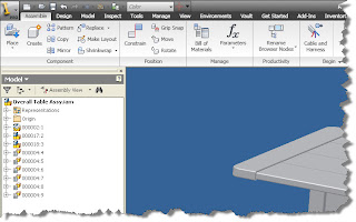
It's located on your Assembly Ribbon, under the Productivity Section. Click the arrow in the lower right hand side of the button to see all the tools.


(Click to Enlarge)


(Click to Enlarge)

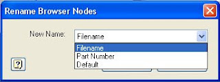
Once you get the tool. You'll be able to rename the Browser Nodes to the Default (the original name). Filename (the filename, including the extension), and the Part Number (which will insert the Part Number iProperty).


(Click to Enlarge)

For example, I'm going to rename my browser nodes with the Part Number.

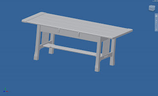
The assembly I'm going to use is a Craftsman style table I built as a project (my feet are resting on it as I type this). I modeled it in Inventor, created the drawings, and also used Producstream (now Vault Manufacturing) to create the a part numbers.


(Click to Enlarge)

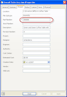
The numbering sequence is simple. It starts from 000001 and increases from there. No special numbers for assemblies, subassemblies etc. Here's an example of one of the part numbers


(Click to Enlarge)

In any case, all I want to do is renumber the browser nodes with my part numbers.

So.... You guessed it. I just choose 'Part Numbers' from the Window above.

With that done, my browser goes from this:


(Click to Enlarge)

To this:


(Click to Enlarge)


Once you know where it is, it's not really all that difficult. If you need to switch it again, just repeat the steps, and choose a new option!

Well, that's it, back to Showcase for a while!


Sunday, June 21, 2009

Lighting the Mood. Autodesk Showcase Lighting

Firelight will not let you read fine stories but it's warm and you won't see the dust on the floor. ~Irish Proverb

As I've been working with Showcase, I've started to try different things to see what effects they would have on the scene I was working on.

One of these was lighting, and particularly the color of lighting can have on a scene. I don't profess myself to be some sort of lighting expert, but here's some of the things I've learned from other users, and by poking around after saying 'I dunno, let's try it!"

By default, the colors of your lighting is white. For many scenes, that will be sufficient. But just like you can create an effect and impression, changing the light colors can add some nice touches.

One thing I've done is look a photos for inspiration. Here's an example of a picture I took at the Planes of Fame Museum in Chino, near my home in Southern California.

This F-86 Sabre is parked indoors, so it's lit mostly via skylights that let in natural light, but tint it slightly yellow.

But the tail is catching the natural light coming in through the open hangar doors, which is more of a natural white.


(Click to Enlarge)

You can use the lighting in Autodesk Showcase to simulate similar effects.

Here's a scene where I've used a personal computer in the 'Desert Dawn' environment (hey, don't we all keep our computers on desert roads?).

But this scene has a lot of red and blue hues in it, so it shows how the lighting can affect the look of a scene.

In this first picture, I've used all white lights. You can see how the computer looks 'bright' compared to the rest of the scene. Almost like it's been lit by an artificial light source. This is fine, it does make the the lit object standout (which may be the desired effect).


(Click to Enlarge)

There are currently two lights, one in front of the computer, and one in the back of the computer. For what I'm doing here, I won't change the lighting position at all, just the color.


(Click to Enlarge)

But what happens if we start changing the colors of the lighting?

If I choose one of my lights, right click, and choose 'Properties', I can start to change the properties of my lighting. There's a lot of settings, but for now, I'll just focus on color.


(Click to Enlarge)

Once you choose properties, you'll see the light properties come up, you can click on the button that affects the color, bringing up the color screen.

With the color screen up, you can click on either the wheel, or the scale. Both will let you change the color of the light in their own ways.


(Click to Enlarge)


Now, I'm going to change the lighting properties of the light, and give it a red tone. Notice how the image looks different, it's a 'warmer' (at least that's my term for it) light.


(Click to Enlarge)


(Click to Enlarge)


Now giving the back light a blue hue.


(Click to Enlarge)


(Click to Enlarge)

Finally, you can change multiple lights, and see the effects. Here I've changed the front light to a red hue, leaving the blue light alone.


(Click to Enlarge)


The effect is pretty dramatic. Personally, I'd keep one of the white lights in there because the original color of the case (white) has been lost. But in many cases, it's about what your audience finds compelling.

That's it for now. Don't be afraid to experiment a little bit. You can always change the colors back!

On a parting note, here's a couple of more pictures I took of a Grumman Duck. Here you can see how the natural light coming in from the front hits the nose of the plane, highlighting the front of the airplane.

The natural light filtered by the skylights hit the rear of the plane (similar to the F-86 Sabre). You can also see in the different pictures where the lights come from (The windows in one picture, the skylights in the other).

I've found if I keep things like this in mind, it helps give me ideas on what to do with lighting to create better renderings in the future.

Besides, it gives me an excuse to run off to Planes of Fame and take pictures of cool old airplanes!


Natural light from front, you can even see some fill from the flash on the float (Click to Enlarge).


Filtered light from the skylights fills in the background. Notice how it interacts with the natural light hitting the front of the plane. I look at images like this to get ideas on how to place lights in Showcase.


Happy Monday all!

Wednesday, June 17, 2009

Showing Off in the (Autodesk) Showcase

“Life is a series of experiences, each of which makes us bigger, even though it is hard to realize this. For the world was built to develop character, and we must learn that the setbacks and grieves which we endure help us in our marching onward.”

~ Henry Ford

I've got to admit that I've been on a bit of a hiatus on blogging with Showcase lately, but I've been nose to the grindstone creating renderings for several of our customers. You can see them scattered throughout the KETIV website. The renderings I used were either STEP or Inventor Models, but you can also use files from other 3D CAD sytems. I'm hoping I can branch out here now!

I have to admit that there were times that I had to walk away from my laptop, frustrated by the fact that I couldn't 'quite get it right'. But with some help and encouragement from some of the Showcase guys at Autodesk, I was able to get some of the tricks handled.

One thing I had to learn to do was to 'quit thinking with my engineering brain'. With that linear thought process disabled, I started trying things that I didn't think would make a difference.

And to my surprise, these little things made the renderings 'pop'. In other words, the reactions to the renderings when from 'that's cool' to 'wow, that's pretty cool'. With the appropriate effect on my ego. :-)

The tricks I want to share is the use of the Tilt, Perspective, and Height options. They change the camera angle and perspective that the rendering is being viewed at.

(Click to Enlarge)

Each tool brings up a slider that will adjust the camera angle and perspective.

The first example, is changing the Perspective.


(Click to enlarge).

Here's my first picture, with a perspective setting of 50mm. Special thanks to Castor Engineering Inc for providing data for rendering.
'

(Click to Enlarge)

Now with the slider moved toward 'Wide Angle' and a focal length of 27mm. Note, this is the only thing I've changed.


(Click to Enlarge)

Here's an example of changing the Tilt from the default.


First using the default Tilt angle of 0 degrees. Thanks to California Analytical Instruments for the models for these renderings.


(Click to Enlarge)

Now with a Tilt of -11 degrees. Just like with the Perspective before, this is the only thing I changed was tilt from one image to the next.


Lastly, is the height. Of all of the three, I probably have used this the least. But it is a good way of playing with high and low camera angles.


Thanks to Datum3 for providing the model used for this rendering!

First, the default, which is 160cm.

(Click to Enlarge)

Next, with the Height changed to 52 cm.


(Click to Enlarge)

You can see how something that at first can seem almost trivial can make a huge difference, and I only used each individually, just think what you can do if you combine the effects!

On one last note, don't forget it's all about making a rendering that captures people's attention, and ideally, draws them in. So there isn't some sort of formula that you can type in "X+y/Z" and get "Compelling Rendering". But just these little things can go a long way to making something that will make someone stop and stare.

And that's always fun!

Monday, June 15, 2009

Putting it in the Correct Folder. Inventor R2010

One of the new features in Inventor R2010 that seems to be getting 'lost in the noise' are the new Assembly Folders.

There are plenty of good features that have come in the new version, and while they deserve their accolades, I don't think Assembly Folders are getting their due.

So, what exactly is an Assembly Folder?

In short, an Assembly Folder is just a folder that's created in the assembly browser. You can place components in this folder and gather up similar components in that folder. It reduces the components sitting at the top level of your assembly level browser, and makes for a cleaner and easier to navigate interface.

Here's an example where I'm starting to use them.

I've a woodshop project that I built a few years ago (a Craftsman style table). If you look at the screen capture, you can see that I have several screws that take up more real estate in my browser than the subassemblies that make up the table.


I'm going to place the screws in a folder called 'Hardware' and collect them in that folder.

The first step is to right click in the assembly browser. You'll see an option to 'Create New Folder'.


Choose 'Create New Folder' and a folder will appear in the browser, and its name will activate, allowing you to rename in. In this case, I've called it 'Fasteners', although you could name it anything.

Now you can just drag and drop the components you want (in my case the fasteners) into the folder. Once this is done, you can see how this cleans up the browser.

If you need to access the parts, you can still expand the folder, and expose the components inside the assembly folder. Once you see them, you can access them just like you did before!


Happy Monday everyone!

Thursday, June 11, 2009

Importing a Rhino (file into Inventor that is).

Here's a quick announcement for something coming out of Autodesk Labs! There's a new import tool for Rhino (*.3dm) files now!

You can download it from Autodesk labs HERE!

I haven't had a chance to use it yet, but if anyone has any Rhino files they're willing to share, I'd love to test it on some real world files. Let me know if you have something to share with a comment!

Happy Inventing everyone!

Wednesday, June 10, 2009

Autodesk Assistance Program... Did you know?

"It's a sign of the Times." We've been hearing it everywhere. I've even said it myself.

There are rumblings about what's hopefully a recovery beginning. Whether we're really seeing it or not is a subject of debate, and I certainly have no crystal ball.

So why am I blogging about this? There's no Inventor Tip, Showcase Tip, story of a trial or tribulation about Vault or iLogic in it.

It's to mention that Autodesk expanded the Autodesk Assistance Program.

If you don't know what the Assistance Program is, it's a program where displaced workers can get assistance with training, free educational licenses of Autodesk software, in order to develop and maintain their skill sets so they have more to offer on their resume in their continuing job search. (More on that HERE)

Today Autodesk announced that they've expanded the program (Click HERE for the press release describing all the benefits).

There's new e-learning offerings avaiable now, and even companies can benefit with reduced cost software when they hire someone who's participated in the program.

Hopefully, you don't need this program (and by 'not needing it' means you're working), but if you are one of those who are looking for work, here's one way to stand out to anyone who's looking to hire.

Good luck out there everyone!

Monday, June 08, 2009

Land of the Lost (Browser)

If you've been using Inventor any length of time, you've had it happen.

One slip of the mouse and POOF! You're feature browser disappears.


In the older versions, it was just a matter of going to View>Toolbars, and checking the appropriate check box.


But now we're using Inventor R2010 and the new interface, and such a thing doesn't exist anymore.

SO WHERE IS IT?

It's not really that hard to find, once you know where to look, but then again, what isn't? Here's where it is in the new interface.

Got to your 'View' tab and click on the 'User Interface' Button. A fly out will expand and give you a check box for several common items, one of which being the interface.

Click the Browser option, and your browser is back and you're back in business!


Happy Monday everyone! I hope this tip helps start off a good week!

Tuesday, June 02, 2009

Default Inventor Settings... That's Great! How Do I Change It?

I've often mentioned how there are certain things I change as soon as I install my new seat of Inventor. I've done this for as many releases as I can remember, and while not everyone likes my settings, many a user has thanked me for my input, and adopted one of my suggestions.


So after far too long, here's the settings that I change in a part.

You can find them under Tools>Application Options, on the Sketch Tab.

1) Grids - I don't like the clutter of the grids. I leave the axis, because I like the fact that seeing the axis leave me with feedback letting me know when a sketch is active.

2) Edit Dimension When Placed - The default requires an extra click to edit the dimension. I check it so the dialog pops up when I place it.

3) Project Origin on Sketch Create - The default doesn't create a point on origin. I like to constrain to origin myself (must be a holdover from my days at the tool and die shop). So I check this one too.

I've included a Youtube video that shows me changing the steps as well. Feel free to follow the link HERE!

Sunday, May 31, 2009

Inventor R2009 and Vault 2010

I'm currently in the process of coming up with some more blog topics, and hopefully a video or two, but this weekend was spent hanging out with some good friends at an art show, so not much blogging got done! (Hey, even geeks have a life!)

But here's a quick tip for those of us who are working with Inventor, and Vault.

Note that there's one for Inventor R2009 Service Pack 1, and Inventor R2009 Service Pack 2.

One last note! If you've installed the Bonus Packs from the subscription site, make sure you download the service pack for thue Bonus Pack!

Once those are installed, everything should be running just fine!

Happy Inventing!

Friday, May 22, 2009

Once Slice (Graphics) at a Time.

Earlier in the week, I was working with some users. and on a fluke, I showed the 'Slice Graphics' tool.

I was surprised at how few of the users knew it was there. After all, I've known about it since I started on Inventor back on Release 4, right?

It was certainly not the fault of the users. They were experienced users who had been using all manner of CAD software for years.

How did they miss it? They had never known to look for it, and nobody had thought to show them.

A classic the users who know it assume everyone knows it, and the users who don't know it, don't know to look for it.

So without further delay, here's where the slice graphics tool is.

First you'll need to be in a part file, and have a sketch active.

Here I've got a part athat I'm going to create a groove on the inside face. I've already created a sketch plane down the middle of the part.


You can already see that the sketch plane runs through the middle of the part, and that trying to sketch the groove is going to be tricky.

I could switch to a wireframe view, but that's not really the point of the exercise! Aside from that, it may not always grant you the detail you need.

So instead, while the sketch is active, I'm going to right click, and choose 'Slice Graphics' from the context menu. Remember that if you don't see the option come up, make sure you don't have any geometry active, or that there isn't a tool (like dimension) still active.

Also note that the hot key for this is 'F7'


Choose the selection, and the part will be 'virtually' cut. Inventor doesn't actually cut the material away, it's purely a graphical. But it does let you see the inside of the part you're working on.


Now, you can use the 'Project Cut Edges' tool to project the silhouette of the part onto your sketch plane.

You'll find it on the Sketch Tab, indicated below. Notice the projected edges already shown below.


Now sketching, dimensioning, and constraining is conducted the same as you would in any other sketch.


In this case, we finish with a Revolve. And our groove is created. The slice will automatically 'Turn off' when the revolution is complete.


And that's it! Happy Inventing! Happy Memorial Day!

And thanks to Dad for all the years as air crew in the Navy. You earned that retirement.

Tuesday, May 19, 2009

New from the (Autodesk) Labs

Just a quick blog to show that Autodesk issued a new iCopy tool for on Autodesk Labs here:

iCopy on Autodesk Labs

I haven't had a chance to play much with it yet, but it looks like it could be a fine addition to the team!

As for me and my weekend. It was another great weekend at the Chino Airshow watching the warbirds take to the sky again.

I still think the sound of a P-51 Mustang running at full power is one of the sweetest mechanical sounds you'll ever hear!