Find us on Google+ Inventor Tales

Thursday, March 29, 2012

Autodesk Vault 2013 - Upgrading Made More Flexible

"Whereof what's past is prologue; what to come, In yours and my discharge."   
Shakespeare, William

I've always been excited to upgrade my Autodesk software.  I still like to geek out about all the new tools I get to learn.  It's like Christmas in spring!

Usually, it means taking an afternoon or evening (sometimes both!) installing Product Design Suite, and updating Autodesk Vault.

Then the fun with new tools began!

But there is always one thing that must be addressed when upgrading to your shiny new release.

It takes time and planning to upgrade.  Vault has to be upgraded on both clients and server, along with the new versions of the CAD products it's going to integrate with


Extend that to a facility where there are several users connecting to Vault.   You had to install new clients, upgrade Vault, and get everyone working together in one long marathon session

To make it more interesting, there might also be a grumpy CAD Manager looking over your shoulder, snorting like an agitated thoroughbred.

But now with the release of Autodesk Vault 2013, a new capability has been added that should greatly increase the flexibility of migrating to your shiny new version of Vault.

Forward compatibility.

Great! What does "forward compatibility" actually mean?  

What it means is you can upgrade the Vault Server to 2013 in the background, without ever touching the clients.

They can access a server running Vault 2013 using the same Vault Explorer and CAD plugins they used for Vault 2012!

Mixing and matching like you've never done before

 So what?  Why is this a big deal?

Just think about the ability to upgrade the server without having to immediately upgrade all your clients.  You can stagger your rollout, and upgrade machines clients in stages instead of hitting your CAD department like a whirling dervish!

So as you plan on deploying your new Vault versions, take a look at your new choices for deployment.  You have more options to make for a smoother transition.

And avoid a haircut such as mine (see profile picture)!

 Curious about what else is new in Autodesk Vault 2013?  Check out the What's New!

Tuesday, March 27, 2012

Autodesk Inventor 2013 Arrives, and I'm Excited!

“Based on the feedback we're receiving, people are very excited to try something so exotic and new.”
Eitan Segal

Autodesk announced their 2013 based products today!  It's certainly like Christmas in March!

For me, I installed Autodesk Inventor 2013 immediately and read through the "What's New"!  Why?  To find out what's new of course!

Have I done an in depth study of everything yet.  Pfffft!  Of course not!   But I'm not going to let that stop me! 

What I am going to do, is list the top ten features that caught my eye.  Things I can't wait to explore some more.

I will, however, put in a disclaimer.  This top ten is based my first impressions, so I may change it as work with the features more.  Also, the order of the features isn't necessarily in order.  In other words, it's just a list!

But with that! Here goes!

Number 1: New file screen


Autodesk changed the appearance of the "New File" screen and I like it!  I think it's more sensibly organized, and will help me find the right template a lot more quickly than I used to!

It's really much clearer now!
Number 2: New Sketch Options

Previous versions let set which sketch to start on, but Inventor 2013 allows you to start a sketch, and choose the plane to work off of at this time.  It's a flexibility I think I'll really get to like!


Oh.. I like this.

Number 3: Set Sketch Scale by First Dimension

When the first dimension is placed on a sketch, the entire sketch scales in proportion to the first dimension.  This should help prevent me from having those "which way did it go?" moments when I make a large change in a sketch dimension.

Very smooth!


Number 4:  Center Point Rectangle

Sure I could do this with a little construction geometry.  I didn't even take long, but this is a nice little feature that just makes things run a little smoother.


Huzzah!
  

Number 5: Equation Curves

Need to make a parabolic curve to create a reflector!  Now the equation to define a curve can be entered. I can think of a few places where this one will help out!

The Algebra is Strong in this One!
Number 6: Remove Internal Voids in a Derived Component

Need to hide internal components so you don't "give away the farm" when sending components out!  I think I'll be checking this one out!

Hmm.  This will make securing intellectual property a little easier!

Number 7: Export Colors to STL

Now you can export your part colors to an STL file!  Need to send out components to a rapid prototyping house and print the component colors!  Here it is!


I see your true colors shining through!
Number 8: Import STL files

Someone sends you an STL file?  Fear not!  Inventor will import them now!

Got em coming and going!
Number 9: Purge via Task Scheduler

It's important for any CAD Manager to purge out dated and unused Styles and Materials from your files.  Now you can "Nuke the Site from Orbit" with Task Scheduler.  Instead of getting those pesky styles one at a time, you can grab a fist full of files and purge en mass!

Purging in one fell swoop!


Number 10: Default Application Options

If you've ever taken an Inventor class with me, you know that there are "settings Jon changes on any new Inventor installation".  Apparently Autodesk agrees with me on this one (at least that's what I'm going to tell myself).  But many students did agree with this, so Autodesk really has listened to all of us.

Now "Grid Lines" are automatically turned off, and "Edit Dimension When Placed" is on!  It's nice that I won't have to go and turn these off on my own now!

Nice Change in Defaults!

So these are the things that "caught my eye" out of the gate.  Does that mean this is the best?  No, just what I found on first blush.  I'll surely find more as I get behind the wheel and start driving.

Look for those posts to start coming up soon.  And yes, they'll be videos! 

Do you have your own favorites for what's new?  Post in the comments.  Here's the full list for What's New in Autodesk Inventor 2013!

Saturday, March 24, 2012

It's a Snowboarding Holiday Again - With a Warbird Chaser


This weekend I must postpone my blog as I've taken another jaunt to Mammoth Mountain, Ca.

It's a good, relaxing trip, but one I'm happy to just enjoy the outdoors, my time with friends, and take a couple of days hiatus from technology!  

This ride up Chair 23

Is rewarded with a view like this!
And on a final note from the other side of my life, the Planes of Fame video team,  have put up another fantastic video using a wing mounted camera on the North American B-25 Mitchell.

Enjoy!

Tuesday, March 20, 2012

Filtering the Autodesk Showcase Material Library - A Quick Tip


“Language screens reality as a filter on a camera lens screens light waves”
Unknown

One of the great things about Autodesk Showcase is that it comes with plenty of materials that you can get started with.  It lets us get right to creating renderings without having to devote time to customizing your material library right out of the gate (that step we can save that for later).

But there is a downside.  With so many materials available, how do we find the one you want?  It can take forever to find the right red, green, or blue! 

So many choices, and this is only a few!

The first trick is to use the filter.  This will let us search for a material that contains the text string we type into the filter.

Notice that in the image below, I've typed "Blue" into the filter.

Materials filtered for "Blue"
All materials containing "Blue" are shown. 

We can type in anything we want.  But be aware, that if the material contains the text you type, it will show it!  For example, typing in "Red" will of course bring up red materials, but it will also bring up materials that contain the word "textured". 

Why?  Because "textured" contains "red".  "Textured".  Get it?   And no, I have not found a wildcard that works.

Still this can be a great way to filter down the materials and make it a little easier for us to find the material we're after.

Another trick we can use, is take  commonly used materials and copy them to a custom library.  Even if we don't change them, we can at least put them in one easy to locate category, and not have to look through several categories to find them.

Materials added to my own library
So those are some suggestions on making life a little easier.  Naturally, there's a video to go with it, so take a look!

Do you have your own methods you use to organize your materials?  Post a comment and share!


Monday, March 19, 2012

Paper Business Cards - Going Extinct?

In the absence of light, darkness prevails. There are things that go bump in the night, Agent Myers. Make no mistake about that. And we are the ones who bump back. 
Professor Trevor Broom in the movie "Hellboy"

This isn't a post on CAD of any kind, it's just a "cool technology" post.  But every one of us has to be a proficient networker too.  So this is something just to share about a technology application I find intriguing!

***

Business cards...  Someday, I'll find a stack of them next to all my socks that have been lost in the dryer. 

In the past, I've always misplaced or lost them.  So I've learned to take a picture of them with my smartphone, then I throw the card away.  It works, but when you think about it, it's pretty wasteful.

Once upon a time, I had a Treo smartphone.  Compared to the current smartphones, that old Treo is like a black and white T.V.


In my day, we couldn't zoom with fancy finger gestures.  We had to squint!
But it did have one feature I liked.  I could beam contact information from one machine to another via an infrared port.   It worked great!

The downside was it only worked with other Treos.  But I missed the functionality of shooting my contact info from phone to phone.

 Lately, I've been hearing about this new app out there.  It helps you transfer contacts from one smartphone to another.  It seemed interesting.  But it was like a unicorn, rumored to be out there, but never seen.

Then, one day listening to the radio, I hear about this elusive app.  It's called "Bump".


Image courtesy of the Bump website
Tonight I finally downloaded it and installed it.  I haven't used it yet.  But I'm intrigued by it.  You bump your phone against another phone with Bump installed, and it transfers contacts, photos, even links to other apps from phone to phone.

Wow, what's old is new again!

The obvious downside is you can only use it between smartphones that have the bump app installed, but for me, I think it's worth having the option.

So I'll keep you posted on how it works out.  Sure, I may never use it and it'll just occupy space on my phone.  But maybe, just maybe, it'll save me a little bit of time, and save the world from wasting a little bit of paper!

Using the app?  Drop a comment and let me know what you think of it?  Maybe the next time you run into me at an event, we can pass virtual cards instead of paper cards!

Sunday, March 18, 2012

Using Styles to Clarify Assembly Directions in Autodesk Inventor Publisher

“If everything else fails, read the instructions”
Unknown

When I have a little down time, I sometimes like to build my own woodworking projects inside the Autodesk tools, just to see how I might use the tools to help me with my own design challenges. 

 One of my projects I toy with is a "Saturday Table" that I found in woodworking book.

I've built up the assembly and drawings in Autodesk Inventor, archived the drawings in Autodesk Vault, rendered the files in Autodesk Showcase, and as a last step, I decided to make the assembly instructions in Autodesk Inventor Publisher.

The Saturday Table Rendered in Autodesk Showcase


Overkill you might say?  Probably.  It's not a complicated design, compared to the Autodesk Inventor's of the Month like Tolar Manufacturing, and 4th Dimensional Facade Solutions.

But even this had a lesson to teach me.

In the process of creating assembly instructions, I found that the screws to mount the table top where obscured by the table's aprons.  I could have rotated the view so you could see under the table, but I felt that would make it hard to see the screws and where they needed to go.

Gah!  I can't see where the screws go!


So I opted for another solution.  Inventor Publisher can change the color style  a part in a single snapshot, or step of the process.  So when I reached the step where the apron obscured the parts I needed to show, I just used the "Smooth Ghost" style.


Smooth Ghost might help!
This made the component transparent so I could see through it, making the screws and mounting rails easy to see without making compromises in my camera angle.

Much better!
 Then, I just switched the part back when I was done.

So here is the video on the full trick of the trade!  Enjoy!

P.S.  If you're looking for more videos on Inventor Publisher, check out the posts listed here!


Sunday, March 11, 2012

Showing Total Mass on an Autodesk Inventor Drawing

May the Mass Times Acceleration Be With You.
Seen on a T-shirt

In a post a few weeks ago, I was asked "How do you show the total mass on a drawing?" 

I made some suggestions in the comments, but during a busy weekend, I decided to whip up this quick video tip. 

In short, create a text field, and insert the Mass property from your assembly onto your drawing.  You'll have the property and it will update when the assembly is updated.

Showing the property fields.
Supplementing the display of mass in the parts list, you can show the data in all of its forms!

So once again, here's a video to show the steps in all their glory! 


Thursday, March 08, 2012

News Item! Mentor Graphics & KETIV Technologies - A New Partnership

“It's wonderful to work with someone with mentor status.”
Madeleine Peyroux

Like a spinning figure skater pulling her arms in more tightly, our technological world spins faster and faster. 

New products appear that change the way we work, new workflows open up new frontiers, and even products like AutoCAD, which have existed for decades, are evolving to embrace this new world.

After all, it wasn't that long ago that "the Cloud" was something that kids looked up at, and argued if it looked like a turtle or a dinosaur. 

Recognizing that, KETIV Technologies is proud to announce their distributorship for Mentor Graphics.

As part of that partnership, KETIV Technologies can now fullfill your needs for PCB Systems Design, Cable Harness Design, and System Modeling

But what better place to get the full scoop than the official press release itself! 


                     Click here for the link & get the full skinny!  

Here it is in black and white! Click the link above for the link to the press release


Sunday, March 04, 2012

Finding the Cross Sectional Area of an Empty Space

"Don't play what's there, play what's not there." 
Miles Davis

A question posed to me a few weeks ago was "How do you find the cross section of a void?"

The surface area of a part face is easy.  Just use the measure tool, and pick your face.

Getting the area of a face.  No Problem!


But how do you pick what's not there?

I remembered a word of wisdom passed on to me by an old fixture designer back in the first tool room I worked in.

"Sometimes the best thing you can do, is leave extra material on a part.  It gives you something to work with when you're building the part.  You can always cut it off later."

We could fill the gap with material, but that changes the part.  It adds volume we don't want.

But what if we combine that old fixture designer's wisdom with a little Digital Prototyping magic?

What if we use a boundary patch?

The surface used as a boundary

 Bingo!  A boundary patch would give us something to pick, but wouldn't change the the part volume.  Plus it can be suppressed! 

So here we are!  A video on using a surface to find the cross sectional area of a void!

These are a couple of ideas.  Have another!  Go ahead an throw down a comment! 

Friday, March 02, 2012

A Few News Items for the Weekend


 Today is just a couple of quick "news items" for the weekend.

4th Dimensional Facade Solutions announced as the February 2012 Inventor of the Month

First, I'd like to raise a virtual glass to 4th Dimensional Facade Solutions, and congratulate them on being selected as Inventor of the Month.


Pretty amazing stuff!


They're using Autodesk Inventor to create some stunning facades for buildings.  It's pretty cool stuff!  Here's the link to read the article!

Autodesk 2012 Games Show Reel

These show reals never cease to amaze me.  From some one who played PacMan on the Atari 2600, it's amazing to see what can be done with the technology of today!


Personal Note: Weekend with a Warbird

As for myself.  Yes, I'll be hanging out with the warbirds again. 

This weeekend will be the Living History Event at Planes of Fame staring the B-25 "Photo Fanny".   Yes, it's fun, but it's also a reminder of what was done 70 years go, both with the technology of the day, and by the crews that built, flew, and maintained them. 

You'll likely see a tweet or two, and maybe even a video next week!

Photo Fanny in flight.  Courtesy Planes of Fame Air Museum.

Wednesday, February 29, 2012

A Guest Video - Sketchbook Designer, to Alias Design, to Project Falcon

“In a market that has been void of quality offerings with quality names attached this will be welcome.”
 David Menlow

Today's post is a guest video created by KETIV Technologies own Mike Prom

Mike is quite a guru in Autodesk Sketchbook Designer, Autodesk Alias Design, and the Autodesk Project Falcon add-in for Alias.

Here he shows how t concept for a truck cab can start in Sketchbook Designer, expand in Alias, and finally, be analyzed in CFD (Computational Fluid Dynamics) to explore it's aerodynamic capabilities.

It's a great way to see how an idea can be conceived, and analyzed! 


Since Mr. Prom is the one bringing the knowledge, I'll step aside and like Mike take the virtual podium!

Thanks, Mike!


Sunday, February 26, 2012

Change View Orientation - A Drawing View from a New Perspetive

“Men and things have each their proper perspective; to judge rightly of some it is necessary to see them near, of others we can never judge rightly but at a distance.”
François de la Rochefoucauld

Most of the components I work with in Autodesk Inventor are prismatic.  Basically, they are cubic parts with faces that are aligned with the origin planes. 

When the time comes to make drawings in from these parts, it's a snap.  I just choose my base view, and one of the faces lines up perfectly to create the view I want.

But every once in a great while, I've found that I have a component that breaks this rule. Maybe it was imported from another 3D modeling package, or maybe it's just not the normal prismatic part that I usually work with.

I go and I create a view, and the component just doesn't line up.  None of my "principal" options work when I try to choose a base view. 

For example, here's a 20 sided die I created once for a website many years ago.  It's got plenty of sides, but not one lines up in such a way I can create a base view from it.

20 sides and not ONE aligned to an origin plane!

Well.  Now what?


So what do I do?  Is all lost, so to speak? 


Would I be writing this blog if it was?

Inventor provides for this with a nice tool called "Change View Orientation". 


Change View Orientation to the rescue!
When this tool is chosen, a view opens up that allows me to use any of the viewing tools available in my modeler to orient my component. 

This opens up the available options, and provides a lot more flexibility in creating views.

Naturally, I have to create a video to go with that.  So here it is! 


Tuesday, February 21, 2012

Engineering Lessons from a Vacation - An Observation in Snowboard Bindings


“In the roots of snowboarding, duct tape was a part of snowboard technology.”
Gwyn Howat

 If you don't know already, I'm a snowboarder.  More than once, I've postponed a blog post because I was off at Mammoth Mountain, dropping in off Cornice, seeing if I could carve "just a little bit higher up" this time.

This post, is dedicated to a real life engineering lesson I learned while riding the many trails up and down that big Sierra Nevada resort.

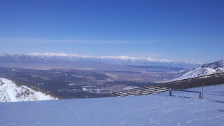
Taken from the top of Chair 3 at Mammoth Mountain.  What a view!

I currently have two different boards I use, and the lesson I learned was about the differences between the two different styles of bindings each board has.

One board came with the bindings as part of a "package deal".  The other, I chose based on the recommendations at the store where I bought them.

By first board has traditional, "two strap" bindings.  Two straps cross your foot, and are ratcheted tight with two small levers.  This is probably the most common binding you'll seen a snowboarder using.

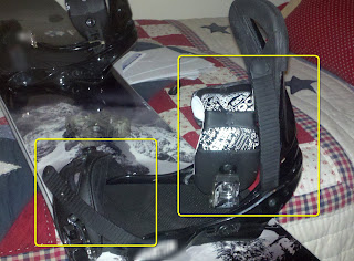
My "two strap" bindings.  The loose straps are circled in yellow


I like them because their easy to adjust.  If they're too loose, just reach down and crank the lever.   If their too tight, release the lever.

Of course there's a downside.  You may not have the exact same setting every time you get off the lift, based on how tight you lock them.  On top of that, they take a little time to get locked down.  So my skier friends are often waiting for me impatiently.   

The straps, circled in yellow, securing my boot.

My second board, has "rear entry" bindings.  In this type of binding, the high back (rear portion of the binding) drops down and you literally "step into" the binding.  The binding is secured by securing a lever that locks the binding to the back of your foot.

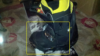
The rear entry binding in the "open" position.  Notice how the stiff back lays down so you can step into it.  The locking lever is circled in yellow

My skier friends (as well as myself), like this binding because it's quick.  I can get of the lift, step into the binding, throw the lock closed, and I'm ready to go.  No fussing with straps like in the traditional, two strap binding. 

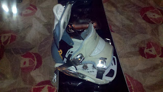
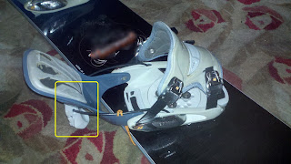
The rear entry binding in the locked position.
With that being said, would this be the better binding? 

Some would say.  But this binding isn't easy to adjust on the fly like my "two strap" style binding.  Because of the design of the "rear entry" style, adjusting the binding means taking off the board, tweaking the binding, and trying it again.

So why have I even taken the time to write this?  You may not like snowboarding.  Maybe the closest you come to the snow are the ice cubes in your favorite drink.

I'm not catering to tell snowboarders to go buy one type of binding over the other.   I'm not even going to tell you which ones I prefer.  That's not the point of this post. 

The point is how I relearned a lesson that experience has taught me before.

You don't get something for nothing.

My "easy to adjust" two strap bindings means more time getting ready after getting off the lift.  My "faster off the lift" rear entry bindings mean I have to take extra time setting everything up, which I'm still working on after purchasing new boots.

In other words, each design had to give up something to gain advantages somewhere else.

In this case, it was ease of adjustment versus speed.  But that's not the only things that could be facing off when designing a product there are a few examples of design "ying and yang".

It could be:
  • Gaining a technological edge but making a product more difficult to maintain
  • Increasing a product's longevity by using materials that are more expensive
  • Increasing product's capabilities but making it more difficult to use

That's the idea.  Of course this list goes on and on.

But the point is, design isn't always about making something better in every aspect.  Many times, something has to be sacrificed for a gain to be made elsewhere.

Is this bad?  Not necessarily.  It's just a fact of life.  As designers, we have to try to maximize the gains while minimizing the losses required to make those gains.  

As consumers, we need to recognize what capabilities are important, and which are not.

It's not always an easy answer, even as we face it every day.  For me it's which set of snowboard bindings.  But for others it could be a computer operating system, an economical car versus an SUV, the list goes on and on.

It's for each of us to decide, both when we design, and when we employ the design created by another.

I know for me, I'll think a little more carefully about which set of snowboard bindings I use!

Monday, February 20, 2012

Material Libraries and Error 1606. Not Friends at All

“From error to error, one discovers the entire truth.”
 Sigmund Freud

Once again, I've crept off to Mammoth Mountain to enjoy the long holiday weekend in the United States.  But true to my geeky nature.  I've still created a blog, albeit a short one. 

Looking at Crawley Lake from Chair 3.  Amazing view!
Last week I encountered an error I hadn't seen before.  An end-user was trying to install Autodesk Product Design Suite 2012 on their machine, but they were encountering the error below when trying to install Autodesk 3ds Max.

So what does this mean? 

The user, understandably frustrated, had also tried to install the Autodesk Showcase, and received the same error.

1606

So we tried running the installation again. It turned out that it wasn't 3ds Max that was having the problem.  It was the material libraries that were associated to 3ds Max were erroring out. 

That explains why Showcase would have the same problem.  It uses the same libraries.

So I resorted to any techies next weapon of choice.   I used Google.  That's right.  That Google. It's a great tool when casting a wide net.

What did I find?  There's a solution for this on the Autodesk website.  It looks like the material libraries had been installed before, than only partially uninstalled.

A quick trip to Add/Remove Programs, and we're up and running again!

So if you run into this error, double check those libraries.

It's a good trip to keep in your pocket as we maintain, and upgrade our Product Design Suite Products.

Wednesday, February 15, 2012

Pacific Design & Manufacturing Show 2012 & Something New!

Mobile blog #2:  Let's see how it goes!  :-)

Today was my day at the Pacific Design & Manufacturing Show in Anaheim.

It was a busy show, with lots going on with CAD software (like at the Autodesk booth) as well as with the 3D Prototyping booths around us.

My laptop ready to go.  Yep, I managed to sneak a warbird picture in there!


There was no shortage of 3D rapid prototyping available!   I love this stuff!

There was a lot of activity today.  I spent a lot if time talking about Autodesk Showcase, Autodesk 3ds Max, and of course Autodesk Inventor.  The whole time the Autodesk team was running presentations.

There was a lot of interest.  Most of all, it seemed like the black cloud of the Great Recession that had been hanging over us the last few years was but a memory.

Good news indeed! 

The team getting ready


And Mr. Mike Aubry goes on stage!
And in the middle of it all.... My Droid X chirps as an e-mail arrives in my inbox.

I open it up, quietly hoping its not disposed foreign royalty offering me untold millions to help them get their fortune out of "SouthNorthern Whatsitsplace". It's not. It's an announcement...

"Autodesk Design Review for the Android is now available". 

There's some other words in there. But it's those few that grab my attention.

With cat like reflexes I go to the Android market and begin downloading. After a few minutes of waiting, there's a glow & the sound of angels singing as the app installs.

There it is! In all its dwf-y glory!  Now you can view 2D and 3D files, as well as markup dwfs on the comfort of your Android based mobile device!

Oh.. .this is cool! 

Yep, pretty cool!

So if you've got an Android and you've been waiting for your own version of Design Review, wait no longer! 

Head over to the Android Market and get your copy!  It's free! 

A good show and a new app!  It's been a great day! 

Turn out the lights
The party's over!

Sunday, February 12, 2012

The Sum of its Parts - Adding Column Values in Autodesk Inventor

“Life is a series of collisions with the future; it is not the sum of what we have been, but what we yearn to be.”
Jose Ortega y Gasset

One of the questions that came up not that long ago was; "How do I add up the mass values for a component in a part list?  I want to show the total mass for several components,  instead of the mass for just one."

How to I get here?  Where the total mass of multiple components is shown.

It's not very difficult, but you do have to know where to look.  I still remember thinking, "That's it?!?" when I first saw. it.

But like so many things, you just have to know where to look.  So guess what I did?

If you're reading this, you probably can guess the answer. 

I created a video, and blogged about it.

So take a look at the video.  As always, I hope it's helpful.

And this tip doesn't just apply to Mass.  It applies to any field that might need summing up!

And before you take a look at the video, there's one more tip.  If you want to make this setting (or any parts list setting), part of your default, remember that you can add them to your Styles Library.

Perhaps I'll create a video for that as well, but that's for a later week.

Enjoy!


Saturday, February 11, 2012

Just for fun. The Random Warbird of the Weekend

I like warbirds... A lot.
Jonathan Landeros


If you've followed my Twitter account, you know I like posting random pictures of one of the warbirds at Planes of Fame, where I volunteer on my weekends.

Now that I'm trying the mobile application on my mobile device, I've decided to share them here.

I know it's not related to CAD in any way, but these airplanes are still marvels of engineering.

Not to mention the stories of those that flew and maintained them.

So here it is.  Something done for the passion of doing it.

The first picture is the P-26 Peashooter, with the N9MB Flying Wing in the background.  Both the only examples of their type still flying.

The next.  A Lockheed P-38 Lightening sitting in the hangar undergoing maintenance to keep her in flying form.

I hope you enjoy them!


The P-26 Peashooter & N9MB Flying Wing


The Lockheed P-38 Lightening.


Sunday, February 05, 2012

Using View Representations to Control Sketch Visibility in Autodesk Inventor

“We write frankly and freely but then we modify before we print”
Mark Twain

Last week, an interesting question was posed to me.  I want to show text on a part, but not on the assembly.  Can that be done inside Autodesk Inventor?

My first thought.....   O_o

My next thought?  How do we do that?

How to we turn off this sketch in the assembly, but keep it in the Part?


Then, I had an idea.  VIEW REPRESENTATIONS!

Will this work!  It sure will!

It works on camera views, component color, and visibility.....  visibility!  Why not sketch visibility! 

It's crazy..... Just crazy enough to work!

So I tried it.... And behold!  It works!

So here it is, a neat little trick that I hadn't even thought of trying!  Enjoy!

P.S.  If you'd like more information on Inventor's View Representations, check out my earlier blog posts.  It's in two parts.  So here is Part 1, and here is Part 2.

And at last, here's the video!