Find us on Google+ Inventor Tales

Thursday, November 15, 2012

And Yet Again, All for Fun - The 8 Sided Die

"DIE, n. The singular of "dice." We seldom hear the word, because there is a prohibitory proverb, "Never say die.""
Ambrose Bierce

This seems to have become a Friday series.  The last few weeks I've placed a model of a gaming die on my blog, and talked about the process I went through making each one.

It stared out as a project for a website (they're the banner on the Dicehouse Games website).

Then I stated being asked if I would supply the models.  So I started making them available for download and describing the steps I used here.

So far, I've created posts for the 20 sided die, the 10 sided die, and the 12 sided die.  Now, I add the 8 sided die. 


The completed die

Here's the completed die as an embedded 3D dwf file.  Click and drag to give it a spin!


This one is a pretty simple model to create, at least when compared to the others!

  • First, I sketched a square on an origin workplane.  In my case, I chose the XZ workplane. 

The first step that starts it all


Next, I bisected the square with a line, on a plane perpendicular to the sketch I first used.  It's worth noting that I later on realized that I only needed half the line, but I left the die as I started it.

Added the perpendicular line.  I later realized I didn't need the whole line

Now, it's time to create a loft from the square, to one of the line's endpoints.

Creating half of the die

With half the die completed, I used the Mirror command to create the other half of the die.

Using the Mirror command to create the other half of the die

That takes care of the heavy lifting!  Now, I just add a fillet to break the sharp edges.  Notice that I used the "All Round" option to select all the external edges at once.

Breaking the sharp edge

Finally, the long tedious task of adding the number.  This hasn't changed, its just a matter of creating a sketch with the number, and extruding it a shallow distance.  At least there are fewer now!

The process of adding the numbers


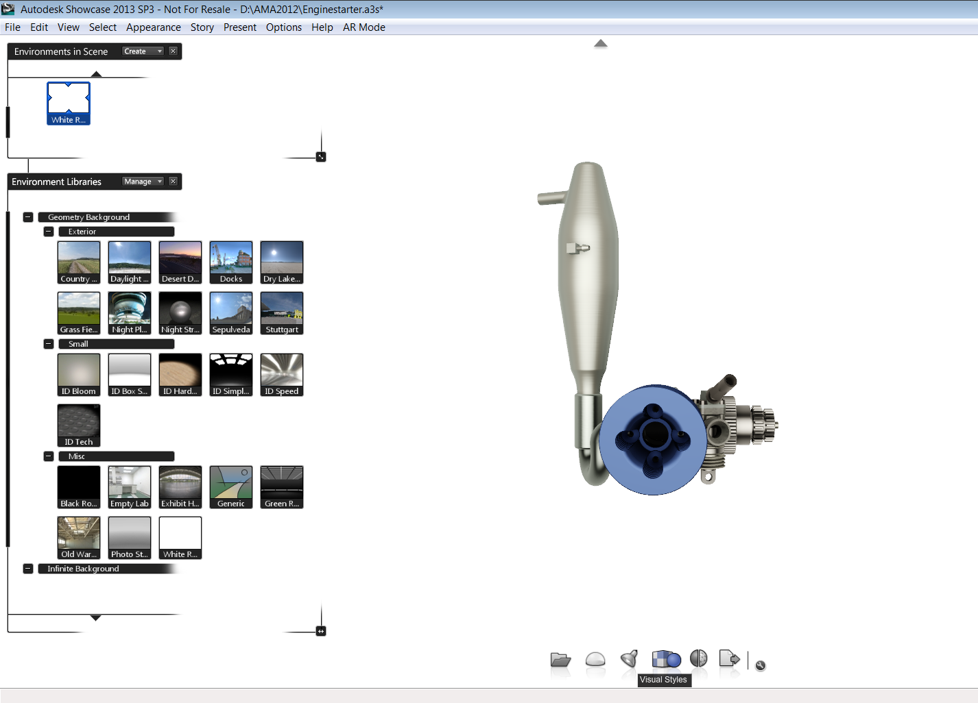
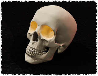
And because I can, here's the quick rendering in Autodesk Showcase.

And a rendering to make it look cool!

P.S. If you're wondering why I didn't loft from the line's endpoint, to the square, to the other endpoint, here's what happened when I tried.


Needless to say, this wouldn't have made a very good die.  So I changed my approach, and used the Mirror command instead.  But now you know why I created the line the way I did.  It's a vestige of an aborted work process!

Doh!  Not what I wanted!

And of course, here are the links to download the files.
Click here for the Autodesk 360 link

Click here for the GrabCAD link

Enjoy!  I hope to see some of you at Autodesk University 2012!


Tuesday, November 13, 2012

A Guest Video - Importing 3dsMax Design Animations into Showcase

Animation can explain whatever the mind of man can conceive. This facility makes it the most versatile and explicit means of communication yet devised for quick mass appreciation.
Walt Disney

Marion Landry of Autodesk has some great videos on things that can be done to get the most out of Autodesk Showcase. 

In this "guest video" from her YouTube channel, she describes how an animation from Autodesk 3dsMax Design can be imported into Autodesk Showcase.

It's a slick trick that combines the best of both worlds. 

Take a look and this video, and some of the other videos on her channel!  I think you'll find a lot of cool tricks you can use! 


Sunday, November 11, 2012

From Concept to "Augmented Reality" in Autodesk Showcase 2013

“Audacity augments courage; hesitation, fear.”
Publilius Syrus

Edit by Jonathan Landeros


As of May 2013, The Augmented Reality Plugin for Autodesk Showcase has been retired.  I liked this plugin, and the post does state that it may be back at a later date. 

My fingers are crossed!


Shame on me for not updating this sooner, but things sometimes go into the archives, and collect dust.

******************


For some time how, the Augmented Reality Plugin for Autodesk Showcase has been available.  If you haven't seen it, check out the video below from Autodesk Labs.

This video from Autodesk Labs describes the setup and configuration perfectly.


But in a Twitter conversation among Scott Moyse, David Gate, and Clint Brown, the following ideas were presented

1) Instead of printing out the markers, try using a mobile device, such as an iPad or Android to host the marker
Holding the iPad with the QR code marker

2) Instead of the markers provided with the plugin, use an image created from the scene.  This will make it look like the 3D model is "growing" from the 2D image.

I didn't have as much luck with this step.  I was able to create a marker using the exported 2D image, but when I tried to use it as a marker, the model seemed to have a difficult time picking up the marker, it was jumpy and inconsistent.

But I did get the effect I wanted.  It took some trial and error, a few more ideas, and a slightly different approach.

And here are those steps!

  • The first step was to create an image of the scene I wanted to use, and set up the angle I wanted using the "White Room" environment.  I also turned off the shadows for this environment. 

Using the "White Room" environment.
  • I also went to the Appearance>Directional Light and Shadows
Locating the pulldown

  • I then set the "Shadow Casting for All Objects" to "Specified Objects, and changed it's setting to "Make no Objects Cast Shadows". 
Turning off Shadows

  • Next, I published the image to a *.jpg

Publishing the image

  • I then created a decal, using the jpg I just exported. 

Creating the decal, with the critical settings shown

  • I then placed that decal on a "floor" I had created in Inventor, then imported and positioned in Showcase. 

The decal placed, and being positioned
 Once this is done, I setup the Augmented Reality and I was ready to go!   And here's the video that goes with it!


P.S.  If you're going to Autodesk University in Las Vegas this year, look for me!  I'm going to be there myself!

And feel free to leave a comment below!


Friday, November 09, 2012

All for Fun Again - Modeling the 12 Sided Die

"Death and dice level all distinction."
Samuel Foote 

Today is Friday, and you might have noticed that in the last couple of weeks I've been challenging myself by created 3D models of gaming dice.

So far, I've created to 20 sided die, the 10 sided die, and now I've added the 12 sided die.

P.S. the view below is an embedded 3D DWF that can be panned, zoomed, & rotated!


This one ended up being the most challenging so far, at least until I got the construction method down.  Once I had that figured out, it wasn't hard, just time consuming.


So here are the steps I used to build it!

The first thing I did was locate directions on how to build the shape that eventually becomes the die.  It's called a dodecahedron, and like the 20 sided die, I found it's construction on Wikipedia.  It was composed of using a rectangle, and points placed at certain coordinates in space.  The Wikipedia article gave me these coordinates.

The construction for the die
  • I took this information, and using a rectangle extruded as a surface, and three rectangles, created the required points.  The points are the verticies of each figure. 

The skeleton that starts it all


  • Next, comes the process of creating the faces.  I used a workplane between three point on the skeleton.  Created a 2D sketch, and started projecting geometry and sketching the boundaries of the face.  This takes some time and patience.


Getting started with the construction

Further along in the construction.  I turned off the workplane visibility to try to make the image a little more clear.

  • Once the skeleton was finished, I went through and created boundary patches that filled in each face of the die.

Now surfaces close up the shape
  • With the surfaces created, now I used the "Stitch" command to seal surfaces up, converting them to a solid.

The converted solid
  • My next step was to add a fillet to break all the edges.

The fillet added to the die.

  •  Finally, the long, long process of adding 12 sets of numbers to the die.  It's not difficult, but like most things creating these dies, it takes time, it's an exercise in more time, and more patience.

The sketches in the process of getting created.

  • Finish the text and I'm done
  • Finally, a drop into Showcase to give it a little flair!


So there it is, one more die out of the way.  I still plan on doing the rest, 8 sided, 4 sided, and 6 sided (which is easy). 

On a final note, if you want to download the models.  You find them on GrabCAD and Autodesk 360.

Click here for Autodesk 360 Download

Click here for GrabCAD Download

Tuesday, November 06, 2012

A life extension for the Augmented Reality Plugin for Autodesk Showcase

“It is our imagination that transforms itself into reality, through our physical strength and endeavours.”
Helen Araromi

Edit by Jonathan Landeros

As of May 2013, The Augmented Reality Plugin for Autodesk Showcase has been retired.  I liked this plugin, and the post does state that it may be back at a later date. 

My fingers are crossed!


Shame on me for not updating this sooner, but things sometimes go into the archives, and collect dust.

******************
Tonight is a quick blog on a cool bit of news.

A few months ago, the Augmented Reality Plugin for Autodesk Showcase was released on Autodesk Labs.

This cool plugin for Showcase 2013 allowed a webcam to take an image, and project it into the Showcase scene.

 It was so cool, I bought a webcam just to be able to try it out!   And once I tried it, it was indeed very cool!

An example from my own Augmented Reality Session.  Pretty cool!  But I need to adjust the marker!

 But it had one big downside.  It would timeout on October 31st, 2012.  So it's tenure on Labs was seemingly going to be short.

But just today, I was asked about it again by a user.  I checked out the website, and BEHOLD!  The Augmented Reality plugin has gotten a life extension until January 31st, 2013.

So if you have a webcam and Autodesk Showcase 2013, download it and give it a try.  I don't think you'll be disappointed!  

Here's a video created by the Autodesk Labs Team.  Take a look and give it a download!  I think you're going to like what you see!

Download the Augmented Reality Plugin For Autodesk Showcase here! 


Sunday, November 04, 2012

Renaming Files in Autodesk Inventor's Design Assistant


What's in a name? That which we call a rose,
By any other name would smell as sweet;
William Shakespeare ~ Romeo & Juliet

I've made this mistake more times that I would like to admit.  I've been working in an assembly in Autodesk Inventor, and when I create a component, I forget to rename it and I end up accepting the default of "Part1.ipt".

Naturally, I don't realize that I've forgotten this step, and I end up creating an entirely new, default, name I never intended.

To make matters worse, I usually don't realize this until I've created a detailed part.  As a matter of face, I usually realize my mistake when I'm actually saving my final version.

Essentially, what I've just described is a situation where I've created a new component, fouled up the name, and gotten to a point where undoing it and starting over isn't my best option.

The assembly with the part I named wrong


So how did I manage to get out of it?

My first option was to check the files into Autodesk Vault, and rename them there.  That option works just fine, and I've used that in the past.

But what I really wanted to do, was rename the files before I put them in Vault.  I just didn't want to check the assembly in just to rename them in Vault.

Before I continue, I have make sure to note that the file I'm renaming is NOT yet in Vault.  If it was in Vault, then I'd use the Vault Rename tool.   But I digress....

To rename the offending file, I used a tool called Design Assistant, which is included in Inventor, and doesn't require Vault.  As a matter of fact, it doesn't need Vault at all.

What is Design Assistant?  How does it work?

Design Assistant is a tool, included with every installation of Autodesk Inventor that is intended to help with file management.  It has several tasks, but one of which, is to rename files   So where is it located, and how did I get to it?

  • My first step to locate Design Assistant was to go to Windows Start>Autodesk>Autodesk Inventor 2013 and locat Design Assistant. 

Accessing Design Assistant

  •  Starting it up, I need to choose the assembly containing the part I've messed up. Once the assembly is open, I chose the "Manage" option.  Now I can see the components that make up the assembly.

Locating the offending part in Design Assistant

  • In my next step, I find the component I need to rename.  I right click on the the "Action" cell, and choose "Rename".

Right click and choose "Rename".

  • Now the component's row highlights.  Next I choose the component's name and select "Change Name"

Choose "Change Name".  Notice the Action cell has changed too!

  • A dialog box opens and I can now rename the file.

Renaming the fie


  • With the file renamed, I save the changes, and I'm ready to go.  

All that's left is to click "Save"

And I'm done!

  •  I can now check the files into Vault, and the correct name goes into Vault, without requiring that I go in and change it.

Checking into Vault, and I'm done!


So that's how a file can be renamed using Autodesk Inventor's Design Assistant.  But before I give you the video, there are a couple of things to note!

 Yes, I know I'm repeating myself.  But I think it's worth repeating!

  • Design Assistant doesn't require Vault.  So if you're a user who isn't using Vault, this can help out a great deal. 
  • However if you are using Vault, don't use this to replace Vault's Rename tool. As a matter of fact, if the file is already vaulted, make sure to use the Vault Rename tool!  Design Assistant should only be used for files that aren't in Vault yet!  Failure to heed this warning could lead to file resolution issues, and being excessively mocked by your peers! 
On that note, here is the video!  I hope you find it useful, and make sure to use it wisely!

And if there's any experience you'd like to add, throw a comment in below! 


***************************Edited October 10, 2013**********************************

A comment below mentioned that they had lost links to drawings when using the process.  Most of my work with Design Assistant didn't involve drawings.  I rarely, if ever have drawings created when I'm using Design assistant this way.

However, I did find a link on the Autodesk Discussion Group here, that addresses this. 

Sorry if I caused any confusion, I hope this makes this tip a little more complete.

Friday, November 02, 2012

For a Little More Fun! - Modeling a 10 sided die!

“The dice of Zeus always fall luckily.”
Sophocles

After creating the 20 sided die in my post last week, I decided to embrace my inner geek even further and create another die of the standard gamers set.

This time I chose to create a model of the 10 sided die.

The finished 10 sided die
To add a little more fun, here's a new trick I'm trying.  Embedding a dwf of the die inside the webpage!  Try giving it a rotate and pan!


When I started to look at building this die, I found this model easier to create that the 20 sided die.  But even though I thought it was a little easier to create, I also found it had it's own set of challenges.  It took me a few tries before I got a result I was happy with.

I ended up using two lofts, and trimming the plane where they met to get the result.  I then added fillets to clean up the edges and get the result I was looking for. 

But, without further adieu, here are the steps! 

  • The first step was to create a single line on a sketch plane.  I'm going to use each end of the line as one end of two lofts I'm going to create. I also made sure that the midpoint of the line was placed at the origin.  This will let me use the origin workplanes to create sketches in my next steps.

The first line defining the top and bottom of the die.

  • Next I created a sketch on my origin plane, added a pentagon, and dimensioned it.

The additional sketch added.
  • Now I'm ready to loft between the two.  I choose the loft tool, and loft between the pentagon and one of the line's endpoints. 

Creating the loft

The finished loft

  • Before I started modeling, I looked at an image of a real die, I realized that the upper and lower halves were offset, so I couldn't use the same loft.  So I created a second pentagon, rotated from the first, and repeated the steps above.

Creating the second loft.  Notice how it's offset from the first.
  • Now I was left with sharp overhangs on the die that weren't going to work at all. It was time to clean those up!


The die before cleaning up.  Not pretty at all!
  • To clean up the sharp corners, I created a sketch where the two pentagons meet.  (Note I used slice graphics, just like in my previous post here).  I sketched a circle, then used Extrude with the intersect option remove the sharp corners.
Creating the feature for the Extrude commad


Extruding using the intersect option
  • Now the hard work is done.  All that is left is the tedious work of adding the numbers.

Adding the numbers to the die
  • And finally, using the fillet tool to round off the sharp corners!
All done!

 A quick rendering, in Autodesk Showcase, and I'm ready to go!


 Just like with the 20 sided die, below are two links where you can download the model if you'd like.  And just like before, all I ask is that you give a me a little nod if you decide to use the model.  Enjoy!

Download from Autodesk 360 

Download from GrabCAD (login required)

Wednesday, October 31, 2012

Happy Halloween! & Flipping Normals in Autodesk Showcase!

“For me, writing something in the spirit of Halloween is like Mother Teresa writing on charity and sacrifice. It's just second nature to me.”
Danny Elfman

Today's blog is just a quick blog to say "Happy Halloween", and add a quick tip for Autodesk Showcase.  . 

Earlier today I downloaded a 3D model of a skull, in a STL format, from GrabCAD and imported it into Showcase.

But once the file imported.  It looked dark.  Almost like charcoal.   It was like the environment light was having no effect on it.


This skull shouldn't look this dark.  Somethings wrong (hint: check normals)

Experience has taught me what the cause of this is.  But not everyone may know the secret. 

The normals on the skull were all reversed. 

For those who may not  be as familiar with surface normals, each surface in Showcase has a positive and negative side, often referred positive and negative normals. 

While I can't say I know all technological reasons for the how the normals behave.  I do know one thing.  If the normals are backwards, which sometimes happens on imported models, the object won't light correctly.  That's what's going on with the skull.

So now that I know what's wrong, how do I fix it?

  • First, I went to the "Appearance" pull down menu and choose "Visual Styles Library". 

Bringing up the Visual Styles Library


  • Once the Visual Styles Library menu appears, expand the "Diagnostics" section.  This is where I find the option for "Normals".  Choosing this option, I see that the entire skull shades yellow.

Viewing the Normals
  • The yellow indicates that I'm looking at the negative side of the normal. This is why the skull isn't lighting correctly.  Showcase is also helping me out by telling me to Select an object and hit the "F8" key to flip the normals.

The yellow tells me I'm looking at the negative (back) side of the normal
  • I can hit the F8 key or I can select my objects and choose Edit>Reverse Normals from the pulldown menus.

Flipping the normals
  • The normals will flip, and the skull will turn blue.  This tells me I'm looking at the positive side of the normals now. 

The normals are flipped!

  • Now, all I have to do is select a new option from the visual styles (I chose the "Both Shadows and Ambient Shadows" option)


  • Now the skull looks a whole lot better, and I'm ready to complete the rendering.  Add a few shadows and lights, and I have something I can say "Happy Halloween with!

The skull with some materials and lighting

And with glowing eyes!
So that's it, a quick tip on flipping the normals on a model!  Have a great holiday everyone!