Find us on Google+ Inventor Tales

Sunday, April 28, 2013

Using the New "Depth of Field" Setting in Autodesk Showcase 2014

“There is only you and your camera. The limitations in your photography are in yourself, for what we see is what we are.”
Ernst Haas

One of the challenges in using Autodesk Showcase is getting the rendering, and particular, the focus of the rendering stand out.

Its one of the reasons that many times, I don't like putting the subject of a rendering "in it's natural environment".  It looks like it belongs there, and it just disappears.

But on the other hands, there are definitely times that there's a benefit to putting a subject where it belongs, in a shop, in a lab, or on a street, for example, instead of in an "empty photo room".

One of the new tools added to Autodesk Showcase 2014 is the "Depth of Field" setting, which, like the F-Stop on a camera, controls how the scene is focus, and how objects "blur away" as they get further from the "lens" in the scene.

In the scene I'm using here, I've taken a picture of the Planes of Fame B-25 Mitchell, created a backdrop, and inserted two engines, which are models I downloaded from GrabCAD at the link here. 

I'm not using any depth of field settings.  I'm just using the backdrop "as is".

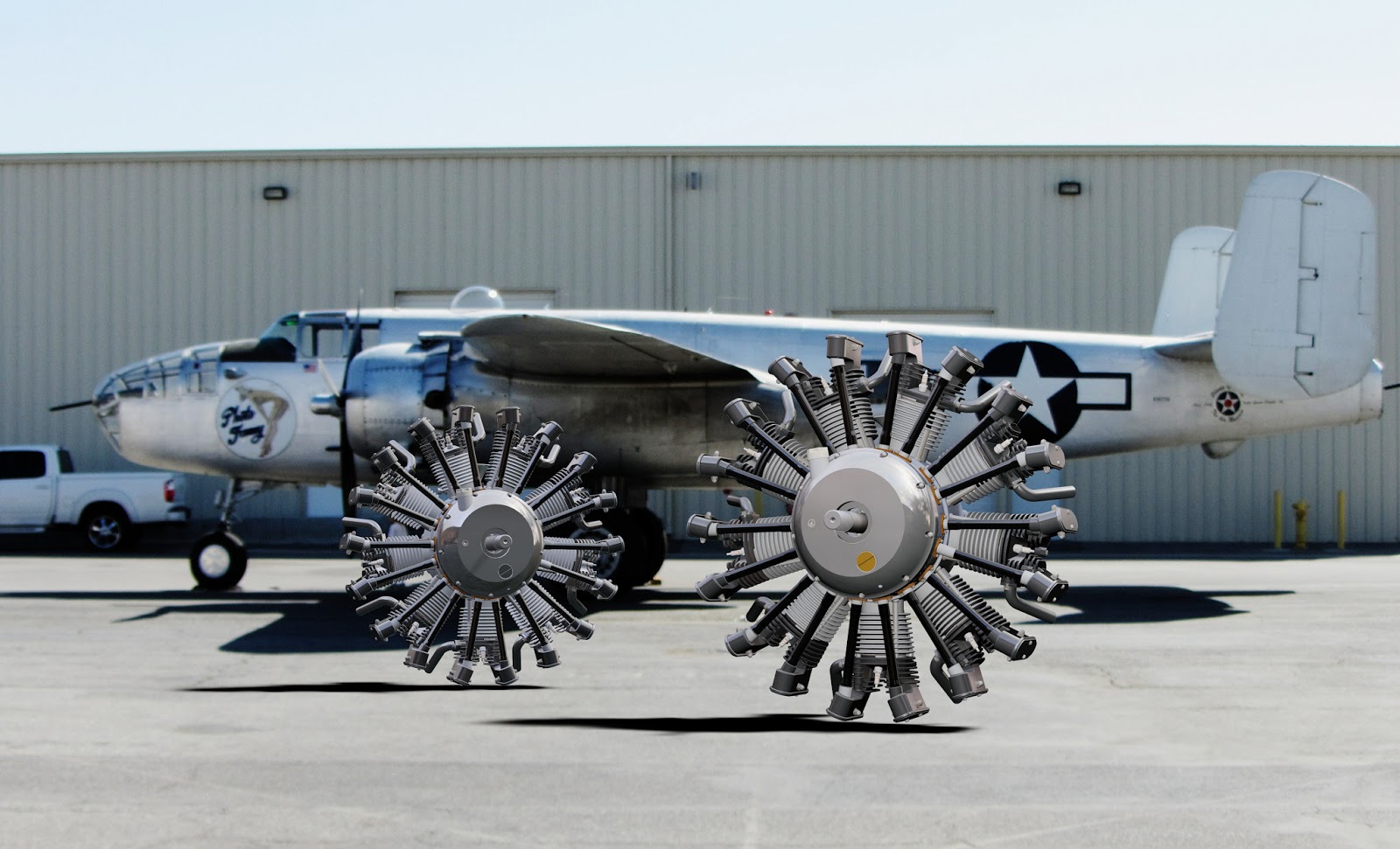
The two engines place in the scene with the B-25

Everything is in focus.  And while it might be easy to look at the engines in the foreground, it's also possible that the person viewing the image might not be immediately drawn to the engines

With the Depth of Field setting, the background can be blurred and the focus of the scene can quickly be places on the engine.  So how does depth of field work?

I start by going to View>Camera Properties.

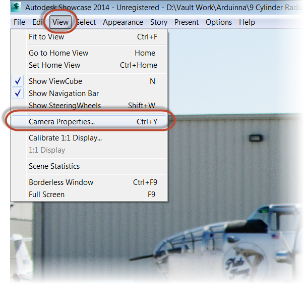
Choosing Camera properties.

Once the Camera Properties come up, click "Show More Controls" under lens effects.  "Depth of Field" will appear there, check the box to enable it.

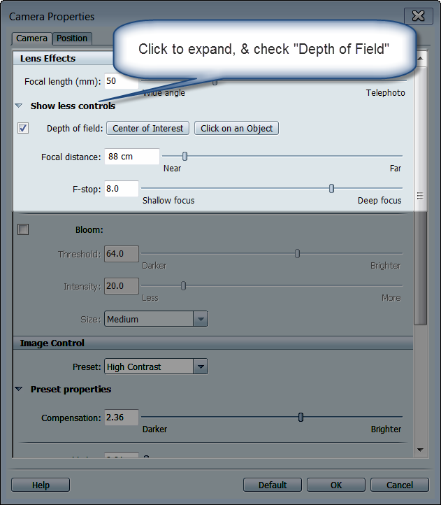
Choosing depth of field.

Now, I can select "Click on Object", and choose the engine closest to the foreground on my screen.  This tells  Showcase where I'm "aiming the camera".

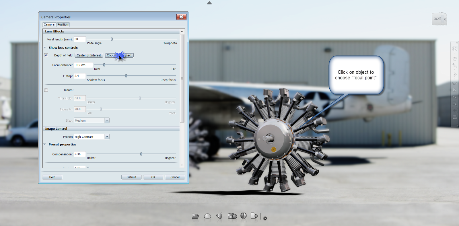
Choosing the object of focus
Once this is done the sliders for Focal Distance and F-Stop can be used to change the focus of the scene, and bring one object into focus, and blurring the others to bring out the desired effect.


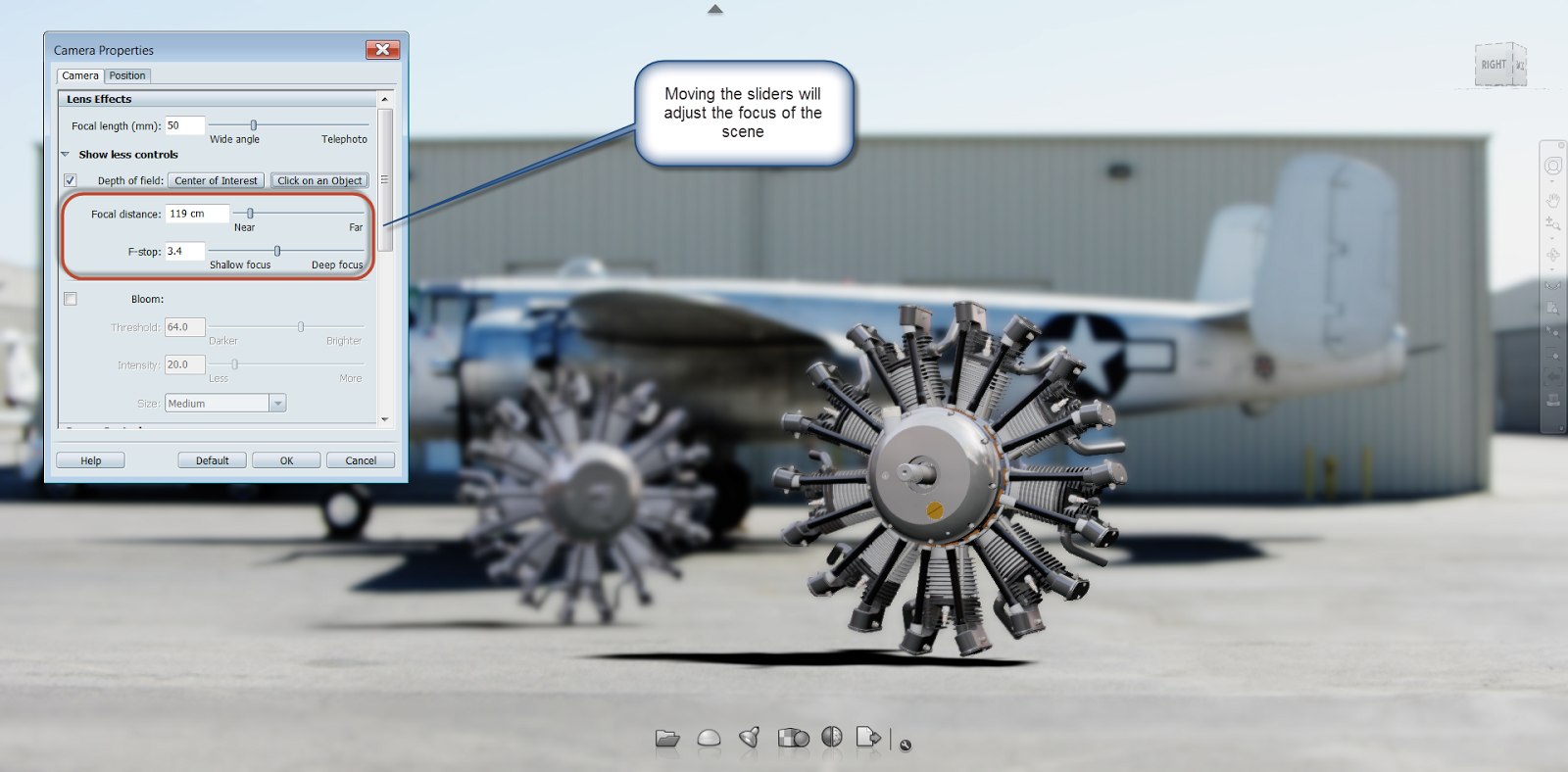
Changing the Depth of Field settings

Once the desired effect is achieved, select OK to accept the new result!

The completed result

So go ahead and give these settings a try.  Like so many settings in Showcase, there's not a right or wrong way, just what you like!

And for the steps in a video form, look below!


Tuesday, April 23, 2013

Migrating Styles to Autodesk Inventor 2014 from a Previous Release

“The flow of migration is not this inexorable, constant increase.”
Roberto Suro

It's that time of year again.  Autodesk Inventor 2014 is hitting the streets, and I'm kicking the tires on the new release. 

One of the first steps I like to do, is migrate my custom styles (dimension styles, Sheet Metal Rules, Thread Data, etc) and templates to the current release

In this post, I'm only going to focus on migrating my styles.

Getting started with the styles.

The Wikihelp for Autodesk 2014 contains the steps for migration, but states that I can:

"Continue to use the migrated library. It will function exactly as it did in the previous release. However, you will not be able to take advantage of the corrections and additional styles that Autodesk has added in the latest release."

Translation?  If I just migrate all my 2013 styles libraries to 2014, I may be missing some good stuff. In light of that, I decided to merge my custom libraries with the standard 2014 styles, which is a departure from the method I used in my post a couple of years ago.

So here's how I went about it this year.

First I made a decision where I'm going to keep my 2014 design data.  Since I'm on a laptop, I keep them in a "Utility Folder", based on version.  

True, the default locations could be used, but I like having my styles in a location I choose.

The Utility Folders I like, based on Inventor Version

Now, I direct my installation of Inventor 2014 to look at that folder.  This can be done in one of two places, in Application Options with the File Tab.


Or in the Folder Options section of the project.  Note, that if the paths specified in Folder Options is different than that in Applications Options, the Folder Options path will be used.


The location as used in the project
I'm going to copy my default styles libraries from Inventor 2014s default location (which is the one depicted in Application Options), to the "Utility Folder" I created.

Copying the standard styles from the default location to my custom location.


With that out of the way, I  copy the Styles from my previous release, Inventor 2013, into a new "Transition" directory.  The reason for this is twofold.

1) I'm not playing with my live 2013 styles
2) I can still use that old data to work with the previous version of Inventor, which I often need to do.

Copy and Paste my previous versions styles to the transition folder

With my "setup" completed, I'm going to go ahead and open the Styles Library Manager, Located in Windows Start>Programs>Autodesk>Inventor 2014>Tools

Locating the Styles Library Manager
 Once the Styles Library Manager is open, I'll browse to my "Transition Folder" from the left pane, and my new location in the right pane.  The custom styles, which are currently missing from the 2014 library, are shown in blue.  These are my custom libraries

A sample of my Dimension Styles.  Two of my custom styles are in blue

Clicking on the "Migrate" button, the libraries will be migrated for use with 2014.

Migrations done!

After migration, the arrows to copy the style to the new location for Inventor 2014 light up, and by clicking the button, the styles are transferred over.


Click to transfer over
It's just a matter for repeating this for any other styles that need to be done, and soon, you'll be off and running!

An example of the transferred libraries
And for more information, naturally, I've included a video below!

Sunday, April 21, 2013

Enhance Your Presentations in Autodesk Inventor - A Guest Video

“One should strive to improve one's capabilities. One should enhance his abilities only in the positive direction. ”
Rig Veda


This weekend was a busy weekend as I tried to get some personal errands wrapped up, as well as spending my usual Saturday at Planes of Fame working on fabric control surfaces, and watching the first arrivals for the big airshow on May 4th and 5th.

An aileron for the D4Y Suisei (allied code name "Judy") in the process of restoration

Warbirds gathering for the airshow.  From front to back a T-6/SNJ Texan, a Douglass AD Skyradier, a Vought F4U Corsair, a Northrop N9MB Flying Wing, a Douglass SBD Dauntless, and way back, a Douglass C-47 can be seen.

Nonetheless, I ran out a time to put together a quality blog post, so I'll be creating one a little later this week.  But in the mean time, check out the Tech Tip created by Bill Bogan, fellow compatriot at KETIV Technologies.  He shows us some tricks that can be created with presentation files!


Wednesday, April 17, 2013

Changing Default Edge Display Settings in Autodesk Inventor

“When one jumps over the edge, one is bound to land somewhere.”
D.H. Lawrence

Edge display in an Autodesk Inventor model is a setting I find helpful to change at times.  Most of the time, I prefer to work with the Edge Display turned off, but there are times that I find it helpful to turn  it on in order to make the edges of components a little more visible.

The image below shows the first setting, with Edge Display turned off.  This is my usual personal preference. 

Edge Display off

Next , the edge display is turned on, which I like to use in certain cases.

Edge Display on

But not everyone likes my preferences, that's whey they're my "personal preferences".   So how can the settings be changed to change which setting Inventor initially uses?

If the default settings in Edge Display are located in Tools>Application Options, on the Display Tab


Finding the settings
The first thing to notice is that there is a radio button for "Use Application Options" or "Use Document Settings".  These buttons decide whether the setting will be applied via Application Options, which will set the edge display to affect all models that are opened (Use Application Options), or if the setting is set from with in the document itself (Use Document Settings).


Personally, I prefer Use Application Options, but that's just my choice.   Clicking settings will open up the Display Appearance Dialog box. 

Opening the Display Appearance Dialog box
Now, it's just a matter of choosing which setting you prefer.  In the example below, I've selected "Shaded with Edges".

Changing the style.
 It's important to note that the setting won't affect the files that are currently open.   Don't panic!  The next time the files are opened, the settings will take effect.

That's it! All set!
Happy Inventing!

Sunday, April 14, 2013

Linking Parameters from One Part to Another in Autodesk Inventor

“New links must be forged as old ones rust”
Jane Howard

Last week, I was asked "Can you link parameters from one part to another in Inventor?" 

I had to think back a bit.  It's been several years since I had used this method, but in short, yes it can be done, and this is how to do it.

First, I have two parts, a shaft, and a base that contains a bore shown in an assembly file.  The shaft has a dimension that may vary, but I know the corresponding bore has to be .025 larger than the shaft.  I'm purposefully keeping the clearance large so the change is easier to see.

 Looking at the image below, it's easy to tell that the clearance is far larger than .025.  I'll use parameters to like the diameter of the bore to the diameter of the shaft.


The shaft and bore.  The dimensions are unlinked.

The first step to perform is to edit the shaft part, and rename the parameters that define the shaft diameter.  This step isn't really necessary, but it does make the parameters easier to work with.  I'm also going to check the "Export Parameter" check box.

Parameters are located on the "Manage" tab. 

Preparing the Parameter for use.
With the shaft parameters prepared, finish editing the shaft, and start editing the base.   Edit the parameters for this component as well.  Note that the parameter for the hole diameter has already been given a unique name.

Showing the parameters for the bore.
The first step to linking the two files together is to click on the "Link" button.

The "Link" button is in the lower left of the parameters box.
This will cause the Open dialog box to appear.  Change the file type from Excel files, to Inventor files.  I'll select the Shaft.ipt part, and click "Open".

Opening the file to link.

The Link Parameters dialog appears, this is where the parameters to be linked can be selected.  Although multiple parameters can be selected, in this case, only the parameter Shaft_Dia needs to be selected.  Click on the icon so a yellow "+" symbol appears.


Selecting the parameters to link

Clicking "OK", the parameter will be linked into the file containing the bore.  The parameter will appear in gray, at the bottom of the parameters dialog box.


The parameters are added.

Now, an equation can be built using this parameter, adding the clearance of .025 inches.  The image below shows the equation created in the parameters dialog box.

The equation created.

 Closing the dialog box will reveal that the bore as already sized according to the new equation that's been added.  In the image below, the assembly has been sectioned, and the shaft made flush with the bore to make the gap more visible.

The gap added.
The real strength of this method, is when the shaft is re-sized.  Since the shaft and bore diameters are linked, the dimension of the shaft will change the diameter of the bore, while maintaining the clearance!

First changing the size of the shaft.

Changing the parameter. The shaft has already updated.
Finishing the component edit will reveal that the bore has updated while maintaining the clearance.

The bore re-sized.

This application can be very helpful in dynamic designs where component dimensions are going to change often, and a little bit of "light automation" can be helpful. 

Where is that case to be found?  That's up to you! 

For a video showing the steps used above, look below! In my video, I used .015 inches for the clearance.  But the ideas are still the same!


Sunday, April 07, 2013

Using Autodesk 360 to Create an Interactive View on a Webpage

“A pessimist only sees the dark side of the clouds, and mopes; a philosopher sees both sides and shrugs; an optimist doesn't see the clouds at all--he's walking on them.”
Leonard L. Levinson

Sometimes, the most interesting and unique things happen completely by accident.  And I'm going to discuss an instance of that here.

Over the last few months, I've been delving deeper into the use of my Autodesk 360 site, and exploring it's capabilities a little more deeply.

And there's a lot that can be done.  It can store files, it can control who has permissions to view and download files, it can be used to run, analysis, simulation, and rendering projects, as well as product life cycle management.   It can even be used as an online view for someone who needs to see your data.


In this post, I talk about a subtle capability that can add a lot of bang for the buck.  Embedding a viewable dwf file in a website.

A 3D dwf can do a lot to help make a design to life.  The viewer can zoom rotate, pan, and interact with the file.  These capabilities can add a lot of clarity, and value, to a proposal, or to the evolution of a design process.


So how can you create the embedded code into a webpage, like I've done above?

First, create a dwf from the source file.  In my example, I'm using a dwf of the 4 sided die I created a few months ago. 


Once the dwf is exported, switch to your Autodesk 360 account, and prepare to upload the file to the account.  In my example, I've created a folder called "Blog Shares".  But you can name the folder anything you want.  It's not necessary to create a folder, but I prefer to.  It helps organize things


Browsing into this folder, I'll go ahead and select "Upload" to begin the process of selecting and uploading the file.

 This opens up the window to browse to the file to upload.  Files can be dragged and dropped, or folder browsing can be used to add the files.  Multiple files can be added using this method as well.


In this case, I'm only adding one file, so I'll select it, and hit the "Upload Now" button.


The file will upload, and after a few minutes, the dwf file will generate it's view.  However, it's completely locked down, and nobody but the person who created it can see it.


In order to share the file, I'm going to move my cursor over the dwfx file.  I'll see icons for a Preview, Assign Categories, Actions, and Add Comments.

I'll select "Actions", choose "Sharing", and then choose "Public Sharing"


A dialog box will appear where Public Sharing can be turned on.  A link is created where the file can be downloaded, e-mailed, previewed, and finally, embedded.

Choosing "Embed", Autodesk 360 creates html code that can be used to copy and paste into a webpage (like this one!) and create the embedded preview above


So that's how Autodesk 360 can help amp up your website.  If you haven't checked out Autodesk 360 yet, it's worth taking a look at.  You get 3GB of storage just for starting it up!

One thing to note, I did edit the code to make the view fit better on my page.  But that's the only alteration I made.

And for the video version of this, take a look at that embedded file below!

<iframe width="545" height="409" src="http://www.youtube.com/embed/4vculzWL_dI" frameborder="0" allowfullscreen></iframe>


Friday, April 05, 2013

Working for the Weekend & Going to the (Content) Library

“A library is a repository of medicine for the mind”
Greek proverb 

I'm occasionally asked where additional content center libraries can be found for Autodesk Inventor's Frame Generator, and it seems those are not easy things to come by.

I suspect that's because of the time involved in creating them, once someone invest the time to make one, they're reluctant to just give them away.   But do I know for sure?  No. I don't.

But a few weeks ago, I was walking the virtual isles of the file sharing site GrabCAD, and low and behold, what do I find?  Inventor Content Center Libraries for 8020 extrusion!  The files were created and uploaded by Stan Wile, and he deserves a big thanks for sharing the work he's created.

A sample of the extrusions use to create a frame. I've turned off one of the extrusions for clarity

The files are in *idcl (Inventor Desktop Content Library) format, and here's how they can be made available to your installation of Autodesk Inventor 2013.  Once those files are downloaded, it's time to get started.

First go to Tools>Application Options>Content Center Tab, and find the location where the Desktop Content Center is located.


The Content Library locations.

Now go to this location, and paste the *.idcl files into this location.  The other Desktop Content Libraries will be here.


The 8020 library placed into the Desktop Content Center location

But there are a couple of more steps before everything is ready to go.

The libraries have to be made available to the project using the libraries.  To start this step, go to the Application icon (I call this the "Big I"), and choose Manage>Projects

Navigating to the project file location


Once the Projects dialog box appears, click on the "Configure Content Center" icon at the lower right of the dialog box, just above the "Done" button.

Configuring the Content Center Libraries
Another dialog box comes up and the library can be added to this project by checking the box next to the 8020 library.

Adding the library to the project

Now, the 8020 extrusions can be used just like any frame generator component.

Using the new extrusions

If you want to download and add these extrusions to your own installation of Inventor, you can download them from GrabCAD by clicking here.  Yes, there is a membership required, but once you get into GrabCAD, I think you'll like a lot of the things it has to offer.

Also, if you're using a version of Inventor earlier than 2013, all is not lost.  Stan has also provided the 3D models of the profiles, which can be used to create your own Content Library by using the instructions at the Autodesk link here.

A Final Note

The libraries provided are for Inventor's Desktop Content.  If you're using Autodesk Vault, and wish to move the files to the Vault Content Center Libraries.  They can be transferred by using the Library Transfer Guide to be placed into the Vault Content Center Library.

Accessing the Library Transfer Guide