Find us on Google+ Inventor Tales

Monday, April 27, 2015

A Little Side Project Now Shared on GrabCAD - The NutPlate iPart

Every so often I like to create content just for the fun of creating it.

It does keep me practicing my Inventor skills, and sometimes, I just enjoy doing it.

One thing I've been doing over the course of the last few months has been creating some standard aviation style hardware.  I've created them as iParts, similar to I have in similar posts.

In this case, I've created a nut plate based on the part number NASM21047.  I found this data on the Coast Fabrication website, which I've found to be a great resource for these types of components

A sample of the nutplate iPart. 


I've created the parts using the same methods as in my post from a few months ago.  The steps are largely the same, so I won't recreate those steps here.  They're already in that post.

However, there are a couple of differences that are worth pointing out in this new version.

In this model, I've suppressed features in some of my iPart members.  This is because some of variations have a counterbore in the bottom, and others don't.  As a result, you'll see lines where the counterbore features, and the feature attached to them, are suppressed.

Features that need to be Suppressed for some family members can be added on the Suppression tab.

A Suppression Column.  I like to type out the words myself.

Suppression and compression of a feature by typing one of several values in the field.

Suppress a feature by entering one of the following:

  • Suppress
  • suppress
  • S
  • s
  • 0
Compute (turn on) a feature with one of the following.
  • Compute
  • compute
  • C
  • c
  • 1

I've also added a material column this time around, this makes sure the mass is accurate for each variation as well.

You can tell a column to be a Material column by right clicking on the header, and selecting the Material Column option.  Then type in the material you want in the field.

Notice the Material Column

Mostly, I just want to create a sample that you can use to get ideas how to create an iPart, or use this as inspiration to build your own iPart!

After all, why do the work if it's not going to be shared.  The iPart was built in Inventor 2015.

Take a look at the GrabCAD link here!  A login is required, but it's free! Download and enjoy!

Alternately, here's an another link to the iPart that doesn't require a login!

On one last note, I've done my best to make sure the dimensions are accurate, but there's always the chance I missed something.  It never hurts to check.

And if I missed something, let me know!  I'll do my best to correct it!

Tuesday, April 21, 2015

Automatic Material Thickness Detection in Sheet Metal - New in Autodesk Inventor 2016

Having returned from a trip to Arizona, I felt it was time to walk a bit more deeply into one of Inventor 2016's new features.

And I'm going to choose the automatic thickness detection in sheet metal.

In short, when converting a model to sheet metal, Inventor 2016 automatically detects the material thickness, versus the "measure and copy" method of previous Inventor versions.

The process starts out with a part in the Inventor part modeling environment.  In my test, I used a base solid, as you might see in an imported file.  It's currently a "standard" Inventor part, and hasn't been turned into a sheet metal component.

Starting with a model that needs to be converted to sheet metal
First, it's converted to sheet metal with the Convert to Sheet Metal icon.

Now, convert to sheet metal.
After selecting this icon, Inventor is going to ask you to select a base face. This face represents the face that Inventor is going to unfold around.   This is what will help Inventor find the sheet metal thickness for you.

Select the base face for unfolding


Once you select the base face, Inventor will open the Sheet Metal Defaults dialog box, and display the thickness as measured in the Thickness field.

The Sheet Metal Defaults screen confirming the sheet metal thickness
Beyond that, there's not much left to do but carry on!  The sheet metal thickness is measured, and now you can begin using your sheet metal tools!

Time to start modeling! 

Give it a try!  It's worked pretty well for me so far.  I've downloaded two models from GrabCAD, and both worked just fine!

And if you see this post in video form, here it is below!


Friday, April 17, 2015

What's New in Inventor 2016 - Sheet Metal

Sheet metal has had some nice improvements in Inventor.  Speaking for myself, I think there are some pretty exciting features.

So what are some of these new features?

1) Multi-body is now supported in sheet metal.  Now you can create multiple sheet metal bodies in a single part file.  This gives an opportunity for whole new ways of laying out components in Inventor!  Create geometry in both solids, then create separate components from the solids!

Notice the two bodies in the browser

2) Zero bend radius.  I've heard this one requested from time to time, and when I say "time to time", I mean "all the time". Quite simply, it's the ability to create a bend with zero radius.  No more red in the bend radius field when you want to make that sharp corner!

No red text in the Bend Radius field


3) Auto detect material thickness.  When using imported components into the sheet metal environment, Inventor now has the ability to detect the material thickness.  One manual step saved!

Thickness is automatically detected on import


4) Punch tool shows number of instances. The punch tool will show the number of instances in the dialog box when placing them.  It's a simple thing, but a nice thing to know before you commit the command.


So there are four quick bullet points on what's new in Autodesk Inventor 2016 sheet metal.  I'm planning on creating some more posts that will go into a little more detail on how to use these tools, and I'm hoping to do that soon.

Stay tuned!

Wednesday, April 08, 2015

What's new in Autodesk Inventor 2016 - Text in Drawings

In this post, I decided to continue with my discussion on what's new in Autodesk Inventor drawings.

This time, I thought I'd share some of the text improvements that have come a long inside of Inventor.  


First, the dialog box has been changed slightly.  Primarily the layout has been changed, mostly to help organize and streamline things a bit.  


2015 on the left, 2016 on the right

But if you look closer at the screen, you'll also see a few new buttons.  Notice that there's now buttons for bullets and numbering, as well as a button for strike-through.  Now you can create this formatting right in the text box.

The location of the new Bullet, Numbering, & Strikethrough icons.


Also, if you copy from Microsoft Word into Inventor's text box, any bullets and numbering used is kept, so you can change it after it's been placed. 


Just copy and paste and the formatting is preserved.
You might also notice that the Zoom in and out arrows are gone.  But the functionality remains!  Now hold down the CNTL key and scroll the mouse wheel to zoom text in and out.

Once again we have 2015 on the right and 2016 on the left. 

Another nice little add is the ability to change case.  Do you want to force text to have ALL CAPS, all lower case, or Set To Title Case?  That's been added now too!

An example using the ALL CAPS setting


The symbol list has been changed too this should make it easier to locate the symbol you want. 

The reorganized symbol library

And did you notice something in the above screenshots?  There's a preview on the drawing sheet as you type the text.  That's not a trick of screen capture editing, that's the real deal. 

The preview on your drawing, you can see your results as you type!

Finally, should you need to rotate your text, you have the option to do so on screen.  Just grab the blue grip with your mouse, and rotate to the angle you want.

Rotating by dragging on the drawing canvas

And if you still prefer to rotate precisely, you can still do that in the dialog box. 

Changing the text rotation via the dialog box. 
And that's it for now!  A few of the improvements in text editing in Autodesk Inventor 2016.

I can't create a video for this one I'm afraid.  I'm on the road so I don't have any of my video gear with me!

I hope to add one later! 

Monday, April 06, 2015

Transparent Parts in Autodesk Inventor 2016 Drawings - It's New!

This weekend, I finally had an opportunity to start truly testing out my new install of Autodesk Inventor 2016.

And there is a ton of new features out there.  A great list was compiled by Design and Motion in their post here.

But in my post here, I thought I'd delve into just one of the features a little more deeply.

The feature I chose first was creating transparent parts in a drawing.

It's a very common thing.  An assembly contains components that are made out of some sort of clear material.  Glass, Lexan, so on.

For my example.  I've created a representation of an aircraft window.

The sample file

It's not a perfectly engineered design, but it does show the new functionality nicely.

In versions previous to Inventor 2016, the only way to show the part as transparent was to render the view, which while effective, wasn't always desirable.

Rendered views on a drawing

However, if you turn off rendering, the part now looks like a solid plate, and nothing like the clear glass it's supposed to represent.

Now the window looks like a hatch!


But now Inventor 2016 offers a new option.  The ability to show a component as transparent.

The first step to make the window transparent is to change your selection filter to Select Part Priority.

Switching selection priority

Now, select the part you want to make transparent, in this case, it's the window, and choose the Transparent option.

Making a component transparent. 

The view will recalculate, and now the edges behind the part will appear as they would if the part were transparent.

The isometric view is now transparent
And if you need to, you can choose which views have transparency!  It doesn't have to be all or nothing!
Both views transparent!
So as upgrade time begins this spring, take a look at the new transparency setting in Inventor 2016!  It could be one of those small things that makes life much easier!

And below, here's a video showing the same functionality!  Enjoy!

Friday, March 27, 2015

Autodesk Inventor 2016 What's New!

Autodesk seems to have released the what's new information for Inventor 2016!  Thanks to Design and Motion and InventorTopix for sharing the info!

This represents the excitement I feel come release time.
(Image courtesy of theoatmeal.com)


There are some cool features I can't wait to get into!

Since Design and Motion and InventorTopix did all the hard work, I won't steal the credit that should be theirs by cutting and pasting.

You can find the information for the posts at Design and Motion here, and InventorTopix here! 

Thanks to them for sharing! 


Thursday, March 26, 2015

KETIV Introduces the Autodesk Vault "DIY Kit"

I think Autodesk Vault is a great tool.  I've use in in my personal "just joy of CAD" projects, and it's helped me be more effective when working in a production environment.

My Craftsman style coffee table.  It's been in Vault for years. 

Just the ability to go back and retrieve a previous version can be a lifesaver when a mistake is made (not that we ever do that!), or when a design changes, and it's important to retrieve a previous iteration.

But no matter how you slice it, properly installing, configuring, and using Vault effectively takes time, and planning.

And even thought "a journey of a thousand miles begins with a single step", the fast paced world of design can sometimes keep us dancing and we never take that all important first step.

In light of that reality, my colleagues at KETIV decided to "give you a lift", if you forgive me continuing the pun, and introduced a "Do it Yourself" kit for getting started with Vault.

Based on Vault Basic 2015, the DIY kit includes everything you need to get started with Autodesk Vault.

It includes videos to help you understand the components that form the framework of Vault, as well as describe the installation and basic functions of Vault.

It even gives you access to a Vault backup including sample data and preconfigured users and roles to get you started on the journey.

A screen capture from the Autodesk "Vault DIY Kit".


So if your interested in starting your journey, but weren't quite sure if you were ready to take that first step, here's the link to to the KETIV DIY Vault kit to get you started.

Maybe the thousand mile journey starts with a single step, but nobody said that the first step couldn't be into a classy ride with air conditioning, a comfortable ride, and a sweet sound system!


Tuesday, March 24, 2015

A Case for Using Adaptivity in Autodesk Inventor

Back when I started working with Inventor, Adaptivity was all the rage.  It was shown in every training class, seminar, and demo I ever attended.

But as new tools come out, old ones fade into memory.  But just because a tool has some mileage on it, it doesn't mean that it's become less useful.

And so, I go back in time to revisit adaptivity, and more importantly, a case where adaptivity was exactly the tool that I needed, when I needed it.

What is adaptivity?

This is what the Autodesk Help system states, at least in part:  "Adaptive parts and geometry have under-constrained features, and adjust to design changes."

In other words, an adaptive components are "squishy", and have flexibility to change based on the changes in other geometry.

A more compelling question for those using Inventor in their trade is "Where would I use adaptivity?"

Here, the Autodesk help system sums things up nicely.

In general, use an adaptive model:

  • When an assembly design that is not fully defined requires a part or subassembly in a particular position, but you do not know its final size.
  • When the position or size of a feature depends upon the position or size of a feature on another part in the assembly.
Drawing from the second bullet, I decided to share a case where adaptivity proved very useful to me, in hopes that it can give you some food for thought when you sit down at your Inventor station and hit that power button to start your day. 

The case I have is for a wood shop project I designed a few years ago now.  

The project is a blanket chest that I modeled in Inventor a few years ago,  
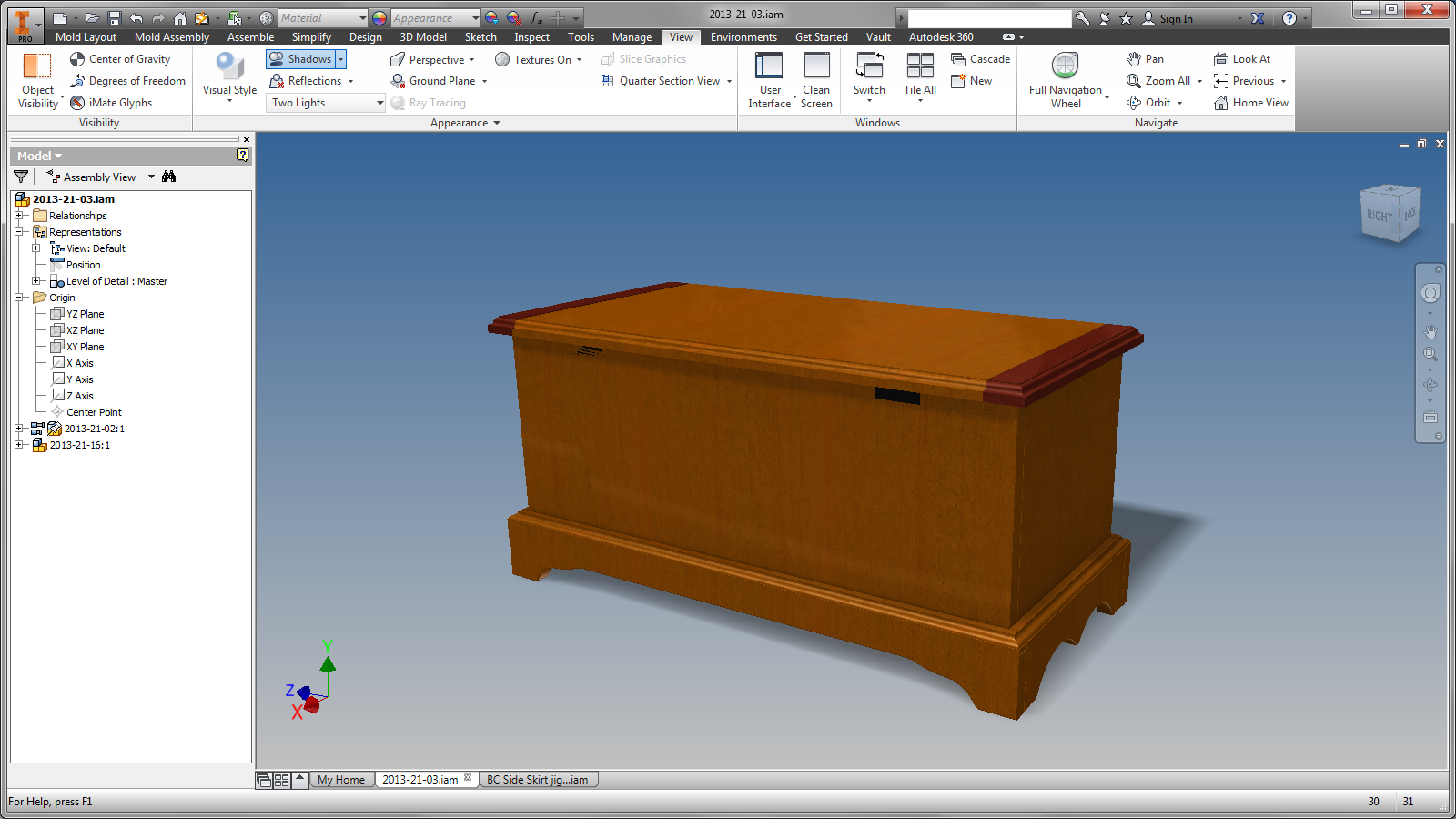
The blanket chest


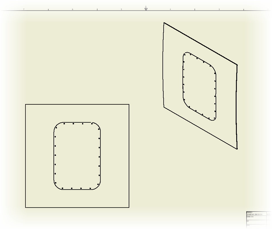
Part of that design includes a design feature, sometimes referred to as a "cloudlift" at the base of the part that can be cut using a jig to guide the router cutting them. 

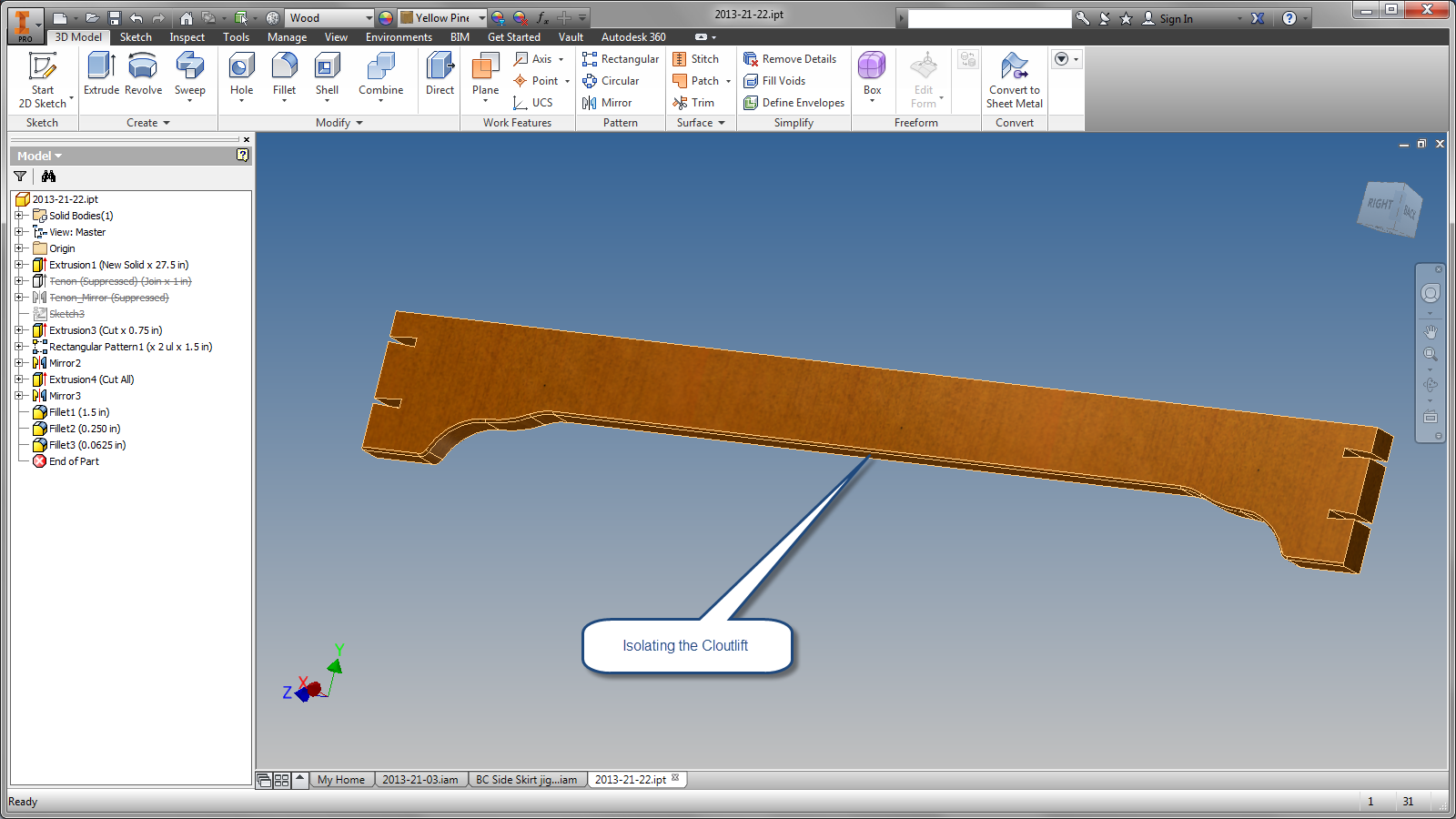
Isolating the part with the cloudlift. 

And that's the challenge, how could the shape be quickly transferred from the part being made, to the tool making it?  Sure, we could use the measure tool to and start transferring lines and arcs, but that's not efficient at all. 

So here's a solution!  I've built the jig to accommodate the part, all it needs is the cutout for the router to follow.


Now it's time to create the mating cutout.  First, edit the jig base and create a sketch where it's needed.

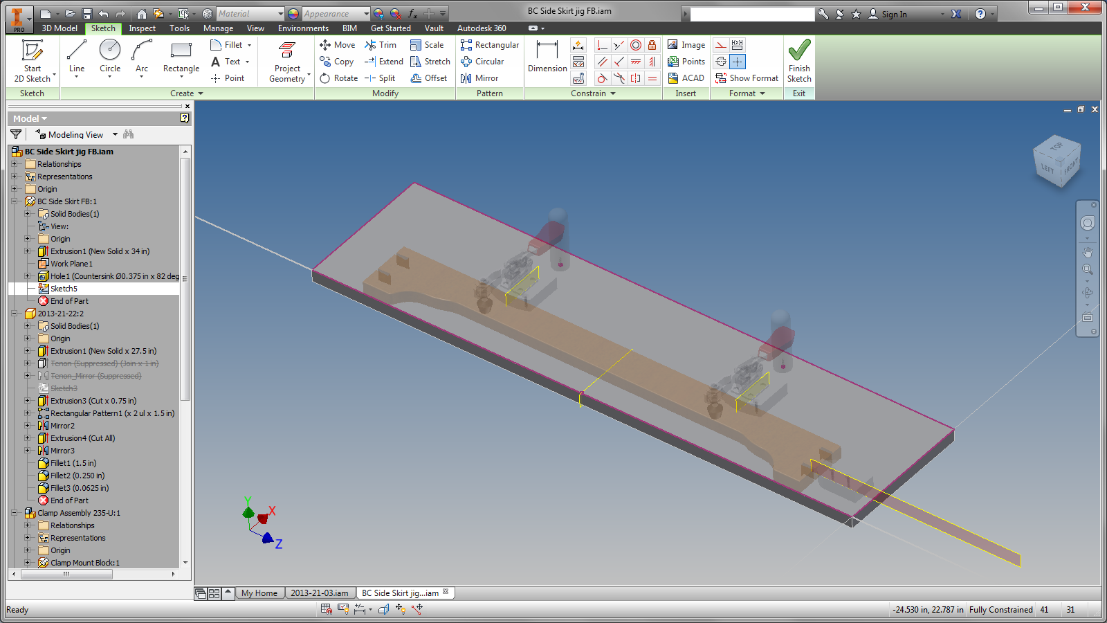
The new sketch is ready to go! 
Before projecting, here's a suggestion to make sure you're picking the correct edges,  Go to the view tab, and expand out the Appearance panel on the View ribbon.  Turn of transparency so the components that aren't currently being edited are solid.  It will make them easier to see in this case.

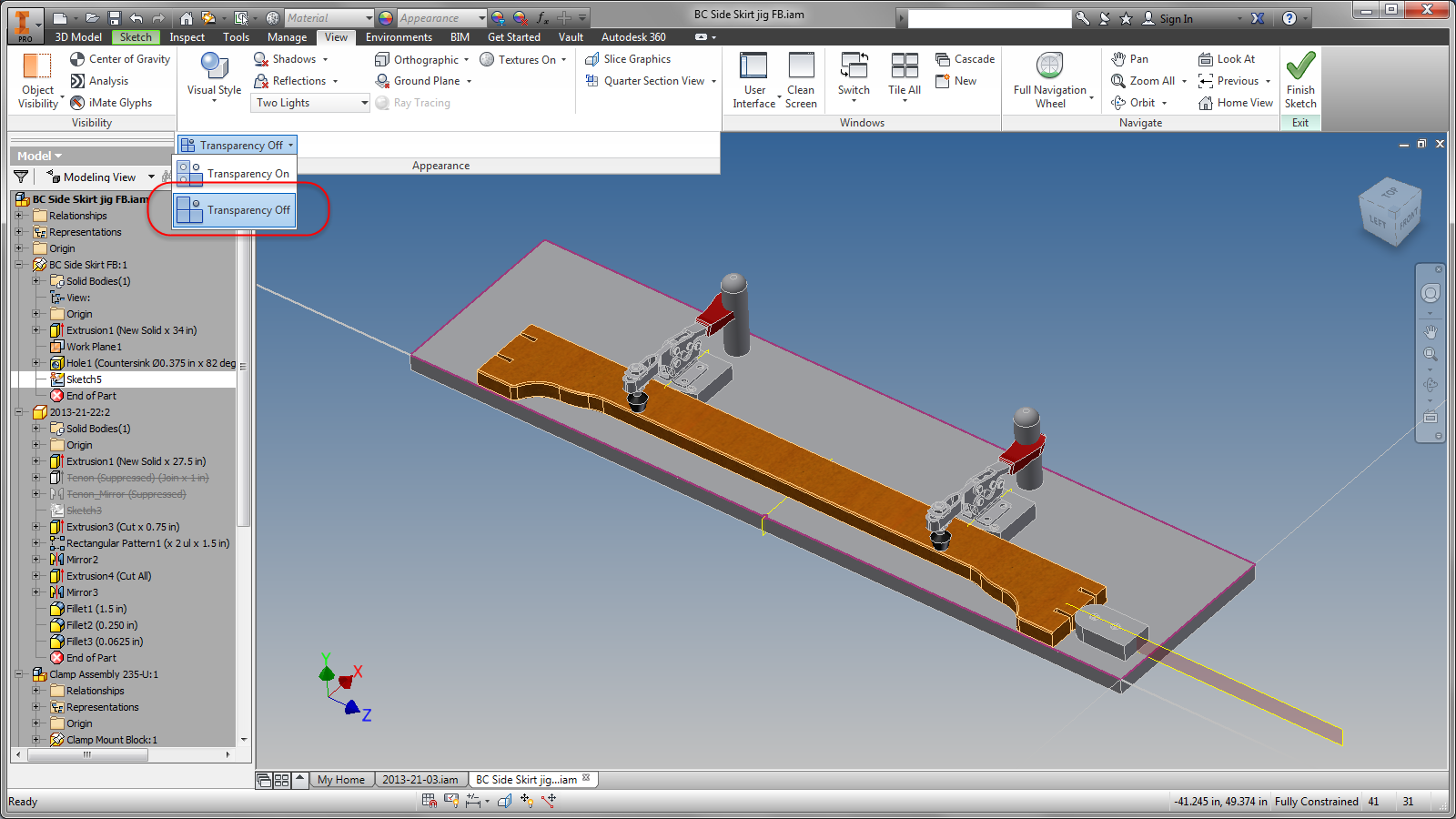
Editing the part with transparency turned off.

Now that we can see what we're doing, just use the Project Geometry to project the profile from the cloudlift on the part onto the jig.  

The sketch and part become adaptive by default.  

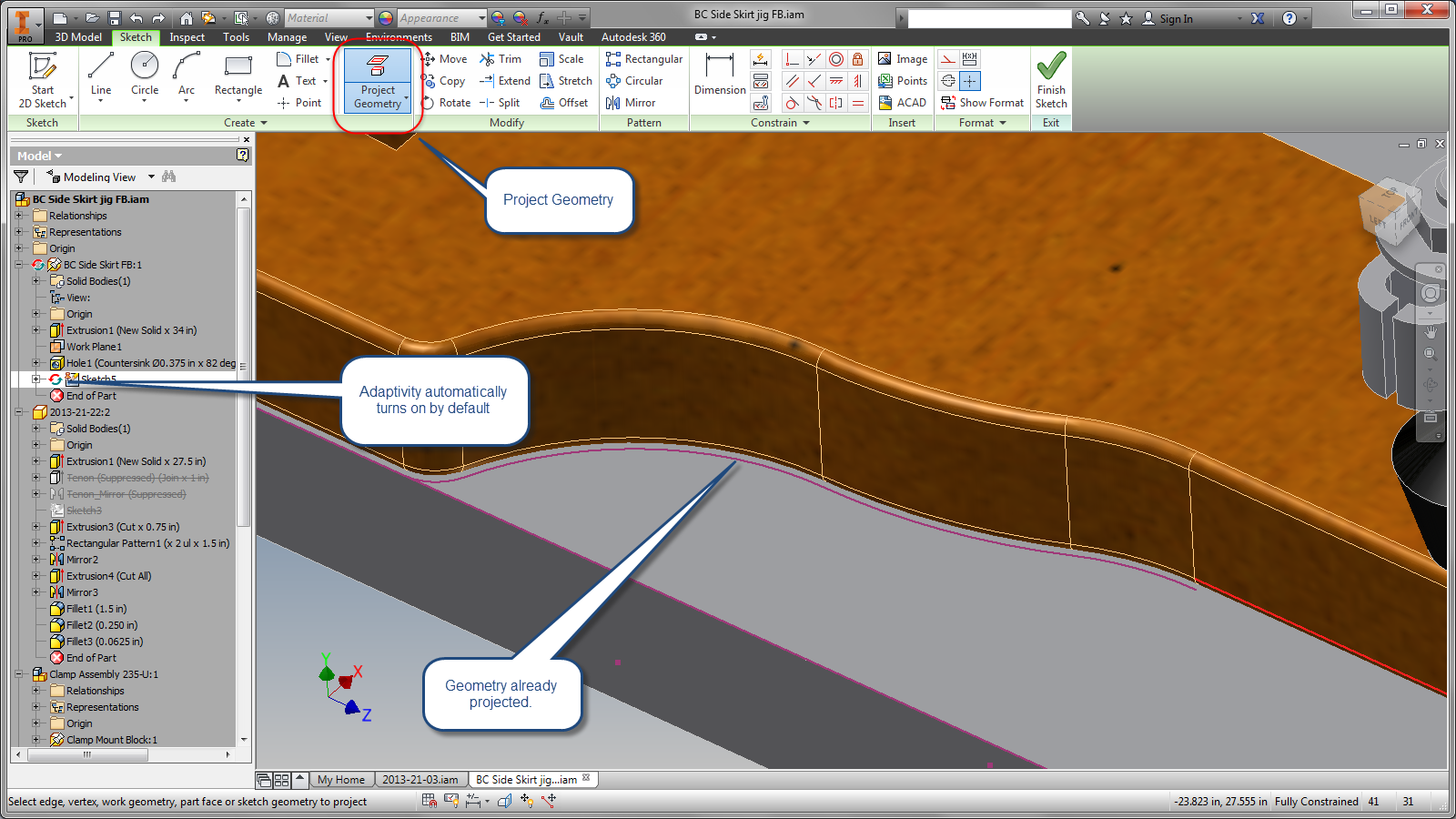
Projecting the geometry from the profile.
Note the adaptivity symbol in the browser. 

Now one more step.  In order to make sure the profile is closed, connect the open ends of the profile with a line.  


Once the loop is closed, extrude just like any other sketch. 


And now the jig contains exact profile from the part it's making!

But why go through this trouble?  What's the benefit/

For this application, the benefit is pretty simple.  If the cloudlift changes in size, the jig making it can change without the user having to make sure to size the mating part again.  And that can be a time saver if the part is in a fluid sate of design. 

First, the size of the driving part, the cloudlift profile is created.

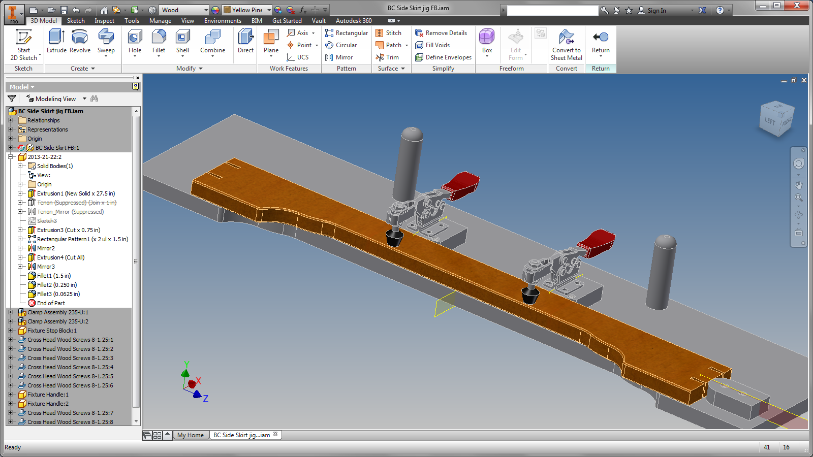
The part sizes are changed.


After finishing the edit, the jig, being adaptive, will match the size without user interaction! 

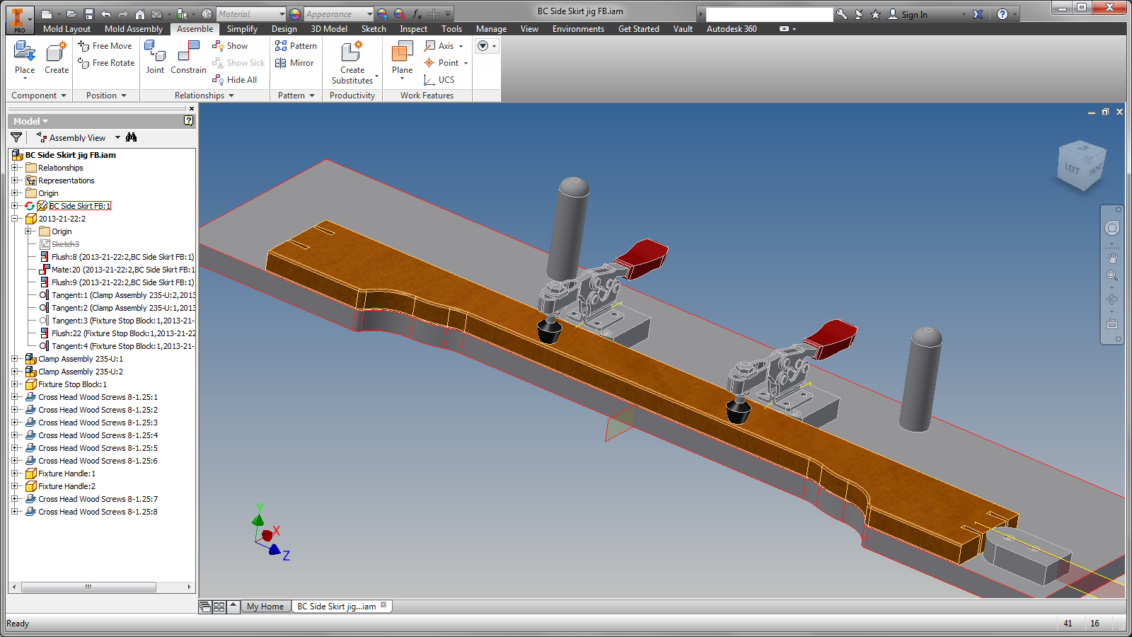
After finishing the edit the jig resizes.

So there we are, all done!  A case where adaptivity was the perfect tool for the job.

But before you Inventor power users light up the comment section, I'll speak to the fact that you don't get something for nothing.  

There is a price to be paid for using adaptivity.


  1. It will drive calculation times up.  Every time you update an assembly where adaptivity may be changing, Inventor is going to check to see if the adaptive parts need to update.  You may not notice it at first, but as the assembly gets larger and/or more adaptivity is used, performance can get seriously impacted. 
  2. Parts can update without user interaction.  That's right, one of adaptivity's biggest strengths can be its biggest drawback.  A part can update automatically.  Sometimes updating in such a way that it no longer functions.  If it happens without you realizing it, then you have a big problem. 
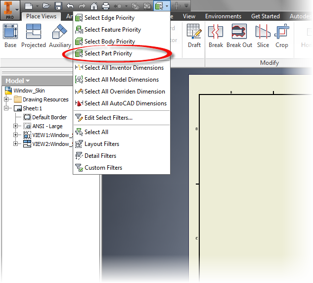
    1. As a result, it's a common practice to turn off adaptivity once the design begins to solidify.   Right click on the component in the browser and uncheck "Adaptive". The part won't update automatically until you turn it back on. 
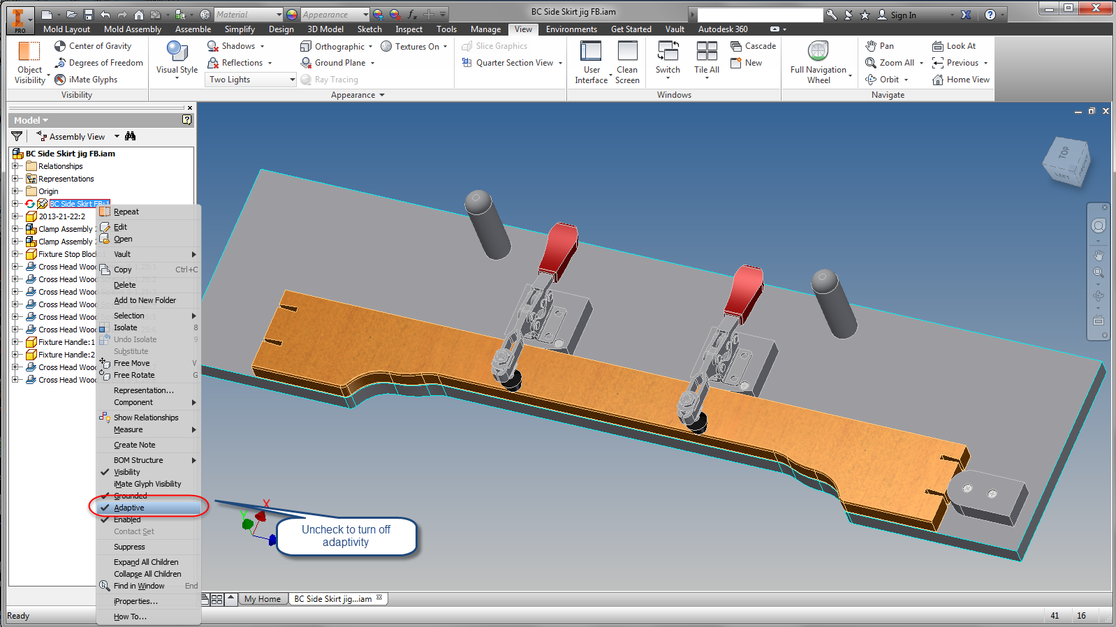
Turning off adaptivity.
In conclusion, Adaptivity can be a tool that can be extremely useful, but like any tool, one needs to know how, and where to use it.  While it's not the solution for every situation, when properly used, it can be a fantastic way to augment your designs. 

I'm afraid there's no video this time around!  I've been in a big time crunch the last couple of weeks, but I'm hoping to add in the next couple of weeks!  


Saturday, March 07, 2015

Using Copy Properties to Quickly Update Dimensions in Autodesk Inventor

The last few weeks have been comprised of Inventor drawings, comprised of even more drawings for me.

Part of that process included a lot of changing of decimal precision.

A common practice to change precision is to select the desired dimension and choose the dimension style from the format portion of the annotation tab.

Changing dimension style from the annotation tab.
This process works great, but if there's a lot of dimensions, it can get old fast.

Fortunately, there is an alternative to "sucking it up and dealing with it".

The tool is Copy Properties, and it does what it claims, it copies the properties of one dimension, and pastes them to as many other dimensions as you need.

To use this tool, start by right clicking on the dimension that has the formatting you want, and choose the Copy Properties tool.  

Using the properties of a source dimension.
If you  select the dimensions you want to copy the properties to, all the properties are copied.  That includes the tolerances, the style, even the text the text that accompanied the text

.
Pasting properties from one dimension, to another.

So before you select the target dimension, right click and choose Settings while Copy Properties is active.

Locating settings by right clicking while the tool is active.
This gives you an opportunity to choose what properties you want to copy from the source dimension.

The settings screen. 


Once you have the settings where you want them, choose the dimensions you want to transfer the settings to by clicking on them, and those properties are transferred!

You can pick individual dimensions, or even pick using a window!


Once you're done, just right click and choose Done, or hit escape to exit the tool.

Give it a try!

And check out the KETIV YouTube video  below to see it in action!  


Sunday, February 22, 2015

Shimming Your Knowledge - Adding Parameters to Text in Autodesk Inventor

In my last post, I mentioned that I've been doing a lot of work with Autodesk Inventor drawings.

I've found that this week, the trend has continued.  And while this can be a bit monotonous, it has given me an opportunity to blow the dust off some old tricks I've learned over the years.

One common thing I've seen is inserting a certain value into a block of text, such as note text.  These values can be things like sheet metal thickness, bend radius, or any other value that needs to be stated in the body of the text. 

A typical example.  I've added the radius dimension for comparison.

\It's never hard to type these values in, but if the value is just typed, then it's static.  If the value is changed in the model, there's no way to make sure that value updates, short of using the good old Mark 1 memory and Mark 1 eyeball.  


So let's take a look at how to automate that process.  Let's make the bend radius note update automatically. 

Start by editing the text the same way you always have.  Right click on the text and choose Edit Text

The editing screen

Once inside the text editor, focus on the set of bars just at the top of the text editing portion of the screen. 

From left to right, here's the information each pull down contains, starting from left, and working right. 

  • Component - Which component are you drawing the data from.  In this case, the model is named "Sheet Metal"
  • Source - Are you calling the parameter from the Model Parameters, or User Parameters
  • Parameter - The actual parameter you're placing. 
  • Precision - How many decimal places does the parameter contain. 
  • Add Parameter - This will actually put the parameter into the text. 
  • Special Symbols - Expand this menu to see common drafting symbols to place. 

The toolbar to add your parameters in. 

Clicking the Add Parameters button will add the value to the text, but inside of a gray box.  This tells you that the value is being read from an outside source. The sheet metal part in this case. 

Using the Add Parameter tool to make the magic happen!

Click OK to complete the operation. Now when that value changes in the model, the value will automatically be saved in the text!  


But there's one more thing.  What if you want to adjust the format even more?  To do that, right click on the text again, but this time, choose "Edit Unit Attributes". 

Now you can change the format of the units, including units, precision, and format.  In this case, I removed the leading zero, and added the unit string to make sure the units fit my standard.


All that's left to do, is hit OK, serve, and enjoy!  The units and leading zeros are gone, and the value on the drawing will update should the model change! 


And once that's done, you're all set!  Take a look at this tool, and see how it can help you!

If you prefer to see this information in video form, take a look at the video below!