I'll say straight up, I knew many of the steps, but I learned long ago to try not to "check out" of a presentation. There's always a gem if you know where to look.
Here's one I'm going to share with you! Embedding a model view on a website!
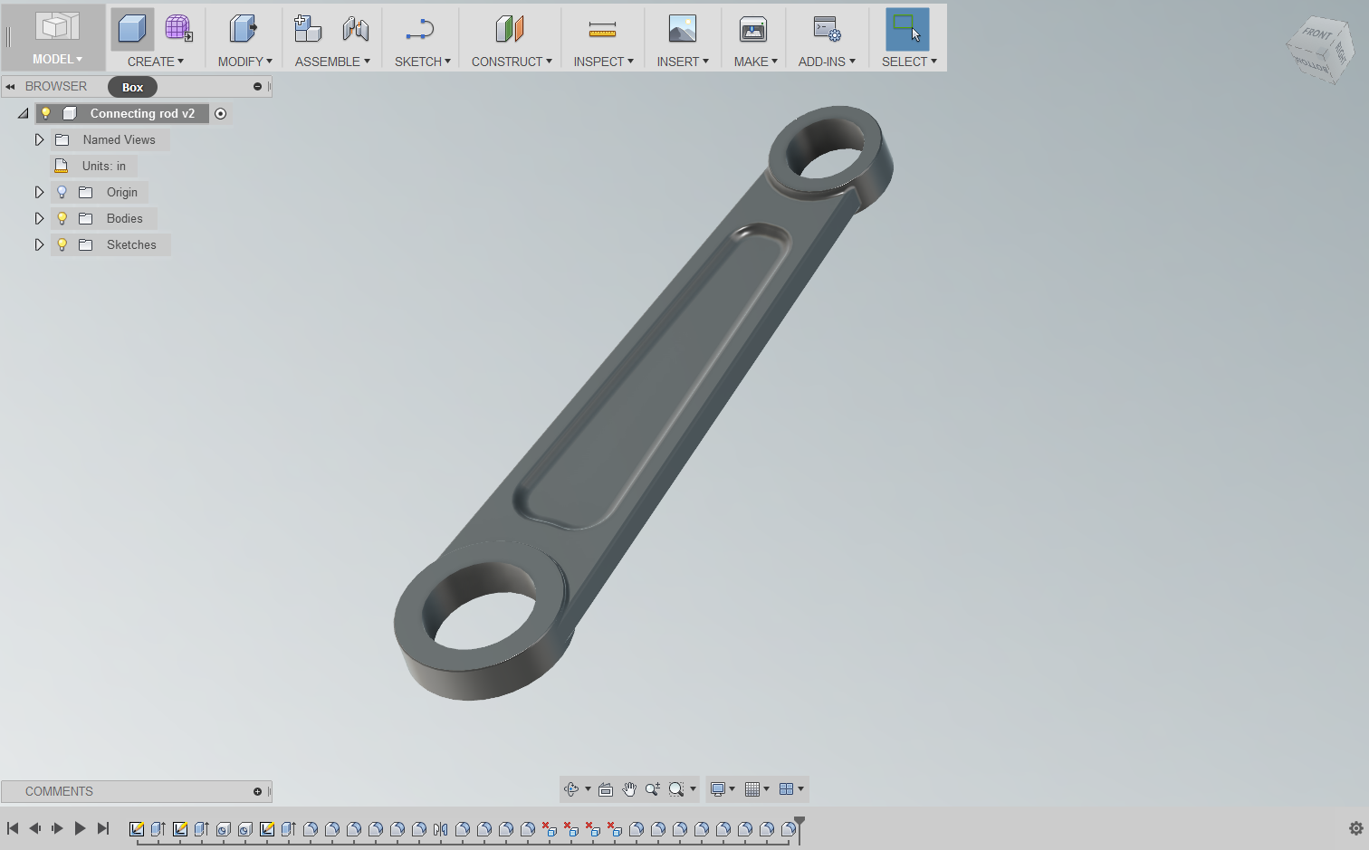
The first step is to locate the file you want to embed in Fusion 360. In my case, I'm going to share the connecting rod from my post yesterday.
But now, instead of just pasting in a picture,like I did above, I'm going to embed a 3D model view into the model!
The first thing to do is to locate the file in Fusion's data panel and click on the 'i' symbol to expand the flyout under the component.
Once you'll see the option to "Open Details in A360".
Clicking on the information icon
Click on that link and the file will open in A360.
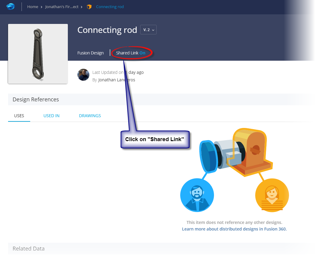
Once the file opens, click on the text next to "Shared Link" I've indicated in the image below. It will say "On" or "Off" depending on your settings
Click on the link in A360 for a pleasant surprise.
Selecting this link will open a window that will show you the options to Copy Link, Email, and Embed.
Since we're embedding, embed is the option we're going to choose!
Choosing the embed option
Once you have that, choose your size, and click the "Copy" button to paste the embed code into the destination.
Pasting the embed code
Once you have that, you're ready to go! You'll have a viewable file that you can embed in a webpage just like I have below!
Oh! One other trick! If none of the sizes presented by A360 work for you, locate the "Height" and "Width" settings in the embed code. You can tweak them to the size you want!
For my blog, I use 545 x 307, but you can always experiment with what works best!
In my previous post I mentioned that I was going to start diving headfirst into Autodesk Fusion 360. So taking advantage of a business trip to Detroit, that's what I've been using my evenings to do!
A nut plate I built in Fusion 360
You can find the part at this link
It's not that I've never used Fusion, but most of my work has been confined to a few hours here, followed by a months long hiatus. Rinse... Repeat.
In other words, I only dabbled in it.
It's a transition for sure! I've used Inventor since the year 2000. I know that program, and I'm comfortable in that program.
Having worked with a CAD program for that long, and putting some long hours into using it, it becomes tempting to keep it obsessively close.
It's my CAD! It's my precioussssss.....
But I told myself that I had to have an open mind, and judge Fusion 360 on its own merits. "Because its not Inventor!" is not reason enough to dislike Fusion.
So far, I've just been trying a little part modeling. I just found a few samples and began building models.
I didn't start out with something complicated, like the Eiffel Tower or a Boeing 737, I just picked a few simple parts, and started getting acquainted with Fusion!
A connecting rod I "Made up".
You can find this part at this link.
So what did I do? I just built! I built parts, used the tools, and just got used to how Fusion 360 works!
And so far, having tried simple part modeling, I like what I've seen. Many of the tools are similar to what I've used in Inventor, and I'm getting used to a few of the differences I've found so far.
I'll be diving deeper!
But I'm going to be looking at more than part models. I already have a few colleagues I may be collaborating on projects with, and I see potential for doing a little 3D printing.
And I've already tried my hand at sharing files on this blog!
So stay tuned! I'm enjoying the experience, and there will definitely be more to come!
I know I've been bad about posting, but I really do have a good reason!
For the last four weeks, I've been taking another Aviation Maintenance class at Mount San Antonio College. This class was "Induction and Fuel Metering Systems".
That meant studying carburetors, fuel injection, superchargers, and turbochargers, among other details.
It also meant working 6am to 4:30 PM Monday through Thursday, followed by class 5:30PM to 10:30PM, Monday through Friday.
In other words, a schedule fueled by momentum and caffeine, lots of days being the first out of bed, and the last to sleep at night, and being grateful for a supportive family who understands that I'm nearly invisible these four weeks.
But it's also incredibly rewarding, and dare I say fun, and as always, educational.
Why? Because I love the subject, and I love learning something new.
One of my projects was a 100 hour inspection of this RV-6's engine.
But classrooms are only the start. Life is the biggest classroom of all, and it loves to change the lesson midstream.
It's up to us to adapt to it!
So what does that have to do with InventorTales? Winds of change, that's what!
I no longer have access to a license of Inventor at home, which is where I write my blogs. And as much as I wish I could, I don't have the means to get myself a license of Inventor.
I could close up shop, and turn off the lights on InventorTales. After all, it's been a heck of a run!
Things are still a bit hectic for me. I'm busy with a new job, and I'm preparing to start up a new class in Aircraft Fuel systems.
I guess I just can't sit still!
I did want to share a short post on a funny experience at work the other day. Definitely a case of knowing more than I thought I did!
Many of the aircraft mechanics I know about refer to "Alodining" an aluminum part. It's a common practice to prevent corrosion on components made of non-ferrous materials.
You can find some more great pictures of parts having been "Alodined" at this link from Avon Electro.
In my Aircraft Maintenance Studies at Mount San Antonio College, I haven't had much hands on experience with the Alodining process, so it's been relegated to the "I need to read about that later" file, in my mind.
In another life, my design work, I've also worked with the "Chemical Conversion coating" of Aluminum alloys.
I knew that it was a protective coating that prevented aluminum as well. But there are many processes, and I knew what I needed to know to design parts.
Then one day, it all came together, with a bit of humor at my expense thrown in.
I had to read up on finishes for a totally separate process, and stumbled on to a document that spoke about chemical conversion coating shared by Chem Processing, Inc.
It was short, so I let my curiosity get the best of me, and read the article.
What was one of the first lines in the article?
"Chem Film, sometimes called Alodine or Iridite"
I had to laugh at myself. All this time, I had been dealing with the same processes, but not even known it.
Alodining, along with Iridite, are just trade names for chemical conversion!
In one paragraph that I stumbled on to via a web search, I had connected the dots, and realized that I had known more than I had. I was just missing one little link.
Ultimately, I found that I had known far more than I realized.
But what was the other big lesson I learned? Or perhaps, relearned?
Ask questions! For years. Yes, years! I assumed that I knew enough about Alodine and chemicial conversion coating.
And in many ways, I did. I could design fine with it, I hadn't used it "hands on" ye.
But if I had only asked one question... "What is Alodining". I could have bridged those gaps a long time ago.
Instead of having adequate knowledge, I would have had knowledge that could have set me a part, if only in a small way.
So that's what I share with you. Learn from my example, my mistake.
Ask questions. It is true when it's said the only dumb question is the one you don't ask!
I'll certainly be taking this lesson to heart.
One final note.
If you want to read more about Chemical conviersion coating yourself. Check out the article I found at Chem Processing, Inc here.
My father had many a humorous saying. One I remember came from his days as an aircraft mechanic for over 40 years.
"Mark it with a micrometer, mark it with a chalk, cut it with an axe."
It was a humorous reference to the futility we all encounter in our careers, whatever it may be.
I was reminded of this saying when I was reproducing a part that had a note indicating that a piece of standard extrusion was going to be "trimmed to fit.".
Technical translation? "Here's extra material, so you can make it fit in the field".
An example of "Trim to Fit"
But how do we represent that in the print?
In truth, there are several ways you could accomplish this. The one I present here, is just one idea.
First, offset a work plane the desired distance from the edge to be trimmed, in this case, I chose the maximum of .093 inches.
The first step is creating the work plane.
After the work plane is created, choose the Split command, and chose the "Split Bodies" option from the dialog box.
Make sure to choose the work plane as your split tool.
Splitting the bracket
Once that is done, create your drawing as you normally would. But you'll notice there's a bold line where the solid representing your bracket was split.
Now comes the trick! I'm going to make the lines representing the trimmed section dashed. This can be done by right clicking on the lines, and choosing "Properties".
Changing the lines from solid, to dashed
Once this is done, the part to be trimmed can be clearly seen!
The indicated lines are dashed!
There's the trick, but why use it over several other methods, such as creating sketch lines in the model, or drawing or perhaps only splitting a face?
Here are my reasons, I only ask you to consider them.
Splitting the part doesn't create any extra files, this approach keeps everything in the part (*.ipt) file.
Changing the lines is easy to do, the split creates a "natural break", which prevents having to create any sketch "trickery".
The split can be moved pretty easily, by changing the work plane's offset. This let's you represent the geometry more accurately if you desire.
So there are the reason I chose this method. Feel free to see what you think, and use this tip should you ever need it!
I've been quiet on this blog the last couple of months, but life has been busy, and blogging had to take a low priority.
The last few months have felt a bit like this! Without the fun!
But here I am, back to blogging! This week's tip is short, but I think that it's something that might prove valuable!
During my current adventure, I saw a trick. It's that trick that strikes so many of us. The one that makes you say "Why didn't I try that!"
Well, at least I can share it!
Did you know that you can drag PDF documents into Autodesk Design Review and have them be accessed from the DWF file?
Here's a simple description.
Here I have a NAS (National Aerospace Standard) screw with an "offset cruciform" head. I've exported the model from Inventor to a DWF file.
A DWF of an offset cruciform screw.
That part is well and good. But where you hear the word "standard", there's bound to be some sort of data sheet.
The NAS standard for offset cruciform screws.
And sure enough, there is a standard available on all the sizes, part numbers, etc. So what if you want to include this with the DWF?
Sure, you can attach both documents to an email, that will work just fine, and it's probably how most of us do it.
But what happens when the file will be downloaded, uploaded, file shared, and transported via USB?
There's always the chance that the files will become separated.
Did you also know that you can drag and drop the PDF into the desired DWF? All you have to do is drag it and drop the file into the browser. The steps are simple, but there are a couple of important things to remember
1) Make sure you're on the "List View" or "Thumbnails" view in the browser. If you don't, a new DWF file will be created from the PDF, instead of embedding the file in the current DWF.
Make sure you make the correct selections on the browser!
2) Now drag the PDF from Windows Explorer into the browser! That's it!
Drag and drop into the browser!
3) Now you're ready! the PDF will be converted and embedded into the DWF!
The DWF and PDF in one place!
So give it a try the next time a DWF is getting shared. You might find it helpful!
Last week, I finished up yet another class in aircraft maintenance at Mount San Antonio College. This course was "Materials and Science", and involved learning all manner of aircraft hardware, as well as material properties, and non destructive testing.
A photo posted by Jonathan Landeros (@jlanderos1973) on
Between my time of learning to identify different types of corrosion, tapping threads, and test material hardness, I had a chance to observe my fellow students, as well as reflect on how I approached and learned. I also came to realize that my learning went beyond the syllabus of the class.
So here, in 5 bullet points, are what Aircraft Maintenance Taught Me About Life
1) Don't Forget the Details!
One of my lab exercises was making a semi rigid tube. That meant sizing, bending, flaring, and assembling the fittings together. The instructor made a point to say that the tubes are critical for the flares to ensuring a pressure tight seal.
A photo posted by Jonathan Landeros (@jlanderos1973) on
I followed each of the steps carefully. My flares were the right size, the bends were spot on. I was feeling confident! So with my chest puffed out in pride, I plugged it into the test rig and waited for the instructor to be impressed and proclaim me a prodigy.
The instructor pressurized it to 1000 psi, our test pressure. He sprayed a soapy water solution to look for the dreaded bubbles that indicated a leak.... And.... bubbles....
Not a lot, but a slow and steady stream was parading out of the fitting.
The instructor pulled my tubing out of the test rig and looked into the flares. "You need to clean those up. I can see tool marks." He instructed. His experienced eye saw where the flaring tool had marked the inside of the flare. Barely noticeable, they were causing the minor, but unacceptable leaks in my line.
So I sat the tool bench with fine grit sandpaper for 20 minutes. I sanded until my fingers were sore, and the tips of my fingers numb. With much less bravado, I approached the instructor and tested the tube again.
This time it passed, successfully holding 1000 psi with out a single leak!
Lesson? Pay attention to the small, sometimes unseen details. They can save the day when the pressure is on.
2) Don't Confuse Speed with Purpose.
There were definitely two camps in class. There were the "fast movers", and the "slow movers". The fast movers jumped into the projects, got their hands dirty, and got to work.
The slow movers, were a bit more cautions. They read manuals, had discussions among themselves, and then picked up their tools.
Naturally, the "fast movers" had their projects submitted first. But then, something interesting happened.
The "fast movers" ran into issues. Hose fittings were over-torqued, dimensions were out of tolerance. Their progress was halted by the snapping sound of a tap breaking.
The fast movers began the process of reworking.
The "slow movers" on the other hand, while not perfect, ran into fewer mistakes, and were reworking their projects less. Eventually, just like in the fable of the tortoise and the hare, the slower group had passed the faster group. Their diligence meant they made steady, consistent progress.
A photo posted by Jonathan Landeros (@jlanderos1973) on
Lesson? Don't confuse activity with progress.
3) Good Students Memorize. Great Students Comprehend.
Our written tests were multiple choice, and the questions, which are defined by the FAA, are pretty standardized. That translated into a lot of going over questions, making sure you knew all the answers.
This was another place that the class divided into two camps.
One camp would drill on the questions, they could ask a question, and another student could answer with "B", and repeat the answer word for word from the test guide.
The other camp, would study at home individually, then just before the test, review the questions, talk about the answer, and then talk about why a given answer was the correct one.
Come test time, the second group consistently scored higher.
Why?
The instructor, knowing the answers are standardized, change the wording of the question. In turn, that could change the answer. That drilled in and memorized answer, "B", suddenly became "A".
A photo posted by Jonathan Landeros (@jlanderos1973) on
Many of the students that didn't understand the concepts and memorized the answer missed these questions.
The students who comprehended the concepts, could read the question, understand what was being asked, and could reason the correct answer based on the question that had been asked.
Lesson? Make sure you understand the fundamental concepts behind what you're doing. 4) Not Only Have a Plan, Have a Flexible Plan.
Our class had access to two mills for machining parts, and three drill presses. The mills, being more precise, were coveted machines.
Naturally, students who needed them would jump on them right away, stake their claim and work on their projects for as long as they could.
That left other students out in the cold.
Clever students quickly learned that the mills would often open up near the end of class, when "there wasn't any time to complete a project".
But the clever students would start their projects during that time, and use the mill to size their project, or center drill holes that would later be drilled and tapped.
This meant when they walked into class the next day, if the mill wasn't available, they would use the drill presses to complete their work, using the previous nights precision work as guide.
A photo posted by Jonathan Landeros (@jlanderos1973) on
As a result, they were still able to make steady progress through their project, while other students were still waiting impatiently for the mill.
Lesson? Have a plan, but be willing to adjust the plan to keep your goals on track. 5) Lessons Come from Many Places.
My instructor was fantastic. He had over twenty years of experience, he could relate his real, practical experiences to our class, making the lessons more meaningful. But he wasn't the only one who was teaching.
My fellow students came from all walks of life. I was one of two with engineering degrees. There were recent high school graduates, a machinist making a career change, and a retiree learning skills to maintain his own plane.
We were wonderfully eclectic!
Those with passion showed through. We learned from each other.
Students who had previous experience with machining helped those who had never tapped a hole. I learned how to hand form chromoly steel from a fellow student who'd done it before working on previous projects.
When the instructor wasn't available, the clever students found another way. Usually by learning from each other.
Lesson? Great Mentors are all Around You. Find Them
To end this post, I had a great time in class. I learned a lot about aircraft grade fasteners, fittings, materials, corrosion, and testing.
But it was also an amazing lesson in life. Making friends, working with them, and learning them, and having an opportunity to share a few lessons myself.
Most of all, I saw what my fellow students did to be successful, and I was reminded that success is not one great act, but a series of small acts repeated every day. It's trying, it's failing, and it's dusting yourself off and having the courage to try again.
Now if you excuse me, I have a few lessons to commit to heart, and maybe think of what my next class will be.
Here's the first post of 2016, and it's already been a busy year!
I've started with another class in aircraft maintenance. This time, materials and processes.
That means three straight weeks spending evenings learning about aircraft fluid lines, hardware, and heat treating.
It's a lot of work, but it's also fascinating. At least for me!
So my first week there I spent learning about all manner of fluid lines, I learned about semi-flexible lines, flexible lines, as well as the fittings that accompany them.
The hydraulics in a speed brake in an F-86 Saber (Taken at Planes of Fame Air Museum)
Just as important, was a lengthy lecture on how to install hoses properly to ensure they're effective and safe use!
Examples of the right and wrong way to install a hose. In short, don't twist the hose! (From AC43.13)
Like I said, it's fascinating for me.
But there are plenty of others out there, who may not give one rip about the differences in flares in an automotive versus an aircraft semi-rigid line. So what is the broader lesson to consider?
The tools to design is becoming more pervasive as technology allows design tools to the masses. Tools like Fusion 360 and Onshape have made 3D CAD available to people who only a few short years ago would have only dreamed of having access to that kind of design capability.
It opens up an entirely new world of potential of how people create things and build.
But I think that raises a new challenge. How do we design? We now have amazing tools for creating and making things. But that doesn't mean that we have the experience to use them to their full potential.
Those lessons can always be learned, but I don't think they should be learned in a vacuum. "Someone always knows more than you do." I'm told.
Mentor's come in many forms. I encourage you to find yours!
Sure, you can create a 3D model, we can even run an Finite Element Analysis (FEA) simulation and see how the stresses interact on our part.
But that doesn't help us know how to load a part. We can't always know that a hose should have 5-8% added to it's length to account for expansion and flex. Even today, software may not tell us that. Experience does.
There's no account for experience. Take this from a guy who has learned volumes from mechanics who have been doing their job for longer than I've been walking this planet.
You just can't beat that real world experience in my mind!
I can (and have) learned many a lesson from mechanics like the those repairing this F-86 Saber!
So what do I think the challenge as we take our first steps into 2016?
The "Internet of Things" rides on the backbone of the 'Information Superhighway".
We're fortunate enough to not only have the tools to design, but access to volumes of information on how to design.
Just look at resources like GrabCAD, and EngineersEdge. There are so many out there!
So as we begin 2016, let's design! Find a mentor, find a class. Let's embrace learning, and embrace our passions, whatever they are!
This week's post is short and sweet, due to a little craziness during the week, but I still hope you all find it enjoyable and helpful!
The simplest things can drive you crazy, One I encountered in Autodesk Inventor was a leader that seemed to randomly disappear. It would just stop in one place, and start in another.
There seemed to be absolutely no good reason for it.
Why is this leader cut off?
It can be really puzzling. The first time I encountered it, it completely threw me off. It took a little bit of clicking and dragging before it finally dawned on me.
If you study the image above, you can actually see it, if you know what to look for.
The text box covered up the leader for the balloon. Because of that, the masking "erases" the leader. Dragging the leader out of the box, or dragging the box away from the leader, cause the leader to reappear.
And the truth of the fact was I had been a little careless and "whipped" the text box and made it far larger than it needed to be.
Here, I've shrunk the box to give the leader room.
It's so simple, yet at the same time, it can be so frustrating. But in the end, it's really simple to fix.
So what's my suggestion?
Keep your eyes open, of course! But also be aware that dragging a huge text box, because "it doesn't make that big a difference" can be asking for trouble.
Why? It can cause a huge difference! But just be aware, and know what to look for, and a big frustration can be reduced to just an "oops".
Earlier, this month, I relived. something many CAD users have experienced.
Frequent freezing and crashing! The bane of any CAD jockey!
When a CAD system crashes, this is what designing feels like.
Let's paint a picture!
A natural first reaction is to blame the CAD system, then perhaps the hardware. Next may come the universe and any crimes you may have committed in a past life that have resulted in such Karmic retribution.
But there was one thing that blew everyone of those theories out of the water. Well, except for the Karmic retribution theory.
Inventor hadn't been having this problems before. It had been rock solid in the days, even hours.
So I traced back to what I was doing when the freezing and crashing started. What had I done?
It turned out, I had imported a step file that represented a gearbox. A coworker confirmed that he'd experienced the same thing on his system with that same model.
Smoking gun located!
This was my culprit. You evil, evil model.
Confirming the Symptoms
Opening and inspecting the gearbox by itself, There were a few symptoms the model exhibited that indicated it as our sick file. One of them may not be a problem, but together, things start to click.
1) The size was larger than I expected. It was about 5MB.
2) The file took forever to perform even simple operations. Things like placing constraints in an assembly, or creating a sketch in a part took several minutes to calculate.
3) Then aforementioned locking up and crashing.
At this point, I was sure I had found my culprit. The Solution
I recalled a discussion with a colleague many years ago, I remembered a corrupt step file that had caused crashing in her system.
In that case, there was a weird, intersecting face that crashed the system. The solution there had been to locate it and cut it away.
I actually tried that, but after about an hour, I hadn't located the problem. I even tried loading the file into Fusion 360, and still ran into performance issues.
It was time for a different approach, which I should have tried in the first place, in retrospect.
I downloaded a new model! But instead of a STEP file, I tried an SAT file.
And that worked! The system was stable again. It didn't crash again after that. The file was less than 1.5 MB,
It feels good to be under way again!
The Conclusions
Bad or corrupt neutral files exist. They're unavoidable. Like a game of telephone, they can be caused by bad translation, bad imports, or sometimes, just bad luck. I couldn't tell you the cause of this models issue, and ultimately,, my superiors didn't care.
They wanted the project moving, they didn't care about which corner of the model had an issue.
I encourage you to be aware that "bad models exist!"
Some CAD models just fall in with the wrong crowd....
Moreover, when your program of choice begins crashing, remember that crashes aren't always the fault of the program. Whether your using Inventor, Solidworks, Solidedge, or "My-CAD-Program-is the-best-and-if-you-disagree-your-wrong" CAD (We all know who those guys are!), look at what you did just before the crashing started.
It's always possible that whatever that was, a model, a bad constraint, sketch, whatever, is your "bad seed"
I'm at the end of the four day Thanksgiving Holiday in the United States, but even on vacation I was busy trying new things.
It's what I do...(Shrug)
For a couple of years, now, I've been hearing the benefits of Fusion 360. It's portable! It doesn't require a high power workstation! It's easy to use, and so on.
My old colleague, Jorge Fernandez, even built a 30 minute presentation on the benefits of Fusion 360!
And don't think I'm a detractor! I see the benefits, I fully acknowledge them. But what I haven't truly had yet, was an opportunity to realize those benefits for myself.
Our black cat, Scar, however, remains completely unmoved.
Scar the Kitteh is unimpressed by cloud applications like Fusion 360.
However, he does see immediate ROI in a fresh can of wet food.
This weekend, during the long weekend here in the United States, I had my opportunity to realize my benefits on a level that had a more personal impact.
First, a brief description of my situation.
I was working on a small cover that had to be light enough to be removed, but strong enough to be walked on. A constant concern was excessive "oil canning" of the material, where it would "pop" in and out like an old oil can.
If your old enough to remember theses, you know the "Oil Can Effect".
But time at work is precious. Development time, like anywhere must be kept to a minimum. And while there is value in development, there isn't always the time for development.
Many of us have encountered that before.
I don't mind playing with an idea at home. I do some of my best thinking at home, in solitude, with a cup of coffee in my hand.
My challenge is, I don't have Inventor at home. My installation is on a desktop machine, and I don't have a laptop husky enough to run the software currently.
But what I do have, is Fusion 360.
So over the course of my weekend, I built up a quick concept model,and ran a quick FEA to see what the design would do.
The floor model. There's even a grate texture to simulate perforated metal
The FEA analysis. I'm looking to see how much the floor deflects.
Is it a perfect design, no, it's a concept!
But what Fusion 360 allowed me to do was "strike while the iron was hot" when my ideas and inspiration collided in my brain, instead of when I walked into the office after a long weekend. Now I also have a more fully realized concept that I can share with colleagues.
When I walk in the office after vacation, I can talk about ideas. with a little more confidence, and with a little more visual aid.
This was my use for Fusion, a 3D notepad, repository for ideas, test station, and presenting tool, all in one.
Does this affect you? Perhaps, perhaps not. I leave that for you, as an individual to decide.
But do I think it's worth consideration, for my part, I have no doubts.
Oh! And one last post script. Here's the file I created, embedded from A360. I know the design isn't perfect, there's more tweaks I can make. But remember, it's a concept!
Creating and modifying prints often comes down to details.
Many errors I've seen (cough, made myself), are smaller, easier to miss details. One example, is forgetting to update a text field.
This is not the print you want to miss a detail on.
Just ask this engineer. He's got a tough boss!
These are often notes that are hiding in a corner in the drawing. A part number in a note is a prime example.
But what if I told you there was a way to set up your template with a field that automatically read in the part number? So that every time you placed a part in the drawing, the drawing automatically read in that part number.
There is, and this is how.
Start out by typing text, just like you have countless times in an Inventor drawing. But choose the settings indicated in the image below:
Here are the steps the image describes.
1) Start the text tool. You won't get far without this step.
2) Start typing! You'll need to get to the point where you're ready to insert the text.
3) Set the Type to Properties - Model. This makes sure that your reading the property from the model placed on the drawing.
4) Property - This is the property being placed in the text field. In my case, I'm using part number, but there plenty of others to choose from.
5) Insert - This is "pulling the trigger". This places the text in to the text field.
Next, you'll see carets with the property insert into your text editor. Part number appears in my case.
After this is done, complete typing the note you need. Once you hit OK. The text will appear on the drawing and the property's value will be read in. In my case, it's the part number 2015-48-12.
Should the property change, the field will update, wherever it's called out on the drawing, including multiple locations, if you have them.
In my example, I'll change the part number from 2015-48-12 to 15-1595-ABLE. Which, let's face it, part numbers, among other fields, can change.
Once the field is updated, the drawing will read that property from the model and automatically update.
There are the steps to get a property linked into a text field. To get real bang for your buck, add required fields to your template, and get rid of some of those repetitive, and easy to forget tasks!
And look at what other fields you can add. There are plenty to choose from!
I did create a video for this one using Autodesk Screencast. No sound, I'm afraid. But life has been keeping me *just* busy enough to keep me out of my little editing room!
In my post earlier this week, I blogged about learning how the orientation of the sheet metal flat pattern in Autodesk Inventor can affect the finish of the part that comes out of a machine, and how to flip the base face to make sure that the desired side was unblemished by the laser mill bed.
In my case, the finish being applied was a #4 finish to a stainless steel sheet. That was the nice finish that had to be protected.
Another view of a laser mill, and that finish destroying bed.
Now, this is the point where I confess something to all of you out there.
When I first heard #4 finish used in conversation, I was the guy nodding my head as if I knew of the #4 finish they spoke.
In reality, I had no idea what a #4 finish was, aside that it was special. While I was nodding knowingly, I was tilting my head like a curious dog on the inside. I endeavored to make a few Google searches when I got back to my desk.
Admit it! We've all looked like this at one point or another!
Not only did I find exactly what I needed to know about #4 finish, I found a wealth of information on stainless steel, I found definitions, information on composition, applications, corrosion properties. The list goes on and on.
I haven't even gone through the entire site yet! But I know that I will eventually. I'll refer to this site often!
I've already started downloading some of the handbooks for myself.
But if you're using stainless steel, thinking about using stainless steel, or you're a student wanting to learn about stainless steel, then this is a resource well worth considering.
And if you know any other great engineering materials, or anything at all, feel free to share with a comment!
And by the way! A #4 stainless finish is what you'd find on appliances, architectural wall panels, and tank trailers, among other things.
But now you have the resources to read that yourself!


