Find us on Google+ Inventor Tales

Saturday, March 07, 2015

Using Copy Properties to Quickly Update Dimensions in Autodesk Inventor

The last few weeks have been comprised of Inventor drawings, comprised of even more drawings for me.

Part of that process included a lot of changing of decimal precision.

A common practice to change precision is to select the desired dimension and choose the dimension style from the format portion of the annotation tab.

Changing dimension style from the annotation tab.
This process works great, but if there's a lot of dimensions, it can get old fast.

Fortunately, there is an alternative to "sucking it up and dealing with it".

The tool is Copy Properties, and it does what it claims, it copies the properties of one dimension, and pastes them to as many other dimensions as you need.

To use this tool, start by right clicking on the dimension that has the formatting you want, and choose the Copy Properties tool.  

Using the properties of a source dimension.
If you  select the dimensions you want to copy the properties to, all the properties are copied.  That includes the tolerances, the style, even the text the text that accompanied the text

.
Pasting properties from one dimension, to another.

So before you select the target dimension, right click and choose Settings while Copy Properties is active.

Locating settings by right clicking while the tool is active.
This gives you an opportunity to choose what properties you want to copy from the source dimension.

The settings screen. 


Once you have the settings where you want them, choose the dimensions you want to transfer the settings to by clicking on them, and those properties are transferred!

You can pick individual dimensions, or even pick using a window!


Once you're done, just right click and choose Done, or hit escape to exit the tool.

Give it a try!

And check out the KETIV YouTube video  below to see it in action!  


Sunday, February 22, 2015

Shimming Your Knowledge - Adding Parameters to Text in Autodesk Inventor

In my last post, I mentioned that I've been doing a lot of work with Autodesk Inventor drawings.

I've found that this week, the trend has continued.  And while this can be a bit monotonous, it has given me an opportunity to blow the dust off some old tricks I've learned over the years.

One common thing I've seen is inserting a certain value into a block of text, such as note text.  These values can be things like sheet metal thickness, bend radius, or any other value that needs to be stated in the body of the text. 

A typical example.  I've added the radius dimension for comparison.

\It's never hard to type these values in, but if the value is just typed, then it's static.  If the value is changed in the model, there's no way to make sure that value updates, short of using the good old Mark 1 memory and Mark 1 eyeball.  


So let's take a look at how to automate that process.  Let's make the bend radius note update automatically. 

Start by editing the text the same way you always have.  Right click on the text and choose Edit Text

The editing screen

Once inside the text editor, focus on the set of bars just at the top of the text editing portion of the screen. 

From left to right, here's the information each pull down contains, starting from left, and working right. 

  • Component - Which component are you drawing the data from.  In this case, the model is named "Sheet Metal"
  • Source - Are you calling the parameter from the Model Parameters, or User Parameters
  • Parameter - The actual parameter you're placing. 
  • Precision - How many decimal places does the parameter contain. 
  • Add Parameter - This will actually put the parameter into the text. 
  • Special Symbols - Expand this menu to see common drafting symbols to place. 

The toolbar to add your parameters in. 

Clicking the Add Parameters button will add the value to the text, but inside of a gray box.  This tells you that the value is being read from an outside source. The sheet metal part in this case. 

Using the Add Parameter tool to make the magic happen!

Click OK to complete the operation. Now when that value changes in the model, the value will automatically be saved in the text!  


But there's one more thing.  What if you want to adjust the format even more?  To do that, right click on the text again, but this time, choose "Edit Unit Attributes". 

Now you can change the format of the units, including units, precision, and format.  In this case, I removed the leading zero, and added the unit string to make sure the units fit my standard.


All that's left to do, is hit OK, serve, and enjoy!  The units and leading zeros are gone, and the value on the drawing will update should the model change! 


And once that's done, you're all set!  Take a look at this tool, and see how it can help you!

If you prefer to see this information in video form, take a look at the video below!


Sunday, February 15, 2015

Shimming Your Knowledge - Associating Text and Symbols to an Autodesk Inventor Drawing View


Lately, I've been doing a lot of work inside of Inventor drawings. During that time, I was asked how to make sure that all my text and symbols will move with a view.

If you've used Inventor for a while, you may have noticed that if you put in a text or symbols next to a view, they will stay behind if you want to move the view.

Everything looks right here.

After moving the view, the symbols stay behind.

It's usually not a big deal to move the text and/or symbols later, but there's always an opportunity to make a mistake.

And it's just a pain to move the symbols back to where they were!

But there is a way you can make the text and symbols move with the view, and that's to start off by placing the text and symbols using the leader options

Use leader text, and the leader options to place the symbols

If you place the text and symbols with leaders, the move with the view that they're attached to.


Place the symbols using the text as leader, and with symbols


But we didn't want leaders, right?

But that's okay.  If you right click on the leaders, you can delete the leaders, leaving the text and symbols behind. Just choose Delete Leader.

Add caption

The best part?  Even with the leaders removed, the association remains!  If the view is moved, the text and symbols now move with the view.

Now if the view is moved....


The text and symbols move with it! 

And that's how you can make sure your text and symbols update the way you want them!

For a video of the steps I've described above, check out the video below!


Friday, February 06, 2015

Shimming Your Knowledge. Using the Assembly BOM to quickly change Properties


Every Autodesk Inventor part and assembly contain valuable properties, called iProperties by the Inventor folks.  A savvy user can place critical information into iProperties.  These properties are passed from the part, into the assembly, and ultimately into the drawing.".

This information can be critical to making sure your finished product comes together properly.

I would be the first to tell you that, in a perfect world, any Inventor iProperties you need filled out should be filled out before you place the part in the assembly.  You should also set the material as well.


But I also admit that the phrase "Perfect World" comes with an asterisk and small print that reads. "You don't live in a perfect world".

With that being said, do I diligently set my iProperties and materials at the part, long before I place it in an assembly?

That's a big fat NOOOO!

This is usually what I've done.  The assembly has been created,
but the descriptions and materials haven't been set

That's right.  I'm as guilty as anyone out there.  I may even be more guilty.  That's me, sticking it to the man, breaking the rules.

I'll fill out those properties whenever I darn well please Muhahahaha! 

Why don't I take my own advise?  Part of it is bad habit.  I always want to jump into building the models. The fun part.  Documentation?  That's just as important, but it's also boring.

Is it a good excuse?  No.  It's just part of a bad habit I haven't quite shaken yet.

That leaves me with the self inflicted challenge of having to go back and return to my models at a later date, often when they're nearly finished, to add in the properties and set the materials I need.  That task is at best tedious.  At worst, it's time consuming and painful.

But fortunately, I know a nice tool that allows me to change my properties and materials from the assembly, in one convenient dialog box.

The result is like you opened each part and subassembly individually and made these changes, but you don't actually have to do that!

Who needs a perfect world!

The tool of which I speak is the assembly Bill of Materials, which can be found on the Management tab in the assembly.

Accessing the BOM Manager.
The Bill of Materials  icon is grayed out because the BOM
Manger is already open.
Expanding the assembly in the Bill of Materials manager, the fields available to be modified appear next to their components.

But what if you don't see the components you want?

To add columns, select the Choose Columns icon and drag the field you want and place it in the title bar.

Adding a column using the "Choose Columns" tool. 

To remove a column drag it from the title bar to the middle of the screen.  Release the mouse when the "X" appears.

Removing a column from the BOM manager. 

You can add or remove however many columns you need.

Now with the columns you want configured, now you can start filling out your iProperties, as well as selecting what materials you want for your components.

That's more like it! 

This is definitely a tool worth taking a look at, if you spend a lot of time editing properties and changing materials, this should be a big part of your toolkit!

I know there's some of you that prefer video tips!  If you do, I've created another video for the YouTube channel here!

Sunday, February 01, 2015

Shimming Your Knowledge - Quickly Switching Commands in Autodesk Inventor

SHIM (noun) - A thin piece of material, sometimes tapered, used for alignment or support.

In my last post, I decided to create a series of short tips.  Things that I can create quickly, but also that end users out in "the wild" can find useful in their day to day jobs.

And for this post, here's a little tip that, one could say, is "small but mighty."

It's common knowledge to most Inventor users that right clicking and choosing either the Cancel (ESC) or OK keys will exit a command.  Hitting the Escape key on your keyboard will also exit a command.

Ok and Cancel two ways of ending a command.
You can also hit the Escape key.

But did you know that's not necessary?  Did you know that you can invoke a new command from the ribbon, or hitting the hotkey for a new command will not only exit the command, but start a new one?

You can just start a new command, which will end the current command.

Try it!  It works!

And to see a video demonstration, take a look below!


Thursday, January 29, 2015

Lessons from a Simple Task - Using the Pause Command in a Batch File


Just today, I made myself work a lot harder than was ever necessary.  It started with a little bit of overconfidence, transitioned to about thirty minutes of frustration and swearing, and ended with success and a self deprecating laugh.

It started when I need to create a sample script to defragment an Autodesk Vault database.

How hard can it be, after all?  It's a short script.  It's only a few lines long anyway!

First, I grab the sample script from the Vault Help system.  You can find that in the defragment section at this link.

So now I have my command!

 Connectivity.ADMSConsole.exe -Odefragmentvault -NVault -VUAdministrator -VPadmin -S

This will fire up the command, but I still need to add my path information as well as my Vault name, I also need to add my administrator username and password.

REM - This Script Defrags the VAult Database
REM - Switch Legend
REM - Odefragmentvault ==> Command to defrag database
REM - -N Designates Vault name (this will vary machine to machine)
REM - -VU Vault user (must have administrator rights)
REM - -VP Vault password
REM - -S runs the script silently

D:\Program Files\Autodesk\ADMS Professional 2015\ADMS Console\Connectivity.ADMSConsole.exe -Odefragmentvault -NArduinna -VUadministrator -VP -S

IISRESET

So a little cutting and pasting I have the script I need.

Now, time for the test.

I run it once, it flashes on the screen and immediately disappears.

I check for syntax error, and I do find one.  Which I quickly fix.

But the script doesn't run.

I check my vault name, my administrator name.  My vault doesn't even have a password!

And for those of you with your mouse key on the comment button... I know it's bad practice not to have a password for the administrator!  But this is a personal Vault, on my laptop, which only I access.  So Thpppt! 

Finally, I have an idea.  One that I should have had a lot earlier than I did..

I add the word Pause at the end of my script.  So the script won't disappear when it finishes.

Let's take a second and think about this.

As soon as I run the script.  I see two words immediately. "Not Recognized".

I say phrases commonly found in garages, aircraft hangars, and factories everywhere.

The double quotes at the each end of the path are missing!

Wait! What? This is the problem! 
I look at my reflection in my computer screen.  "You Idiot!"  I shout, channeling my inner Ren.

It felt a little like this.
(From the Ren & Stimpy Show)
I should have known!  When running a command with spaces in it, you have to put the command inside of quotes.

If you don't , the script reaches the first space it sees, and tries to execute that.

So my batch file got to D:\Programs, tried to run that, and didn't know what to do.

In order to fix the script, I had to change the command line to look like what is below:

"D:\Program Files\Autodesk\ADMS Professional 2015\ADMS Console\Connectivity.ADMSConsole.exe" -Odefragmentvault -NArduinna -VUadministrator -VP -S

The quotes (in red) placed before D:\Program and after ADMSConsole.exe make all the difference in the world.

One more shot, and it runs fine!

So the final script looks like this.

REM - This Script Defrags the Vault Database
REM - Switch Legend
REM - Odefragmentvault ==> Command to defrag database
REM - -N Designates Vault name (this will vary machine to machine)
REM - -VU Vault user (must have administrator rights)
REM - -VP Vault password
REM - -S runs the script silently

"D:\Program Files\Autodesk\ADMS Professional 2015\ADMS Console

\Connectivity.ADMSConsole.exe" -Odefragmentvault -NArduinna -VUadministrator -VP -S

IISRESET

And that's it! It's ready to go.

Ultimately, what did I take a way from this one?
  • Use the PAUSE command to help analyze scripts.  Because it was a short script, I figured if I studied it, I could find my error.  But I didn't see the missing quotes. I missed the trees because of the forest, if you will. By adding the PAUSE command, I found my error in seconds.  Literally seconds! 
  • Slow down, you'll go faster.  Since this was an easy script, I thought I'd "bust it out quick".  Had I taken a little more time, and thought about my approach when I hit a snag, I may have solved it easier. 
  • Pay it forward.  I made a mistake.  One I should  have been able to avoid.  Here it is for you to learn from.  Hopefully, you can use this to avoid the pitfalls I found! 
On a final note, there are several administrative commands that can be scripted using batch files in Autodesk Vault. 

Learn more about them by following the link to the Autodesk site here


Friday, January 23, 2015

Shimming Your Knowledge- Changing Dimension Display in Autodesk Inventor.

SHIM (noun) - A thin piece of material, sometimes tapered, used for alignment or support.

I hectic schedule has required I take a different approach to my videos.

Instead of longer videos, which of course take more time to create, I'm going to create something shorter.  Originally I was going to call them "Microtips", but a friend suggested "Shims" as in the shims used in manufacturing.

But instead of using a these shims to adjust components for proper fir, you're shimming your knowledge for more productivity!

Now, let's use a this tip as a shim to adjust your knowledge for a better fit!

To start this out, here's one from the Inventor status bar, which is visible when a sketch is active, there are several buttons listed there, but for this tip, I'm just going to focus on the dimension display icon.

The dimension display menu expanded at the Status Bar
This icon changes how dimensions are displayed on your sketch, each providing you different information.

The options shown are as follows

1) Value - This option is the default for Inventor.  It shows the numerical value of the dimension, using the number of decimal places as set in the file's Document Settings.

Dimensions shown as value

2) Name - The Name options shows the name of the name of the dimension.  Notice that if a parameter is renamed, then that name is shown, instead of Inventor's default "dx" format.

Dimensions shown as name
3) Expression - This option displays both the dimension name, and the value at the same time.  If dimensions are linked to create mathematical expressions, these will be shown.

It also removes trailing zeros from a dimension, as well as showing additional decimal places for a dimension if it contains more than set in the Document Settings.

Dimensions shown as Expressions


4) Tolerance- If you've applied tolerances to a dimension, this setting will display the tolerances on screen. Additionally, any time a tolerance is evaluated at a value other than nominal, it will be underlined.  This is true of any dimension display setting.

For more on using tolerances in Inventor, see my earlier post!

Dimensions shown with Tolerances


5) Precise Value - This option removes trailing zeros from a dimension and showing the full decimal for a dimension if it exceeds the Document Settings.  It also shows the value of a toleranced dimension, even if it's being evaluated at a dimension other than nominal.

Dimensions showing Precise Value


And that's all for a short tip on Dimension Display!  I wanted to create something short and sweet.  I hope this helps!

I'm thinking of continuing to do this with the "little things" that are always a little hidden in Inventor.  If you think that's a good idea, throw in a comment below!

And a final note!  Here's a video describing the steps above!

Thursday, January 22, 2015

How to Attach Content Center to Vault 2015 through the ADMS Console!


Recently, I found myself installing Content Center Libraries into Autodesk Vault 2015.  It was standard operating procedure; I've done it a dozen times.

One thing new to the 2015 version of Vault, is that the Content Center Libraries are downloaded from the link here, instead of being provided on the media or in explicitly in the download.

The installer even states that when you're select it from the Install Tools & Utilities screen. 


No Content Here!  But there is a link to download it.

If you follow the instructions in the readme file, the steps aren't too difficult.  Just download the libraries you want, extract them, click on the batch file, and wait for the libraries to install. 
And if that’s how you wish to install the Content Center Libraries, go right ahead.   It works nicely!

Compressed Content Center on the left.
Extracted and ready to go on the right! 

But if you desire, there is an alternative way as well, if you prefer.

Start out by extracting the files down to the point where you can see the libraries in question, they end in the *.mdf and *.ldf extensions.  For example.  AI2015_Inventor ANSI.mdf, and AI2015_Inventor ANSI_log.ldf if you’re using the ANSI standard.

The ANSI libraries extracted.

Take these files, and copy them into the location with the other libraries for Vault, this location can vary, as an example, the location on my own machine is. D:\Program Files\Microsoft SQL Server\MSSQL11.AUTODESKVAULT\MSSQL\DATA.

In my example here, I've copied the ANSI, ISO, and Feature libraries.  But you can copy as many or as few as you want. 

The libraries copied into the Vault library locations

This will make the files available Vault, but Vault does need to be told to use them.
In order to tell Vault that it’s going to be using these files, open the ADMS Console, locate the Library folder. 

 Once you have that, right click on the folder and choose Attach.

Attaching the libraries you want. 
The libraries that have been placed directory appear, and you can add them to Vault by selcting them and clicking OK. 

You'll have to choose each individually, but this only takes a few minutes for a big library, or just a few seconds for a small library. 


You can add as many, or as few libraries as you need. I'd suggest skipping any libraries you don't want.

The libraries are loaded. 
There it is! An alternate way of loading the Content Center Libraries into Vault. 

But that does beg the question "So what?".  Why would you load the libraries using the alternate way, instead of the other way? 

The truth is, you can use whichever way you want.  It matters little in the grand scheme of things.

But if you've already have the extracted libraries, or you don't have the handy dandy batch file available, this can be a quick way to get where you need to be. 

I've even seen some clever Vault Admins use the Detach option as a way of "deleting without commitment" . They detach the library and make it unavailable to Vault, so users don't have access to it.

If at some point it turns out the users *do* need it, they just reattach it, without having to go through the process of downloading and extracting. 

So keep it in mind as just another tool you can use to make your life a little easier. . 

Sunday, January 11, 2015

An Exercise in iParts, and a Little Bit of Sharing!


Over the course of the last couple of weeks, I've been working on a little project, and I thought I'd share..

The part I practiced on was a NAS fastener series 1141-1148, in grip lengths from 1/16 of an inch to 6 inches. I built it with the intention of being usable as a library part, not to be one hundred percent accurate.

Since the part is a screw, with the same shape used in several different sizes, I decided to make it as an iPart.

The reason I created it was to refresh my memory when working with iParts, as well as exercise my knowledge of aircraft standards a bit. And it was good practice!

While I didn't learn (or relearn) anything particularly earth shattering, there are a couple of tips that I thought might be worth sharing.

1) Don't forget that you can use Microsoft Excel to edit your part tables.  Using Excel will allow you to using Excel to create equations, or just fill and copy series in the table.

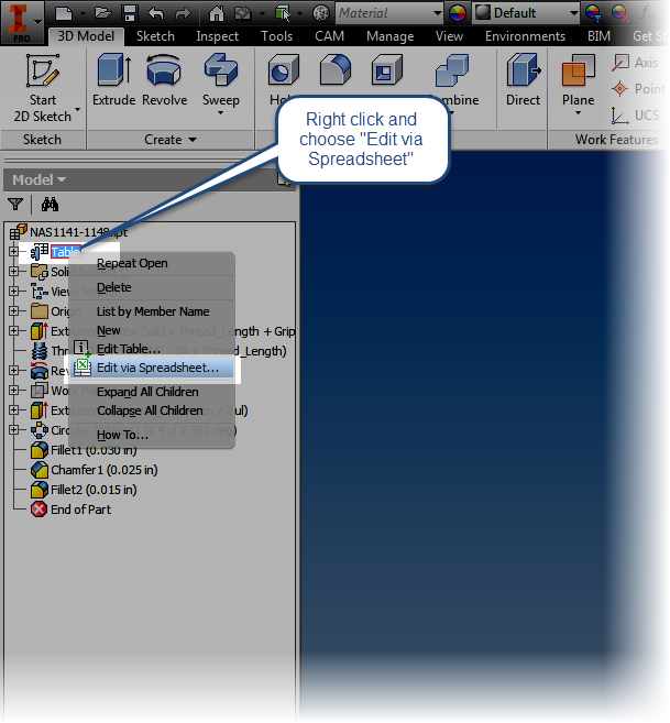
Using Excel can make editing the table *much* easier!

For example, looking at the sample part number 1145-03, the 03 means something.  It's the grip length of the screw in 16ths of an inch.  so 03/16 = a grip length of 3/16.

Looking at that from Excel, you have a formula!  Hello automating a repetitive task!

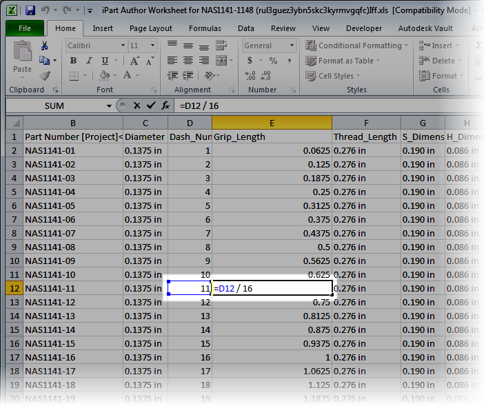
An example of an equation calculating a screw's grip length.

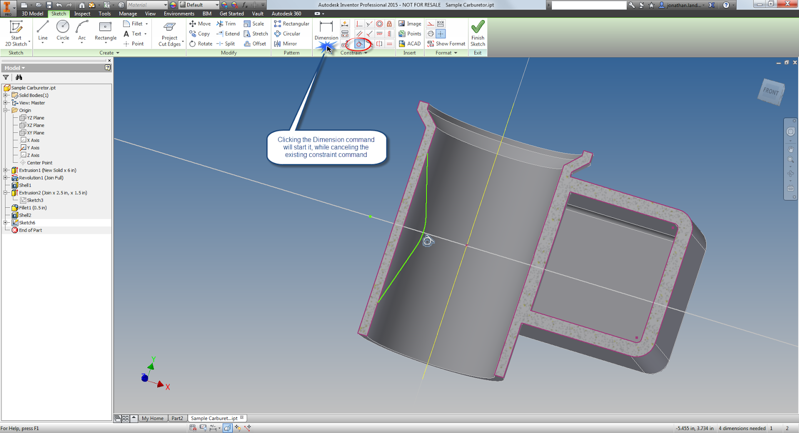
2) Don't forget that you can use Edit Member Scope and Edit Factory Scope to make adjusting iParts a little easier.

Edit Member Scope means any changes you make to the model only affect the active member.

Edit Factory Scope changed the entire factory, for example, when I need to add a fillet to the whole factory, I edited the factory scope.  When I wanted to modify just the width of a torq head (the sort of Phillips head looking part) for a single variation, I edited the member scope.

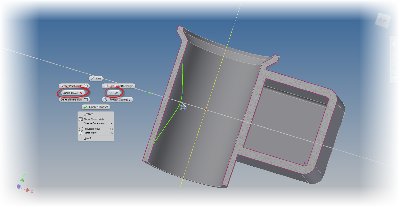
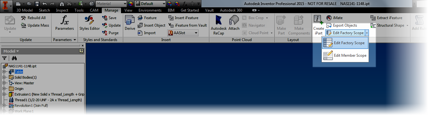
The icon for editing member versus factory scope.
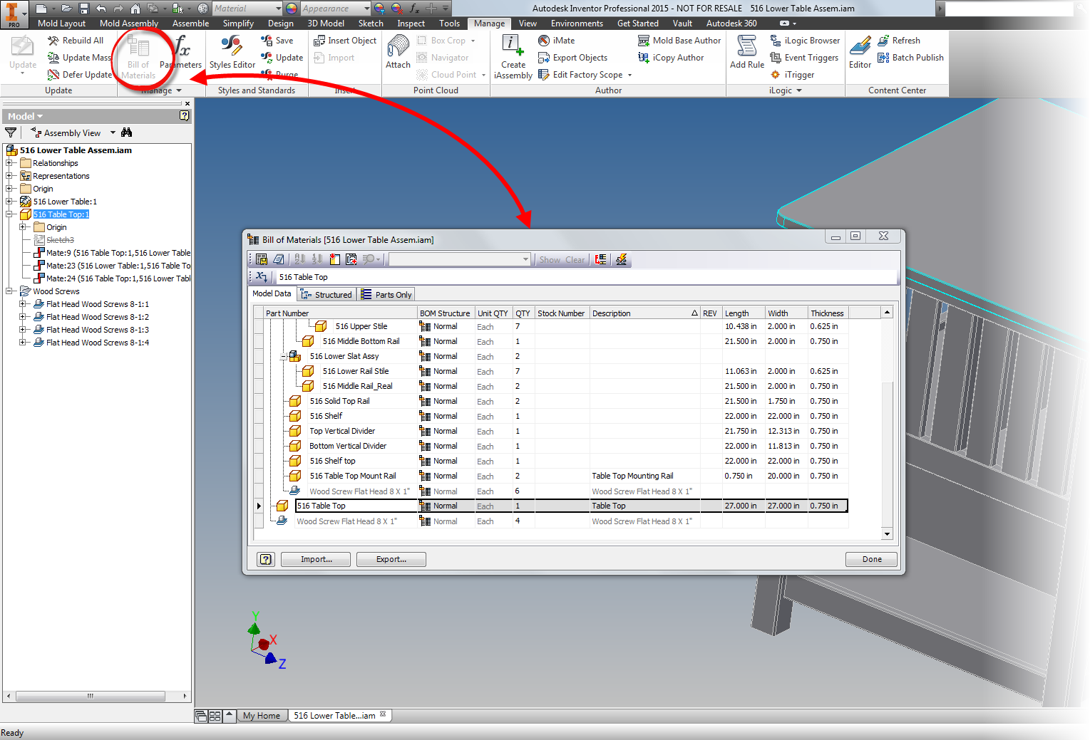
3) If you want to generate all the iPart members in a hurry, select them using Shift+Left Click.  Once the parts are selected, right click and choose Generate Files.

The computer may chug a bit, but it will build all the members required for this part.  Saving the trouble of doing it later.

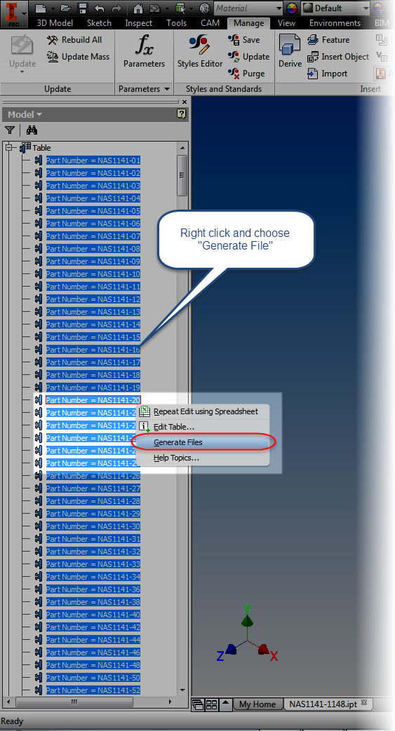
Selecting all all the members and generating all the files to generate all the files.
But after I was done working on this project, I decided that I would go head and share more than a few tips for this part, I'm just going to go ahead and share the iPart.

Of course I do have to offer up a few disclaimers, or at least advisories.

1) I've done my best to make sure that the values are correct.  But there is always the possibility that I suffered a case of fat fingers.  It never hurts to verify if you're going to use it for real!

2) This screw actually uses UNJF threads, not UNF like I've used in the iPart.  However, I designed this with the intention to be placed in assemblies, not to be accurate to the manufacturing level.  Since the default Inventor Thread table doesn't contain UNJF threads by default.

I do have a modified Thread.xls file with UNJ threads in it, but rather than talk people through modifying their Design Data folders, I decided to keep the part as universal as possible, since ultimately the part is only intended to be placed in an assembly.

But with all that said, take the part, use it, and enjoy it by downloading it from my GrabCAD account here!

If you don't have a GrabCAD account, you can download it from this link!

One final note, I found the technical information for the screw at the Coast Fabrication website.  It's got a wealth of information!


Wednesday, January 07, 2015

The Vault Service is Alive and Well! Why Can't I find the Data Management Services?!?!


Not that long ago, I ran into a Vault issue that I can only describe as truly puzzling, and more than a bit nerve wracking.

It all started out with the phrase that will strike fear into the heart of any Vault Admin.

"Vault's down.  Engineering is at a standstill." 

In Vault world, this is the same as hearing "Shields are down, weapons offline, and the dilithium crystals are nearly dead."

If you haven't heard this phrase, you're lucky.  If you have, trust me, it'll make you want to grab a red shirt and join the away team.

Left with no choice, I plunged in.  With Vault off line, many scenarios become a possibility, most of them not good.

After all, there's nothing more dangerous than engineers with free time.  It's like the A-Team, MacGyver and the MythBusters merged Voltron style, and then downed a gallon of espresso before going to work

The error being displayed by every single client was.


I reset IIS, the IT Admin rebooted the computer.  The same error appeared.  


I checked the standard issue things.

  • IIS?                           Running like a top
  • SQL Server?             Serving SQL just fine. 
  • Firewalls?                 Allowing traffic to pass. 
  • Log files?                  Nothing out of the norm... so it seemed....


Meanwhile, engineering has accepted a dare to use old office supplies, stale chocolate, and a 63 VW Beetle chassis to create an upgraded version of Rock 'em Sock 'em Robots.

Finally, after a bit of searching, the solution presented itself in the form of the link on the Autodesk support site here

A document came up, the first thing it said was check for the following in the Vault logs.  You'll commonly hear them called "Vlogs", and can be found using the instructions at this link.

Error: Soap Exception ( mesg-id = 635298001452597277 ) 
Exception: WebServiceError [800]
 
Exception(Inner): There was no endpoint listening at https://avia-srv3/AutodeskDM/Services/_impl/SiteService.svc that could accept the message. This is often caused by an incorrect address or SOAP action. See InnerException, if present, for more details. 
Stacktrace(Inner): 

Apparently, for reasons unknown, there was an SSL error that was preventing the connection to Vault.  I don't know all the ones and zeros that would cause this, and now with engineering trying to attach flamethrowers to their super-sized boxing game, we were focused on fixing the issue.

I try the first steps in the solution, which are:
  1. Start the Autodesk Data Management Server Console (ADMS) and go to Menu tools > Global Settings > Advanced Settings > Email.
  2. Remove the selection from the "Enable Compatibility with SSL" option.
But that doesn't solve my issue.  When I try to go to the Tools pulldown, I get the following error.


Fortunately, the solution at the link contains instructions for that case too!
  1. Use Notepad to open the web.config file from C:\Program Files\Autodesk\ADMS Professional 2014\Server\Web\Services .
  2. Change the sslRequired key from "true" to "false." 
I run these solutions, and for good measure, type IISRESET at the windows command prompt to bounce the service.

Now, both the IT admin and I hold our breaths and cross our fingers.

And then.....

It works! 

The first user logs in, then the second, and so on!  Cue epic symphonic music!

The IT admin and I congratulate each other.  If we had been in the same room, instead of working remotely, we might have hugged.

It felt like we had just successfully disarmed a bomb! 

But in the end, what's the point?  Why am I sharing this?  Will another user out in there find this helpful?

I don't know, you may never encounter this error.  And I'm the first to hope you don't.

But if this little tip resurrects just one users' Vault minutes before engineering completes their time traveling DeLorean.  If one user is able to take this and say "I was able to minimize downtime...."

If one frazzled CAD manager is just a little less frazzled, then this post did it's job!