Find us on Google+ Inventor Tales

Wednesday, May 25, 2016

Life with Fusion 360 - Copying and Pasting Components in Assemblies

My adventures diving into Fusion 360 continue.

As I've been adventuring into assemblies this week.  I chose a simple wooden table for my project.


The wooden table.  A work in progress.
I chose the project not for the modeling challenge, but as an opportunity to go through the process of building assembling, and documenting.

One of the first things that I encountered was the need to duplicate a part. That including creating a copy of the same part (a new instance), as well as creating a copy of a part in order to create a similar part.

I was pretty thrilled to find out that it wasn't difficult at all.

In my example, I'm going to duplicate the table legs.

To make the process simpler, the process of copying parts are nearly identical whether your creating a copy of an existing component, or using that component as the starting point for a new part.

To start the process, right click on the desired part and choose Copy.

Copying the component.


With the part copied, now it's time to paste the new component.  This is accomplished by right clicking in the modeling screen and choosing paste.

But there are two options.  Paste, and Paste New.


You may have already guessed that Paste will create a second instance of the component.  That is, and exact copy of  the existing component that will change with it's siblings.

However Paste New will create a new part, based on the old one, but it's entirely independent from the component it was spawned from.

But one of the other neat tools to check out are the handles that let you orient the part immediately after the component has been pasted into your design.

You can use the arrows for linear translations, the squares for planar translations, and the arcs for angular rotations.

Give them all a try!


Handles make it easy to position your parts
  There's also the option of typing in distances if you like.

The part after being moved.
Regardless, you can get the part positioned where you'd like.

All that's left to do now is right click and click OK, and then follow it up with precise positioning by joints later!

Hit OK to complete the move.
So that's it for the tonight.  My adventures in Fusion continue.  The deeper I go, the more I like its flexibility.

But there's still a lot more for me to learn, and I'll be sharing that as I go!  Stay tuned!

Sunday, May 22, 2016

Fusion 360 as a Viewer - Another Step in the Learning Experience

If you've spent any time at all looking into Fusion 360 you'll likely hear "the data is stored in the cloud" touted as one of it's big advantages.  

And it really is an advantage!  Here's one case that I've found where Fusion has helped augment Autodesk Inventor, but that's just the beginning!

Here's the end in mind!
What's the Scenario?

I was attending a design review for a small assembly, I may not be able to bring in my laptop, IT may not be able to install Inventor or Vault in time.

In other words, I may be on my own.  Time to think of a backup plan.  

Since I started out this post discussion Fusion 360, you may safely assume that Fusion 360 is part of the solution, and indeed it was.  

I also used A360 as a key part of my solution too. And that's where this story starts.

In short, I used Fusion 360 as my viewer. It was similar  to Inventor and I was comfortable using it. On top of that, the Fusion client is much simpler to install than Inventor, and can be done much more quickly.

Here are the steps I used to "get there from here".  In the interests of full disclosure, I'm using a sample file because the original file is proprietary.  Sorry, no peeks to that!

Here we go!

The first thing was to upload my assembly into A360 Drive.  Make sure to use the Assembly option under the Upload button.

Uploading into A360
Once that was done, browse to the folder containing the top level assembly, in this case, Engine MKII.


After hitting OK, there will be a few more questions to answer, the biggest one is which file is your actual parent file.  In this case, it's going to be Engine MKII.iam.

Choosing the parent file.  It's listed among it's candidates.

With the parent assembly selected, hit the Upload button, and the upload process will begin.

Ready to go! 

Now, the process of uploading to A360 will begin.  After a few moment, you'll get the indication that the assembly has been uploaded.


Time to Call Fusion 360

Now it's time to browse to the location you saved the file.  When you find the assembly, right click on it, and choose Create Fusion Design.

Creating a Fusion Design
Now, the converting process begins.

The upload is running

Give it a little time, and the conversion is completed.

And we're done! 
Make sure to refresh your project, and the newly created Fusion Design will appear.

The design is converted!


All that's left to do now, is double click on the file and you're ready to go with your new Fusion Design!

It's now ready to go in Fusion 360!

So what I ended up with was a quick way to use my design, without a heavy client install.  If necessary, I could even use the machine that was kept in the conference room!

I could navigate and control the visibility of parts.  Everything I needed at the time.

It was a great option that relieved a lot of stress.

Did you have any challenges uploading the file into Fusion?

I sure did!  I had some challenges loading the hardware, which was a combination of Inventor Content Center and iParts.  It wouldn't upload until I put it in the same folder as the components.

I don't know exactly why this is, but I'm going to poke around a bit more and see what I can find out.

Some of you may have a few questions on why I choose this direction.  Here are some answers to some questions you might be thinking of asking. 

Why didn't you use A360 as your viewer? 

I absolutely could have.   But I wasn't familiar with A360, so I made a decision to go with what I know.  Fusion worked great, but I know I can use A360 in the future.

Why didn't you use Project Leopard

Just like above, I knew it was an option, but I had less that 24 hours to make my decision, and very little experience with Project Leopard.  So I chose the path I knew.  Will I consider it the future?  Absolutely!

Did you use any of the review tools in Fusion 360?  

No.  I didn't.  And it's not because the tools don't work.  In truth, I haven't had a chance to try them yet.  The scenario simply didn't suit those tools.  But these tools do have my interest, and I'm looking for the opportunity to explore them!

And that's a wrap for this post... A little bit of what I've learned, and a few things to try in the future.

Saturday, May 14, 2016

Importing McMaster-Carr Models into Fusion 360

Most of us American based engineers have used, or are at least aware of, McMaster-Carr. 

If you haven't heard of them, they are a one stop shop for everything from nuts and bolts to urinals, and just about everything in between.

And not only can you get just about anything, you can get it as quickly as the same day!  

McMaster-Carr has saved the day, on the same day, more than once for me!

Now if you're a "well seasoned" engineer, such as myself, you might remember when the only way to look at McMaster-Carr's selection was a big yellow book that guaranteed about 50% odds of muscle sprain when lifting from the shelf to the desk.

Then you had to pick up a phone, which was most likely wired to the wall, and talk to a human being.
That was the state of the art of 1998.

The McMaster-Carr catalog.   Engineering resource,
workout implement, and potential zombie apocalypse weapon. 
Then, in the 1990s, we began becoming aware of this thing called the internet, and McMaster-Carr got a website.

Engineers everywhere rejoiced.  Now there was no risk of physical injury, and we could order the parts we needed while still tanning by the light of our old cathode ray tube monitors.

A screen capture from the McMaster-Carr page

Now engineers could spend money on expensive mechanical gadgets faster and more efficiently!  And many parts had models that could be downloaded and imported into your CAD models!

A page showing the download page
They've even recently come up with an app for Android and iPhone, that lets you purchase your items using your mobile device.

The McMaster-Carr Online App


It's perfect for us introvert engineers that don't feel like talking to people!

So where is this all going?

Earlier this week, I attended an Autodesk Fusion 360 event at Hollywood 3D Printing, where I got to meet, other Fusion 360 users, and see how those users are using the new technology.

And while there were many interesting things, one feature caught my eye.

A direct link to McMaster-Carr right inside of Fusion 360.

Here's how it works.  I'm using a simple example of an oil pressure relief valve that I was modeling for a little Fusion 360 practice.  I've modeled a body that would represent the engine case, as well as the poppet in red.

The oil relief valve model in Fusion 360


But I need two things, a spring, and a set screw to hold the spring in.  Instead of creating models, I'm going to insert them from McMaster-Carr.

Here we go!

First locate Insert McMaster-Carr Component Component from Fusion 360's Insert Menu.

Locating the shortcut to McMaster-Carr.

When you choose that option, Fusion 360 will open the McMaster-Carr website.  But the key is it will open inside of Fusion 360!

The McMaster-Carr catalog in Fusion 360
Now it's just a matter of finding what you want, choosing the CAD icon, and downloading the model.

Choosing a CAD model from the catalog. 

But the key is that it downloads right into Fusion 360!

Saving the model to insert into Fusion 360

Choosing the Save will insert the model directly into the Fusion 360 model without having to downloading to a location and import, like we've had to do in the past.

Inserting the set screw
Now the model can be inserted and constrained like any component.

Just add the spring, and the model is done!   By using the catalog from McMaster-Carr, the parts I can quickly import parts that I know I can order!


What's another bonus?  When you create a bill of materials, you get the part numbers, as well as the descriptions for those parts.  That means no retyping of component descriptions and reduced risk of making a mistake.

So if you're using Fusion 360, or thinking about it, take a look at this functionality.  I think it's one you'll find is well worth it.

And I'd also encourage you to take a moment to think how far technology has come.  It was less than 20 years ago that I was writing down numbers out of a catalog, calling an operator at McMaster-Carr, and reciting numbers over the phone.

This was done after I built my own 3D models in Mechanical Desktop, because McMaster-Carr didn't have any for me to download

Now, it can be inserted directly into your 3D with models from the McMaster-Carr website, where part numbers and descriptions automatically populate your bill of materials, and ordered via the website.

How far we've come in a very short time.

And if you'd like to see a few pictures I took at the Fusion 360 event, check out this link!

Sunday, May 08, 2016

Learning Fusion 360 - Building a 20 Sided Die

Many, many moons ago, a friend of mine asked me to model dice for a local gaming store, Dicehouse Games.  The trickiest of these was the 20 sided die, like I have pictured here.


Feel free to check out that post here,  I'm going to focus on my Fusion 360 experience here.  I found the steps were actually very similar.

Consider it a little bit of a musing about how my previous experience in Inventor compared to creating the die in Fusion 360.

The initial steps were the same, I created three rectangle on the XY, XZ, and YZ planes with a ratio of 1:1.618.  Just like before, I referenced this Wikipedia article here.

You may hear these referred to as the "Golden Rectangle".

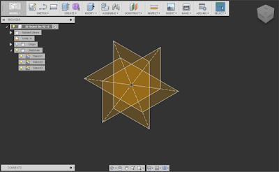
The very skeleton of the 20 sided die.  The golden rectangles with a ratio of 1:1.618

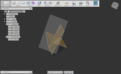
Next, came the "how does Fusion 360 do it?" moment.  That meant building some workplanes using the "Plane Through Three Points" tool, and creating a sketch on that workplane.

I sketched three lines, using the three points of the rectangles as shown below.

The three point workplane with a sketch created on it.  One of the "Golden Rectangles has its visibility turned off to reduce "cluttter". 
To keep my process as simple as possible, I also created a boundary patch from the triangle.  It makes it easier to use turn off the visibility of these objects when things get a little cluttered.

The same model, with the boundary  patch added. 

Now there's a lot of "rinse and repeat" type of steps.  More 3 point workplanes, more sketches, and more lines defining triangles.

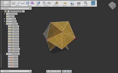
More boundary patches begin to define the "skin' of the die. 
But as I added more patches, I realized I could tweak my process a little bit, and make the operation go a little more easily.

I realized, I had enough patches where instead of using the Plane Through Three Points Workplane tool, I could use the "Plane Through 2 Edges Tool".  This was because I now had adjacent patch edges I could use to help me .

Fewer picks, faster process.

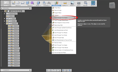
Once you have a few patches created, you can make better progress! 

There was more repeating of the now modified steps.  More sketches, more patches, until at long last, I had a complete skeleton of the die made with workplanes, surfaces, and boundary patches.

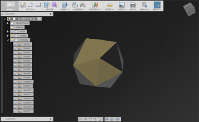
The die skinned with twenty different patches. 
Now what's left to do is to to make a solid out of it, using the "Stitch" tool.   This seals the 20 surfaces into a solid.  I now have a twenty sided solid!

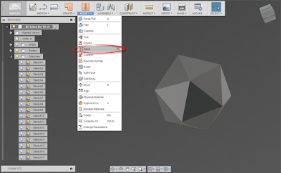
The now stitched die!  Note I changed my background color to make the now solid die a little more clear. 

After this, comes the long process of adding numbers.  This will take a while.  There's no real getting around that.

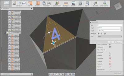
Sketching in text.  Fusion 360's drag and rotation tools really helped this process. 
There was a lot of sketch, extrusion, sketch extrusion, going on here.  But finally the whole die was modeled!

Now, I added a little color.  I had experimented with orange, but went for red this time.

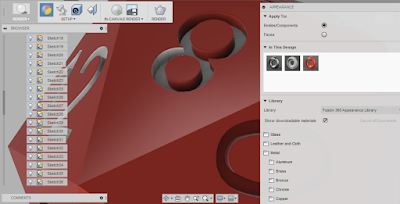
Dragging color onto the die using the render environment. 

After quite a bit of dragging, the colors are all done!

After adding fillets to smooth the rough edges, and the die is done!
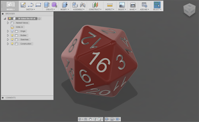
The die completed! 
So after that exercise, what did I learn, and like about this exercise?

1) Neat little workflow in sketching! 
When you start a sketching tool, and there isn't an active sketch, Fusion will start a sketch for you.  Thanks for the help with that!!

2) Drag and drop. I like it.  That is all. 
Fusion's push pull and rotation tools on the "drag and drop functionality really came in handy.  It was nice to rotate and move text by dragging with the grips.  It made that tedious task go a little faster.

3) Keep an open mind, you might need to try a model a couple of times to get it right.
I started one model, then threw it away when I realized I wasn't making it as efficiently as I could.  I get we can't all do that, but make sure to look for the lessons to improve your flow for the next time.

4) Take the lessons you learned from one program, but don't take them too seriously.
We've all heard the frustrated user say "This program doesn't do it like MYFAVORITECAD!"  Well, no. It's not MYFAVORITE CAD.  Maybe it doesn't better, maybe not.  But at least be open to the changes before you dismiss them!


So my adventures in Fusion 360 continue.  I'm enjoying them, and I'll continue looking for ways to improve my skills set.

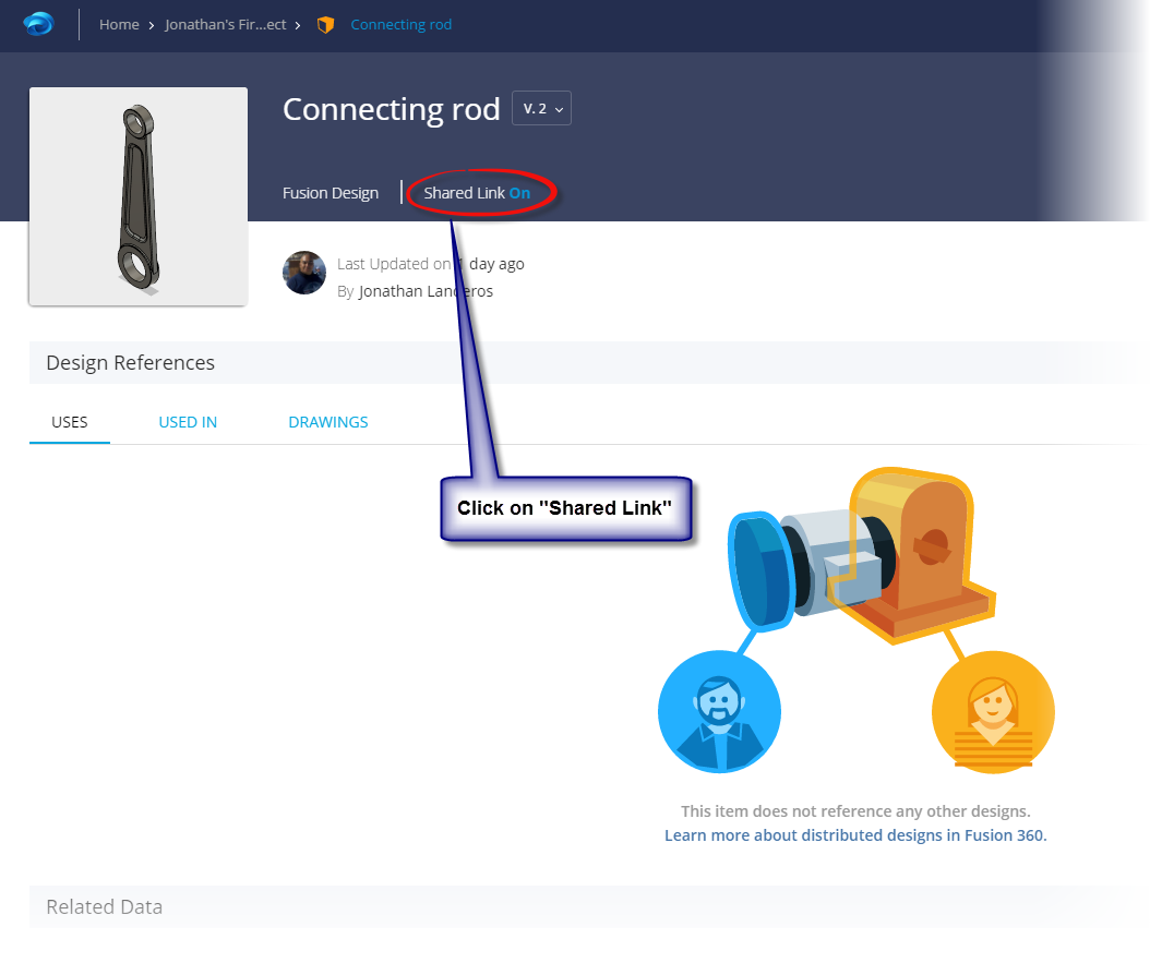
And if you'd like to take a look at this model yourself.  Here's a link to download it.  That's right.  Yours for the taking, enjoy!

I'm considering writing some posts describing how I built the die in a little more detail.  If you're interested, feel free to throw in a comment!


Thursday, April 21, 2016

A Little More with Fusion 360 and A360 - Sharing and Embedding

Just past Thursday I attended an Autodesk Fusion 360 Meetup in Novi, Michigan.

I figured it was a little bit of serendipity, that I just happened to be in in Novi for some PLM360 training.

Attending the event was a must.  A moral imperative, if you will! 

So I sat down at the event with my laptop and began watching the presentation.


Watching the presentation and building models! 

I'll say straight up, I knew many of the steps, but I learned long ago to try not to "check out" of a presentation.  There's always a gem if you know where to look. 

Here's one I'm going to share with you!  Embedding a model view on a website!
The first step is to locate the file you want to embed in Fusion 360.  In my case, I'm going to share the connecting rod from my post yesterday. 


But now, instead of just pasting in a picture,like I did above,  I'm going to embed a 3D model view into the model! 

The first thing to do is to locate the file in Fusion's data panel and click on the 'i' symbol to expand the flyout under the component. 

Once you'll see the option to "Open Details in A360". 

Clicking on the information icon
Click on that link and the file will open in A360. 

Once the file opens, click on the text next to "Shared Link" I've indicated in the image below.  It will say "On" or "Off" depending on your settings

Click on the link in A360 for a pleasant surprise. 

Selecting this link will open a window that will show you the options to Copy Link, Email, and Embed.  

Since we're embedding, embed is the option we're going to choose! 

Choosing the embed option
Once you have that, choose your size, and click the "Copy" button to paste the embed code into the destination.

Pasting the embed code

Once you have that, you're ready to go!  You'll have a viewable file that you can embed in a webpage just like I have below!


Oh! One other trick! If none of the sizes presented by A360 work for you, locate the "Height" and "Width" settings in the embed code.  You can tweak them to the size you want!

For my blog, I use 545 x 307, but you can always experiment with what works best! 

Feel free to edit the embed code. 


Fusion 360 - An Update on My New Experience

In my previous post I mentioned that I was going to start diving headfirst into Autodesk Fusion 360.  So taking advantage of a business trip to Detroit, that's what I've been using my evenings to do!

A nut plate I built in Fusion 360
You can find the part at this link

It's not that I've never used Fusion, but most of my work has been confined to a few hours here, followed by a months long hiatus.  Rinse... Repeat.

In other words, I only dabbled in it.

It's a transition for sure!  I've used Inventor since the year 2000.  I know that program, and I'm comfortable in that program.

Having worked with a CAD program for that long, and putting some long hours into using it, it becomes tempting to keep it obsessively close.

It's my CAD!  It's my precioussssss.....  

But I told myself that I had to have an open mind, and judge Fusion 360 on its own merits.  "Because its not Inventor!" is not reason enough to dislike Fusion.

So far, I've just been trying a little part modeling.  I just found a few samples and began building models.

I didn't start out with something complicated, like the Eiffel Tower or a Boeing 737, I just picked a few simple parts, and started getting acquainted with Fusion!

A connecting rod I "Made up".
You can find this part at this link.
So what did I do?  I just built!  I built parts, used the tools, and just got used to how Fusion 360 works!

And so far, having tried simple part modeling, I like what I've seen.  Many of the tools are similar to what I've used in Inventor, and I'm getting used to a few of the differences I've found so far.

I'll be diving deeper!

But I'm going to be looking at more than part models.  I already have a few colleagues I may be collaborating on projects with, and I see potential for doing a little 3D printing.

And I've already tried my hand at sharing files on this blog!

So stay tuned!  I'm enjoying the experience, and there will definitely be more to come!


Sunday, April 17, 2016

Fusion 360, Growing Means Leaving My Comfort Zone

I know I've been bad about posting, but I really do have a good reason!

For the last four weeks, I've been taking another Aviation Maintenance class at Mount San Antonio College.  This class was "Induction and Fuel Metering Systems".

That meant studying carburetors, fuel injection, superchargers, and turbochargers, among other details. 

For four weeks, this was home. 

It also meant working 6am to 4:30 PM Monday through Thursday, followed by class 5:30PM to 10:30PM, Monday through Friday. 

In other words, a schedule fueled by momentum and caffeine, lots of days being the first out of bed, and the last to sleep at night, and being grateful for a supportive family who understands that I'm nearly invisible these four weeks.  

But it's also incredibly rewarding, and dare I say fun, and as always, educational.  

Why?  Because I love the subject, and I love learning something new.  

One of my projects was a 100 hour inspection of this RV-6's engine.

But classrooms are only the start.  Life is the biggest classroom of all, and it loves to change the lesson midstream.  

It's up to us to adapt to it!

So what does that have to do with InventorTales?  Winds of change, that's what!

I no longer have access to a license of Inventor at home, which is where I write my blogs.  And as much as I wish I could, I don't have the means to get myself a license of Inventor.  

I could close up shop, and turn off the lights on InventorTales.  After all, it's been a heck of a run! 

But why do that when I can use  Fusion 360.  

Like a sailboat changing course to take advantage of the wind, I'll be working with this program for my home projects.  

Of course that means I'll be stepping out of my comfort zone, the Inventor that I've used for 15 years!

Will it be easy?  Probably not.  Will I get frustrated?  Probably.  

But we don't grow if we're not willing to be a little uncomfortable, so this is what I'm going to do. 

Stay posted, and feel free to follow along as I head off in a new direction with my CAD experience!


Sunday, March 20, 2016

Conversion Coating vs Alodine & Iridite - What's the Difference?

Things are still a bit hectic for me.  I'm busy with a new job, and I'm preparing to start up a new class in Aircraft Fuel systems.

I guess I just can't sit still!

I did want to share a short post on a funny experience at work the other day.  Definitely a case of knowing more than I thought I did!

Many of the aircraft mechanics I know about refer to "Alodining" an aluminum part.  It's a common practice to prevent corrosion on components made of non-ferrous materials.

Alodined part.  From Chem Processing, Inc.
You can find some more great pictures of parts having been "Alodined" at this link from Avon Electro.

In my Aircraft Maintenance Studies at Mount San Antonio College, I haven't had much hands on experience with the Alodining process, so it's been relegated to the "I need to read about that later" file, in my mind.

In another life, my design work, I've also worked with the "Chemical Conversion coating" of Aluminum alloys.

I knew that it was a protective coating that prevented aluminum as well.  But there are many processes, and I knew what I needed to know to design parts.

Then one day, it all came together, with a bit of humor at my expense thrown in.

I had to read up on finishes for a totally separate process, and stumbled on to a document that spoke about chemical conversion coating shared by Chem Processing, Inc.

It was short, so I let my curiosity get the best of me, and read the article.

What was one of the first lines in the article?

"Chem Film, sometimes called Alodine or Iridite"

I had to laugh at myself.  All this time, I had been dealing with the same processes, but not even known it.  

Alodining, along with Iridite, are just trade names for chemical conversion!

Alodine image from Aircraft Spruce.

In one paragraph that I stumbled on to via a web search, I had connected the dots, and realized that I had known more than I had.  I was just missing one little link.

Ultimately, I found that I had known far more than I realized.

But what was the other big lesson I learned? Or perhaps, relearned?

Ask questions!  For years.  Yes, years!  I assumed that I knew enough about Alodine and chemicial conversion coating.

And in many ways, I did.  I could design fine with it, I hadn't used it "hands on" ye.

But if I had only asked one question... "What is Alodining".  I could have bridged those gaps a long time ago.

Instead of having adequate knowledge, I would have had knowledge that could have set me a part, if only in a small way.

So that's what I share with you.  Learn from my example, my mistake.

Ask questions.  It is true when it's said the only dumb question is the one you don't ask!

I'll certainly be taking this lesson to heart.

One final note.

If you want to read more about Chemical conviersion coating yourself.  Check out the article I found at Chem Processing, Inc here.

I learned a lot from it!

Sunday, March 06, 2016

Showing Trimmed Edges in an Inventor Model

My father had many a humorous saying.  One I remember came from his days as an aircraft mechanic for over 40 years.

"Mark it with a micrometer, mark it with a chalk, cut it with an axe."

It was a humorous reference to the futility we all encounter in our careers, whatever it may be.

I was reminded of this saying when I was reproducing a part that had a note indicating that a piece of standard extrusion was going to be "trimmed to fit.".

Technical translation?  "Here's extra material, so you can make it fit in the field".


An example of "Trim to Fit"

But how do we represent that in the print?

In truth, there are several ways you could accomplish this.  The one I present here, is just one idea.

First, offset a work plane the desired distance from the edge to be trimmed, in this case, I chose the maximum of .093 inches.

The first step is creating the work plane.
After the work plane is created, choose the Split command, and chose the "Split Bodies" option from the dialog box.

Make sure to choose the work plane as your split tool.

Splitting the bracket

Once that is done, create your drawing as you normally would.  But you'll notice there's a bold line where the solid representing your bracket was split.


Now comes the trick!  I'm going to make the lines representing the trimmed section dashed.  This can be done by right clicking on the lines, and choosing "Properties".

Changing the lines from solid, to dashed

Once this is done, the part to be trimmed can be clearly seen!


The indicated lines are dashed! 
There's the trick, but why use it over several other methods, such as creating sketch lines in the model, or drawing or perhaps only splitting a face?

Here are my reasons, I only ask you to consider them.

  1. Splitting the part doesn't create any extra files, this approach keeps everything in the part (*.ipt) file. 
  2. Changing the lines is easy to do, the split creates a "natural break", which prevents having to create any sketch "trickery".
  3. The split can be moved pretty easily, by changing the work plane's offset.  This let's you represent the geometry more accurately if you desire. 


So there are the reason I chose this method.  Feel free to see what you think, and use this tip should you ever need it!