Find us on Google+ Inventor Tales

Monday, August 15, 2022

Using Fusion 360 to Create Parts for a B-17 Restoration

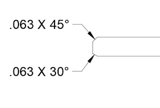
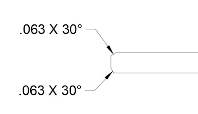
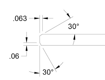
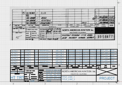
A portion of the original print used to 
create the model.
 For many years, I've created models in Fusion 360. On occasion, I've 3D printed a few of my Fusion 360 models as "desk ornaments". 

But a few weeks ago, I had a fantastic opportunity to create a model that would be used to make a part for the restoration of a B-17 Flying Fortress. 

The part was a "friction washer" for use in the throttle quadrant. And the team needed geometry that could be cut on a water jet.

It started with a reproduction of the original Boeing print. Having the original dimensions made the modeling easy. It was interesting to note that even though standards have changed in the nearly 80 years since that print was created, it's not too different from the prints I work with today. 

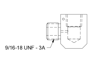
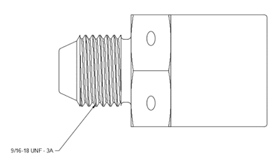
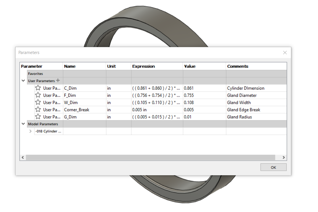
The model of the friction washer, created in 
Fusion 360

Next, was to place the view on a drawing. The first goal was to dimension the drawing as a way of verifying all the dimensions were correct. Second, the drawing is what creates the 2D DXF file for the water jet. 

Once the drawing is created, delete any information that isn't required for the waterjet. This includes borders, title blocks, dimensions, centerlines and centermarks, etc. You might even consider creating a second page in the drawing for this purpose. 

Also, make sure to save the drawing before you export. I learned the hard way when I realized that the first file I exported still had all that extra geometry. Save the file before export!

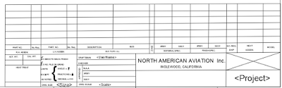
The dxf geometry sent to the waterjet

Once I recovered from my snag. I sent the files off to my colleague for cutting. 

A few days later, we had our part and it fit perfectly, making for a very satisfying little journey. 


And while this little project was well worth a victory lap, there were three minor challenges that are worth mentioning. 

1) Drawing standards have changed over the decades, and while the drawing wasn't hard to interpret, some information wasn't where I'd expect it to be. Modern 3D modelers have spoiled us. We can "slap down" a new view in seconds. For the drafters of old? Adding the simplest view would take minutes. A more complicated one? Hours. 

The number of views was kept to a minimum. A part of single thickness, such as this one, will likely have the thickness dimension called out in a note. 

2) Not only have drawing standards changed, industry standards have changed. That material specification called out in 1943? It's been long superseded by a new standard. It's even possible that the standard that superseded the 1943 standard has, in turn, been superseded itself. 

Be prepared to spend a few minutes Googling the updated standards. Thank goodness for the internet! 

3) Finally, how does one interpret the tolerances called out on the drawing? Symmetric, +/-.005 for example, is easy. Model to the nominal. But what about a tolerance such as +.010/-.000? Do you "split the difference"? Do you aim for nominal? 

In my case, I decided to aim for the dimension as it was called out on the print. I figured that was the target dimension, after all. 

And in my case. It worked! Fusion 360 gave me an excellent dxf file that the waterjet used with no issuee, and the part fit perfectly into its intended position.  

It was a wonderful opportunity to contribute to a restoration. And a wonderful learning opportunity!

Acknowledgements

Print Reproduction via my Aircorps Library Subscription

Models and drawings created in Autodesk Fusion 360

Tuesday, June 07, 2022

My Tool Won't Fit! A Design Lesson From Life.

A typical aircraft brake disk.
There's not much room for a socket!
Hands on experience is often the greatest teacher. 

And, while helping work on a friend's change tires on a light aircraft. 

In looking at the brake disk, bolted to the tire rim, I saw that there was no way one could get a socket, the ideal tool for the job, onto the bolt. 

Fortunately, my friend, having run into this case many times before, had a wrench he'd cut to fit inside the disk. So in the end, it was job that was still very easily accomplished. 

But there lies a lesson for those of who sit behind a desk and design the machines we use every day. 

Just because the fastener fits, doesn't mean the tool will! So when designing, think of ease of maintenance. 

The maintainers, who are sometimes your customers, will thank you for it! 

About the Author:

Jonathan Landeros is a degreed Mechanical Engineer and certified Aircraft Maintenance Techncian. He designs in Autodesk Inventor at work, and Autodesk Fusion 360 for home projects. 

For fun he cycles, snowboards, and turns wrenches on aircraft. 

Friday, June 03, 2022

All PLA Prints the Same, Right? WRONG!

I print a lot of Polylactic Acid (PLA) in the 3D printer at work. I've found it's a great material to work with. It prints easy, and generally gives great results. 

A sample of a different PLA print. 
Usually a great material to work with.
Sorry, the actual print is proprietary.
Almost without exception, I have great results.

At least until all of a sudden I start having problems with it! 

When printing new color, silver from Amazon the PLA started peeling off the bed. 

It didn't matter how much glue I put down on the bed, It would peel up after a few layers. 

So what to do? 

My first step was to try a few troubleshooting steps. 

First, I raised the temperature of the bed from 50 degrees Celsius to 55 degrees Celsius. No luck there. 

Next, a thorough cleaning of the bed with isopropyl alcohol. I definitely had a cleaner bed, but still, the problem persisted.

Finally, I found a trick that solved the problem. Move the nozzle .05mm closer to the bed. Success!

The Z setting adjustment in my slicer.
I moved the nozzle slightly closer to the bed.

What is it about the silver filament? I'm not sure. But during my troubleshooting, I did notice that the gray filament did appear to be laying down a thinner layer. 

My only guess is something with the dye used to color the filament. But that's just a wild guess. 

So what's the takeaway? 

Keep an eye on those layers, and remember that not all filament of the same material prints the same! 

Resources used for this post: 

3D Printer: Fusion3 F400
Slicer Software: Simplify3D

About the Author:

Jonathan Landeros is a degreed Mechanical Engineer and certified Aircraft Maintenance Techncian. He designs in Autodesk Inventor at work, and Autodesk Fusion 360 for home projects. 

For fun he cycles, snowboards, and turns wrenches on aircraft. 


Tuesday, May 10, 2022

So Solidworks Happened at Work Today - A Musing

I've spent just over 20 years working with 3D CAD programs. That experience has been nearly exclusively with the Autodesk manufacturing product line, starting with Mechanical Desktop (shortly after the earth cooled), and followed by Autodesk Inventor. 

We've all seen the ubiquitous, 3D model, floating in space.

A couple of years ago, my company decided to experiment with switching to Siemens NX.

That experiment, unfortunately, failed. Siemens NX, while a good program, wasn't the right program for the needs of my employer. 

A few months ago, my company announced that we would be going to Solidworks. 

Other than dabbling in it a few times, I've never touched Solidworks. This could be an enormous change for me. 

Or not, perhaps? 

CAD Tools - Is it just
a Virtual Toolbox?

I completed an abridged "transfer training", where we were shown where all the buttons were and how Solidworks ticks. After that, we were released upon the world. 

And what did I find? Were my eyes opened to a brand new world? Was Solidworks so much better that I wondered what I was missing? 

Did I wail and gnash my teeth because Inventor was far better and I was being forced to use this inferior product?

No. I left that training and thought, "Wow! They're really similar." 

Sure, Solidworks has an Extrude and and Extrude Cut button, while Inventor has the same options combined within one Extrude command. But they both add and remove material in the end. 

There's functions where I think Inventor has it down better, and others where I have to give it to Solidworks. 

In the end, I see it as an opportunity to learn a new skill, enrichen myself, and be more marketable in a competitive world. I think that's going to take me further in the long run. 

So I suppose the point of my writing this is to muse about how CAD programs are tools. They're not the endgame, there the means to create our designs, drawings, and help us build our products. 

And there's nothing wrong with learning a new set of tools. It can only make me a more marketable designer. 

One Final Note

If you're using Fusion 360, you can change your Pan, Zoom, Orbit shortcuts to reflect Inventor or Solidworks, among other programs? 

I've switched mine to Solidworks, it may not be the same as having Solidworks at home, but it does makes it easier when I switch from one to the other at work! 

The Pan, Zoom, and Orbit options in Fusion 360


Saturday, March 12, 2022

The Chamfer Note. Does It Say What You Mean?

Many CAD tools contain a chamfer note that I would describe as a leader style. 

You've probably seen it, probably used it even. 

It utilizes a leader to point at the chamfer, and contains both the chamfer distance, and angle in one simple note.

The advantage of this style is it's compact, easy to read, and especially easy to place when the chamfer is packed into a crowd with other nearby dimensions. 

But this dimensioning style as a subtle disadvantage. This style of dimension doesn't identify the direction of the chamfer. So if the chamfer angle is something other than 45 degrees, the angle direction is open to interpretation. 

Even though the chamfers are different, the callout is is the same. 
It's also correct in both cases.

That literally means that a chamfer in either dimension meets the print. That can cause confusion, and possibly "heated debates" when a parts acceptance or rejection hangs in the balance. 

The other option is to call out the chamfer distance and angle as separate, distinct dimensions.  This identifies the direction of the chamfer much more clearly.  


Of course everything is a trade off, and this method does take a little more room on the page than the leader style. Even on the image above, you can see that the page is a bit more cluttered, and someitmes a detail view is required to ensure all dimensions can be clearly seen. 

In the end, I find I use both. The leader style is used for 45 degree chamfers, since there isn't really an angle direction to speak of. However, when the chamfer is an angle other than 45 degrees, it's time to employ the explicit style, and make sure the direction is clearly shown. 

Ultimately, it's up to you which chamfer style you use. Perhaps you have the advantage of tribal knowledge to correctly identify these features. Or you have other means to make sure the chamfer is cut the correct way. 

If anything, this is a good practice hailing from the time when "back to the drawing board" was a much more literal statement! 

About the Author:

Jonathan Landeros is a degreed Mechanical Engineer and certified Aircraft Maintenance Techncian. He designs in Autodesk Inventor at work, and Autodesk Fusion 360 for home projects. 

For fun he cycles, snowboards, and turns wrenches on aircraft. 


Thursday, February 03, 2022

New in Fusion 360 - Improved Thread Notes

 Sometimes it's the little things that make a guy happy. 

A thread note placed
on an external thread

In this case, it's the improved thread annotation tool in the January/February Fusion 360 update. 

In short, Fusion 360 can now create an annotation for a thread note placed with the thread tool, not just the hole tool as was the case in previous updates 

That opens up the field to place thread notes onto external features. It's a capability I've personally been hoping would get added for some time. 

Admittedly, applications like Inventor have been doing this for what seems like eons, so it's hardly a "ground-breaking" feature. 

But it sure is a nice feature to have! 

All you have to do is place the note using the "Hole and Thread Note" command, and you're off and annotating. 

Locating the "Hole and Thread Note" tool

One little cool thing I noticed in my evening of poking about. 

The tool works with threads created using the "modeled' setting too! 

A modeled thread with a thread note.

I've been waiting for this enhancement for a while! I'm glad it's finally here! 


About the Author:

Jonathan Landeros is a degreed Mechanical Engineer and certified Aircraft Maintenance Techncian. He designs in Autodesk Inventor at work, and Autodesk Fusion 360 for home projects. 

For fun he cycles, snowboards, and turns wrenches on aircraft. 


Saturday, January 08, 2022

A Milestone Creating a Fusion 360 Title Block!

I have completed the task I challenged myself with in my previous post. I finished up my reproduction of a 1940s era North American Aviation title block in Autodesk Fusion 360!


The original, and Fusion 360 Title block together


It was a little tedious at times, it's a lot of repetitive sketching geometry and inserting text and properties. 

But it's completed, and ready for use. I'm sure I'll find a few more things to adjust as I test it out. 

Ultimately, I was able to recreate nearly every feature of the title block. It's not an exact match. I couldn't find a solid fill to block out the box above the part number for example. But it is close, and it will serve it's purpose just fine. 

As more features get added to Fusion 360, I'll update the title block accordingly. 

The North American Aviation tile block finished

So now, it's time to start creating drawings! From there, I'll learn more lessons and make more adjustments!

Credits:

Title Block Sourced from my Aircorps Library subscription.

About the Author:

Jonathan Landeros is a degreed Mechanical Engineer and certified Aircraft Maintenance Techncian. He designs in Autodesk Inventor, Siemens NX, at work, and Autodesk Fusion 360 for home projects. 

For fun he cycles, snowboards, and turns wrenches on aircraft. 


Sunday, January 02, 2022

A Trick - Creating Fusion 360 Title Blocks from an Image

 Happy 2022! Here's to hoping for a prosperous loop around the sun. 

One of my latest endeavors has been recreating 1940s aviation prints as 3D models in Fusion 360. The drawings are available via my Aircorps Library subscription, and they're a great look into how parts and assemblies were documented nearly 100 years ago. 

A piston for an actuator on a North American P-51 Mustang.
Model created in Autodesk Fusion 360

The models are the fun part for sure, but I also decided to recreate the drawings themselves too. 

The first part of recreating the drawing, is to recreate the title block of course. 

The title block image, ready for import into Fusion 360
\

It's still a work in progress, but I thought I'd spare a moment to document my progress.

It almost goes without saying, the process can be tedious. Since the original drawings are hand drawn, they have to be recreated from scratch. 

The thought of trying to "eyeball" the title block wasn't very appealing, but finally an idea dawned on me that made the process much less challenging. 

I imported an image of the title block, scaled it to a suitable size, and laid out the geometry on top of the image.

The title block in Fusion 360. The lines sketched in Fusion 360 are highlighted.

Overall, I felt pretty well. But there was one thing I did have to overcome

There's no image opacity setting like there are in other parts of Fusion 360. But I was able to see where my sketched lines were by highlighting them. I also extended the lines beyond the edges of the image. I can always trim them later. 

Finally, I'd also use the good old, "Delete, Inspect, Undo" trick by deleting the image, inspecting, and undoing the delete.

Overall, its working pretty well. I've found the process is much faster, accurate, and less frustrating than trying to scale by using the title block in a separate window. 

As I said earlier, it's a work in progress.  I'll share my final product when I'm done. Give me time, it might be a while! This is an "evening here and there" project! 

One Final Note

The team at Aircorps Library have done a spectacular job collecting, scanning, and sharing these vintage documents. Out of respect for their work, I won't be sharing any documents or models. Please, don't ask me to do so.

If you are really interested in their documentation, feel free to check out their site and investigate a subscription yourself! 

About the Author:

Jonathan Landeros is a degreed Mechanical Engineer and certified Aircraft Maintenance Techncian. He designs in Autodesk Inventor, Siemens NX, at work, and Autodesk Fusion 360 for home projects. 

For fun he cycles, snowboards, and turns wrenches on aircraft. 


Thursday, May 06, 2021

A Musing on Modeling Safety Wire - How Much Detail is Necessary?

A question that was recently posed to me was; "How would you model safety wire in an assembly?" 

Safety wire on a fuel
divider on an 
aircraft engine
At first, I thought I'd write a post trying to summarize the standard, and how I've seen it approached in my travels over the years. But no matter how I tried to "summarize" the standard, it ended up too long, and so dry it put me to sleep.  So instead, I'm going to try writing this briefly, and hopefully to the point. 

First of all, Safety (aka lock-wire) is small diameter wire of various sizes that is used to prevent fasteners from loosening and ultimately falling out. It should always pull in a direction that tightens the fastener. It's usually twisted with 6-8 twists per inch. 

Of course there are more details, but they're covered by standards. In my aviation maintenance travels, that standard is AC43.13-1b, issued by the Federal Aviation Administration  (FAA). In my engineering travels, that standard is NASM33540.  I'm sure there are other standards.

That's important. The standards tell the installer how to secure the fasteners with safety wire.

So when it comes time to show safety wire on a model or drawing, is it normal to show the twisted wire?  Is it modeled exactly as shown in the
image to the right?

Heck no! That takes a lot of time and computer resources, which gets expensive fast. And having a standard to reference, there's little to be gained other than bragging rights for the designer. 

Instead, I've seen, and used, on of two alternatives. 

The first, is to use a sweep in the model, showing where the wire should go. This takes a little modeling time and dedication, but it will show up on the model, and propagate to the drawing when its created.

Safety wire shown in the model.
I've colored it in red here to make it stand out. 


The modeled sweep representing the safety wire on the drawing.
A leader references the standards in the notes
.

The other, is to use sketch geometry when the drawing is created. It takes a bit of time to sketch in the drawing, but the results do a good job of showing the desired result.


Sketches on the drawing calling out the safety wire
Circles and lines represent the wire's twists.

Which ever method is used, a note can call out the standard to be complied with.  So the wire shown on on the drawing and model show where the wire should go, the note calls out the standard to reference.

If the installer has any doubts, the standard should be readily available for reference. I know in many cases, it's probably even legally required to be available. 

The next logical question for a reader may be, "How does this apply to me?" After all, while safe wire isn't uncommon, there are plenty of users who live long, fulfilling lives without ever touching safety wire.

If you get anything out of this post, ponder if there's anything that can be streamlined by adding more or less detail? How detailed does the model of that purchased part need to be? Are you spending extra time showing model details that are covered by a standards that can just be shown by a note with a leader? 

Perhaps take a few minutes to think it over. You might find you save hours! 

Acknowledgements

Models created by me in Autodesk Fusion 360

McMaster Carr models used:
  • Round Head Screws (wire lockable) - P/N 90350A310 
  • Flat Washer: P/N 92141A011
  • 45 degree elbow (37 degree flare to NPT): P/N 50715K637
  • 90 degree elbow (37 degree flare to NPT): P/N 50715K413
FAA Reference for Safetying: AC43.13-1b (See page 7-19)

NASM33540: This document is only available for purchase, so I've added a link to the old standard, MS33540.  It's very similar to NASM33540, as well as AC43-13-1b

Thursday, February 11, 2021

Getting Jacked - A Simple and Clever Way to Separate Parts

One thing using 3D CAD programs has taught me, programs like these can make assembling parts together a piece of cake! With just a few clicks, parts can be quickly placed into position.


3D CAD systems have many ways of assembling components


But just because a constraints allow us to easily assemble and disassemble parts, doesn't mean that it will be so easy to do on the assembly line, or during maintenance. 


One example is a seal, such as a gasket or packing that locks the two mating parts together. For example, in the image below, the O-ring creating the seal may cause enough friction to prevent the flanges from being easily separated. 


The O-ring sealing the components could be enough to "friction lock"
the assembly, making it difficult to take apart.


One option would be taking a screwdriver or another prying device between the flanges and pry like you're opening a casket of pirate treasure.  But while a tempting option, wedging a prybar between the flanges could result in damage to the flanges.  If the flanges are made of a soft material, such as aluminum, the odds of damaging the parts goes up significantly. 


But the designers of old did come up with a more elegant way of separating these... sticky problems. 


Many times, assemblies such as these will have tapped holes that appear to go nowhere.  They don't have a corresponding hole in any mating part.  They just appear to.... be there.

Why were these holes put there? They do have a purpose!


That's because they aren't there for the purpose of assembling parts.  They're for disassembling parts. 


They're called "jacking holes". By carefully threading screws into these holes, the two flanges can be pushed apart evenly without damaging the parts making up the assembly. 


Using a socket head cap screw to separate the flanges.


It's a simple, and elegant way of solving a challenge. 


So if you should find yourself having to disassemble an assembly similar to what I've shown here, look for those jacking holes and see if it can make your life easier. 


And if you find yourself designing a component that may present a challenge, perhaps adding a couple of jacking holes might make for a design that's easier to disassemble when the need arises! 


Opposing jacking screws help separate the flanges evenly!


About the Author:

Jonathan Landeros is a degreed Mechanical Engineer and certified Aircraft Maintenance Techncian. He designs in Autodesk Inventor, Siemens NX, at work, and Autodesk Fusion 360 for home projects. 

For fun he cycles, snowboards, and turns wrenches on aircraft. 


Standard Parts Used on this Project

A569-343 Viton O-ring - McMaster Carr Part Number 9464K173


Buna-N -343 Backup  Ring - McMaster Carr Part Number 5288T372


1/2-13 x .500 Long Socket Head Cap Screw - McMaster Carr Part Number 92185A712

Sunday, September 13, 2020

Double Checking Your Work and Subverting Mr. Murphy

I once saw a graph that showed the cost of making a change in the CAD model vs  further down in the product design cycle


Spoiler alert! It gets more expensive as you move from design, to prototype, to production.  

One need only to cases like the Takata airbag recall, or Boeing 737 Max grounding or the impact of the impact of a a production level design change in in money, company reputation, and tragically, in lives lost. 

But I'm not here to write about such heavy topics. The example I'm choosing to document is a much lower stakes version of the same thing.  It's just a basic hobbyist example that at worst, is inconvenient and marginally embarrassing.

It's an access panel based on something you'd find on an aircraft. It's a concept for a potential future hobby project. I built one back when I was in school.

So I happily modeled away in Fusion 360, creating sheet metal parts and placing fasteners from McMaster Carr

After spending a couple of evenings of casual modeling, I was done! I took that moment we all love, I leaned back, looked at my work proudly, then prepared one last check before I took my little victory lap.

The completed inspection hangar, or so I thought...

And that's when I saw it. 

The countersunk rivets I had installed were the wrong ones. I'm not sure how I missed it initially, but obviously I did. 

So first, what's wrong with the rivet? 

It's a rivet with a 78 degree countersink, which means the countersink extends to the second sheet of metal being riveted.  This is a big no-no. When the countersink extends into the second piece of metal, the larger hole required in the first sheet of metal makes for a weaker joint.

The wrong rivet. I did match the countersink angle to match the rivet for clarification.


The incorrect rivet for this application. The countersink angle is too steep


The correct rivet is a 100 degree rivet. The shallower angle prevents the head from punching into the second sheet of metal. That means a stronger, and safer joint.

The 100 degree rivet, the correct one for this application. 
I know in the model the rivet does appear to just clip the second sheet.
But past experience has taught me that this combination does work.

The shallower angle of the 100 degre countersink makes a stronger joint

So that's the technical aspect of it, what's the other lesson?

I suppose the first lesson is make sure to check the hardware before you put it in. But we all make mistakes. That's where double checking comes in. 

A final check can help prevent the last little "oops" from slipping through. Even though we can't eliminate them all, we can reduce them with a little time. 

For those of us working in industry, a second set of eyes never hurts. In some places, multiple checks on a drawing are required. It's not a bad practice at all, one I think should be taken advantage of whenever possible. 

Some may argue it takes time, but it takes much less time than undoing a costly mistake. 

I've worked in maintenance shops where "second eyes" is a standard policy on items such as fuel system repairs. In other words, the person performing the work checks his work, and then a second technician or inspector checks it again. There often are even signatures required to prove that this step was performed. 

But that's it for today's anecdote. I re-learned a few lessons in a safe environment where the only bruise was to my pride. 

I hope you can take a few lessons from this musing, and keep making cool stuff! 

About the Author:

Jonathan Landeros is a degreed Mechanical Engineer and certified Aircraft Maintenance Techncian. He designs in Autodesk Inventor, Siemens NX, at work, and Autodesk Fusion 360 for home projects. 

For fun he cycles, snowboards, and turns wrenches on aircraft. 


Additional Resources: 

A nice  rundown on different types of rivets by- Hanson Rivet and Supply

A wealth of knowledge on general airframe repairs (start at page 4-31 for the Riveting Section) -Aviation Maintenance Technician Handbook 

Standard Parts Used on this Project.

.125 Diameter, 78 Degree Solid Rivet (The Wrong One) - McMaster Carr Part Number 97483A075

.125 Diameter, 100 Degree Solid Rivet (The Right One) - McMaster Carr Part Number 96685A170

10-32 Floating Nut Plate - McMaster Carr Part Number 90857A129

.094 Diameter Rivet (to Fasten Nut Plate) - McMaster Carr Part Number 96685A143

#10 Flat Washer - McMaster Carr Part Number 92141A011

10-32 Pan Head Phillips Screw - McMaster Carr Part Number 91772A826


Friday, July 31, 2020

Designing for O-Rings and Reusing Design Features in Fusion 360

O-ring seals are hard to avoid as a mechanical designer of any type. They can be found just about anywhere that fluid, gases, or debris needs to be kept in or out of something.

An O-Ring on the end of a flashlight

As simple as they appear, there's enormous amounts of research invested in that simple, pliable polymer ring.

How does this affect the designer? Typically by the pages and pages (real or virtual), containing tables and tables of o-ring groove dimensions.
O-Rings from a
different flashlight.


When it comes time to apply that to a 3D modeler, that means creating the o-ring grooves, including some tight tolerances. The process can be extremely tedious, especially when there are multiple o-rings of different sizes involved.

So how can a user create these o-ring glands as painlessly as possible? Sure, many of us have placed the same feature so many times we have the dimensions memorized. But why do that, unless you like that sort of pain? 

While I can't speak for every CAD tool, many tools have wizards that will help create o-ring glands, as well as other common design features. Autodesk Inventor has iFeatures, Solidworks has Library Features.

Fusion 360 doesn't have a library feature as such, at least that I've found at this point. But, there is a way to create such a thing and make life a little easier.

Preparing the O-Ring Gland

The first step, is acquire the documentation with the necessary dimensions. Lately I've become partial to the Parker O-Ring Handbook myself, seeing how they know a thing or two about sealing. 

For this example, I'll use a -018 o-ring. It's a static (non moving) seal, and I'll use the male gland as an example (stop snickering, that's Parker's terminology). 

Gland Schematic from Parker O-Ring Handbook

Here are the dimensions pulled from the design tables

From Table 4-1

C=.860/.861
F = .750/.754
Corner break = .005 


From Table 4-1A 

W = .105/.110 


From Table 4-2

R = .005/.015 

O-Ring Groove Radius

Modeling the O-Ring Gland

Before creating any models in Fusion 360, enter the relevant values into the parameters dialog box. This seems like extra work, but I think it makes creating models with new sizes easier.

The Fusion 360 Parameters screen with the o-ring parameters started


Now, draw the profile of the o-ring gland, using the values from the parameters table. 

The gland profile sketched and dimensioned.

Next revolve the profile into a solid. Now, we have a solid representing the shape of the groove.

The o-ring groove revolved as a solid.

Believe or not, that's it for creating the gland. Saving it will make it available for other components to use.

Inserting the O-Ring Gland

What's needed next is a component in need of an o-ring. In this case, I've modeled a simple plug in Fusion 360.  It's similar to the threaded plugs found here on the McMaster Carr site.  I've just moved the gland location to make things a little more clear.

A threaded plug

To place the o-ring gland, right click on the file in the Data Panel and choose "Insert into Current Design".  This places the gland into the model


This inserts the gland into the plug.  Now it can be positioned by using the Move/Copy command, or assembled using the Joints command.

Placing the o-ring gland. The Move\Copy command is shown.

After positioning the gland, use the combine command to subtract the gland volume from the plug.  


Once the Combine Command has been committed, the plug is finished.  And you also have a -018 gland ready to use in your next design!

The finished plug. (Don't forget to hide the original solid!)


But undoubtedly, other o-ring sizes will be needed.  That's where using the parameters can come in handy.  Just copy the existing gland and rename it, then enter new values in the chart.


Summing it Up

I only used static o-ring grooves for this post.  There's also dynamic (moving) seals, face seals, glands that use backup rings (for higher pressures), and probably something else I'm not mentioning. I just can't get into them all, but the data is out there. It's just a matter of looking and asking questions.

As for desigining the gland, the steps I've shown here are for Fusion 360. But if you've made it this far, I hope it's the process you take away. I hope that you can find it helpful, and perhaps can apply it to what ever product you use for your design.

At the very least, I hope you walk away with resources that you can use when the time comes to design for o-rings.

And lastly, here's the list of resources I used in this post.

Parker O-Ring Handbook -  PDF Download
McMaster Carr - Website
Milwaukee Penlight - From the Home Depot Website 
Mag Instruments Maglite - Mag Instruments Website
Autodesk Fusion 360 - Autodesk Website