Find us on Google+ Inventor Tales

Tuesday, November 17, 2015

A Mid-Week PSA - A Wealth of Information from the Stainless Steel Information Center!

In my post earlier this week, I blogged about learning how the orientation of the sheet metal flat pattern in Autodesk Inventor can affect the finish of the part that comes out of a machine, and how to flip the base face to make sure that the desired side was unblemished by the laser mill bed.

In my case, the finish being applied was a #4 finish to a stainless steel sheet.  That was the nice finish that had to be protected.

Another view of a laser mill, and that finish destroying bed.
Now, this is the point where I confess something to all of you out there.

When I first heard #4 finish used in conversation, I was the guy nodding my head as if I knew of the #4 finish they spoke.

In reality, I had no idea what a #4 finish was, aside that it was special.  While I was nodding knowingly, I was tilting my head like a curious dog on the inside. I endeavored to make a few Google searches when I got back to my desk.

Admit it! We've all looked like this at one point or another! 

And Google paid off in spades.  I found the website for the Stainless Steel Information Center.

Not only did I find exactly what I needed to know about #4 finish, I found a wealth of information on stainless steel, I found definitions, information on composition, applications, corrosion properties. The list goes on and on.

I haven't even gone through the entire site yet!  But I know that I will eventually.  I'll refer to this site often!

I've already started downloading some of the handbooks for myself.

But if you're using stainless steel, thinking about using stainless steel, or you're a student wanting to learn about stainless steel, then this is a resource well worth considering.

And if you know any other great engineering materials, or anything at all, feel free to share with a comment!

And by the way!  A #4 stainless finish is what you'd find on appliances, architectural wall panels, and tank trailers, among other things.

But now you have the resources to read that yourself!

Photo Credits

Laser Mill by: By Metaveld BV [CC BY-SA 3.0 or GFDL], via Wikimedia Commons

photo credit: DSC08200.jpg via photopin (license)

Sunday, November 15, 2015

For a Good Finish - Flipping a Flat Pattern Base Face in Inventor

Laser mills can be fascinating machines to watch.  Even thought they've been around for years, watching them still feels like a little bit of science fiction.

Just watch this video from Wikipedia and try not to imagine something sci fi!


But no matter how sophisticated the tool, there are always "tricks of the trade" to get a little more out of the tool. 

One thing I've learned is the care of keeping the "good side up".  

The material in a laser mill rests on a grid of pointed steel plates I've taken to calling the "bed of nails".  

Looking at the image below, you an see pretty easily how that could mark up a surface you'd be hoping to keep free from marks.  

The laser mill bed. Certainly not the place to get a good night's sleep.
Because of that, you may have guessed it, it becomes important to keep the "good side up".  This keeps the visible side of the sheet metal off the "bed of nails", making sure it's got a clean finish. 

In Inventor, this means making sure that when clicking the flat pattern icon, the face that Inventor shows you is the "up" side.  

But how to you make sure the good side is out?

The obvious way, is to choose the "A" side right away, either by using the "A Side" tool, or by selecting that as your face when you create the flat pattern. 

But what if you need to change it after the fact?  In spite of the best efforts of the best designer, it's always possible one flat pattern is going to be reversed. 

An easy way to fix an incorrectly oriented flat pattern is just to delete it and replace it.  This might work great if a drawing using the flat pattern hasn't been created yet, but what if it has?

If a flat pattern view is created, deleting the flat pattern means recreating the view in the drawing. 

This is a fairly simple flat pattern.
But do you want to recreate it if you don't have to?


In other words?  It means more work. 

So here's an alternative that I think you might like. I'll flip the "A" side of the sample below.  I've colored one face red to make the change a little easier to follow.

Getting started with a sample part.

First, while in your sheet metal part's flat pattern, right click on the flat pattern icon and choose Edit Flat Pattern Definition.  

Accessing the flat pattern definition.

Now, a dialog box appears that allows the option to change, create, and save orientations if you'd like. In this case, it's the Flip option under the Base Face section we're interested in. 


Clicking this face flips the sheet metal face over like a pancake on the griddle.  In the flat pattern sample used here, the silver face is now visible. 

The face is flipped over

Now, switching to the drawing, the flat pattern also shows the silver side, Careful inspection will also show that the bend directions have all changed too! (Careful, the view is rotated 180 degrees).


The flipped, can completed, view.
You may noticed that the dimensions need some rearranging, but at least speaking for myself, I'd rather rearrange annotations than recreate a set of annotations.  In other words, this is a small trade off for the time saved when facing recreating entire views. 

So if you're facing flipping a sheet metal pattern over for any reason at all, I suggest considering flipping the base face.  It can be a real time saver. 

Sunday, November 08, 2015

Batch Converting Files in AutoCAD - A Very Handy Tool

Earlier this week, I was faced with saving a handful of AutoCAD files from the 2015 to a 2000 version for use in a laser mill.

Naturally, the most direct way is to open the file in AutoCAD, and save back as a 2000 version.  But there's a handful of files, so it's going to take a little bit of time to save the files one a time.

Converting files one at a time.  This is a common look for
the person stuck with that task. 
But there's a utility here to help us out with that.

It's called DWG Convert, and lets you batch convert AutoCAD files to an older version of your choosing.

To get to the tool, go to the Application Icon (the big "A" as I like to call it) and choose Save As.

On the flyout, look for the DWG Convert icon.

The DWG Convvert Icon.
Choosing this icon, you'll be greeted by the DWG Convert dialog box. And there are options to choose from.

The different areas of the DWG Convert dialog

The sections listed by the blue icons are:

1) The list of files to convert (these haven't been added yet).
2) Icons to add files to be converted.  From left to right, they are:
Add files to convert

  • Add files to convert
  • Create list of files to convert
  • Open a list of files you've previously created
  • Append files to an existing list
  • Save to list

3) This section provides a list of selection setups to choose from

4) Finally, the Conversion Setup icon allows you to modify an existing setup, or create one of your
     own.  This is the one we're going with right now.


Clicking on the Configuration Setup button shows a new dialog box.

The Conversion Setups dialog box.
Here, you can create a new setup, as well as rename, modify, or delete existing setups.

In my case, I chose to create a new setup.  Since I'm converting to 2010, I used Convert to 2000 (in place) and selected new.  This creates a new setup based on the existing one I chose.

Changing different options for the conversion.

Now modifications can be made to the setup.  These include, how the files are handled (such as a zip file, or folder of files) which format to convert to, as well as several actions to perform on the files, such as purging and error correcting.

It's listed quite nicely in the Autodesk Help System here, so I won't try to recreate that particular wheel in this post.

Accepting the settings, I'll return to the previous dialog box, and add the files I want to convert.

Adding files to convert.

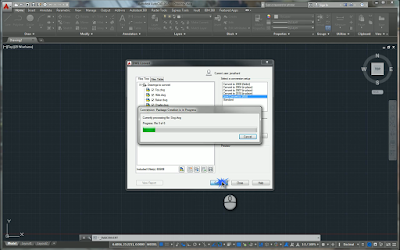
Once the files are added to the list, all that's left to do is click Convert, and let DWG Convert do its thing.

The conversion in progress.  The list can be seen in the background.
After a short span of time, depending on size, and how many files you're converting, it will all be done.

All done!
You can now get the files from the location you saved them to, and they're ready to do what you need!

So when you need to batch convert a bunch of files, here's a tool to keep in mind!

Photo Credits:

photo credit: 2 a.m. Tedium via photopin (license)

Sunday, November 01, 2015

Show Sick Constraints in Autodesk Inventor - A Newer Trick That's Worth It!

To borrow a phrase from Fiddler on the Roof, "Our old ways were once new, weren't they?"

And I'm reacquainting myself with building, changing, and modifying assemblies in my new capacity.  That means changing geometry after parts have been assembled.

And that means dealing with sick constraints!

They say an ounce of prevention is worth a pound of cure.
But sometimes you need a heaping pile of cure.
I had to change a hole into a slot in order to give a part a easier to adjust.

Note! For this post, the top nut and washer have their visibility turned off to make the slot easier to see.  But it is there!

One of these holes has to become a slot
Creating the slot is easy enough.
However there were threaded rods and nuts that were constrained to the now removed holes, and naturally, those constraints lost association.

Locating these in the browser is usually easy enough.

The sick constraints in the browser.


But then I remembered that there's a tool that will make glyphs visible on screen to show me where my problem constraints were.

It's called Show Sick Constraints, and it was actually introduced in Inventor 2014.

Clicking this tool shows glyphs for the sick constraints right in the modeling window.  By right clicking on these, the options to change the constraints become available

The glyphs shown.  Note one washer/nut combination is invisible
Choosing the Edit option, the lost constraint becomes visible.  It's represented by the red arrow.

Right click on Edit


By clicking it, I can re-associate the missing constraint to the new geometry represented by the slot. It's just like when the constraint was added in the first place.

Replacing the constraint.  The nut and washer are invisible.
This makes it easier to select the desired geometry.

When compared to fixing constraints by the "right click in the browser" method, I found this to go by quickly.  I wasn't checking the browser, and using tools like "Isolate Components and "Find in Browser" nearly as often.  And while those are great tools, "Showing Sick" made the process smoother with a minimal amount of "mouse mileage".


The constraints restored!  The glyphs can now be hidden if desired with
the "Hide All" tool net to "Show Sick"
It's a nice tool that helped me quite a bit in this particular situation, I'd suggest you take a look and add it to your repertoire of tools!

Photo Credits

photo credit: photo credit: Conefluence! via photopin (license)